Transcription
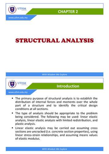
CHAPTER 2www.uthm.edu.mySTRUCTURAL ANALYSISWith Wisdom We ExploreIntroductionwww.uthm.edu.my§ The primary purpose of structural analysis is to establish thedistribution of internal forces and moments over the wholepart of a structure and to identify the critical designconditions at all sections.§ The type of analysis should be appropriate to the problembeing considered. The following may be used: linear elasticanalysis, linear elastic analysis with limited redistribution, andplastic analysis.§ Linear elastic analysis may be carried out assuming crosssections are uncracked (i.e. concrete section properties), usinglinear stress-strain relationships, and assuming means valuesof elastic modulus.With Wisdom We Explore
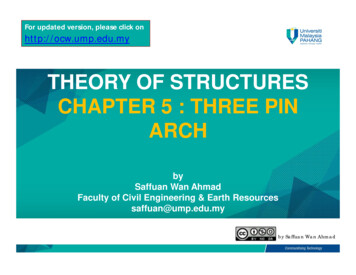
Analysis of Actionswww.uthm.edu.my§ Actions that applied on a beam may consist of beams selfweight, permanent and variable actions from slabs, actionsfrom secondary beams and other structural or non-structuralmembers supported by the beam.§ The distribution of slab actions on beams depends on the slabdimension, supporting system and boundary condition.§ Beam supporting slabs designed as spanning one-way can beconsidered to be uniformly load as shown in figure below.With Wisdom We ExploreAnalysis of Actionswww.uthm.edu.myWith Wisdom We Explore
Analysis of Actionswww.uthm.edu.mylxw 0.5.n.lx kN/mBAlyBeam AC and BDlyw 0 kN/mlxDCBeam AB and CDWith Wisdom We ExploreAnalysis of Actionswww.uthm.edu.my§ For beam supporting a two-way slab panel freely supported alongfour edge.2æ lx ö ùnl x é ú kN / mê3 - çw çl ú6 êyèø ûëlxABlylyBeam AC and BDw nl xkN / m3lxCDBeam AB and CDWith Wisdom We Explore
Analysis of Actionswww.uthm.edu.my§ There are alternatives methods which consider various supportconditions and slab continuity. The methods are, (i). Slab shearcoefficient from Table 3.15 BS 8110, (ii). Yield line analysis and (iii).Table 63 Reinforced Concrete Designer’s Handbook by Reynold.With Wisdom We ExploreAnalysis of Actionswww.uthm.edu.myw βvx.n.lx kN/mBAlyBeam AClyw βvy.n.lx kN/mlxClxDWith Wisdom We ExploreBeam CD
Example 2.1www.uthm.edu.my2FS1 (150 thk.)200 x 500200 x 500FS2 (150 thk.)FS3 (150 thk.)200 x 500200 x 500A2500200 x 500200 x 5004500Weight of concrete 25 kN/m3Finishes, ceiling 2.0 kN/m2and servicesVariable action 3.0 kN/m2(All slab)B4000200 x 500200 x 5003000200 x 5001Determine the characteristic permanent andvariable action act on beam B/1-3.3CWith Wisdom We ExploreSolution of Example 2.1www.uthm.edu.myAction on slabSelfweight 0.15 x 25Finishes, ceiling and servicesChac. Permanent action, GkChac. Variable action, Qk 3.75 kN/m2 2.0 kN/m2 5.75 kN/m2 3.0 kN/m2Distribution of actions from slabs are as follows;FS1 : ly/lx 7.5 / 2.5 3 2.0, One-way slabFS2 : ly/lx 4.0 / 3.0 1.33 2.0, Two-way slabFS3 : ly/lx 4.5 / 4.0 1.13 2.0, Two-way slabWith Wisdom We Explore
Solution of Example 2.1www.uthm.edu.my123000345002500Aw1 0.5.n.lxw2 βvy.n.lxw3 βvx.n.lx4000BCWith Wisdom We ExploreSolution of Example 2.1www.uthm.edu.myAction from slabw1 Gk 0.5 x 5.75 x 2.5 7.19 kN/mw1 Qk 0.5 x 3.00 x 2.5 3.75 kN/mFrom Table 3.15: BS 8110: Part 1: 1997w2 Gk 0.4 x 5.75 x 3.0 6.90 kN/mw2 Qk 0.4 x 3.00 x 3.0 3.60 kN/mw3 Gk 0.44 x 5.75 x 4.0 10.12 kN/mw3 Qk 0.44 x 3.00 x 4.0 5.28 kN/mWith Wisdom We Explore
Solution of Example 2.1www.uthm.edu.myActions on beamBeam selfweight 0.20 x (0.5 – 0.15) x 25 1.75 kN/mSpan 1-2Permanent action,GkVariable action, Qk 7.19 6.90 1.75 15.84 kN/m 3.75 3.60 7.35 kN/mSpan 2-3Permanent action, GkVariable action, Qk 7.19 10.12 1.75 19.06 kN/m 3.75 5.28 9.03 kN/mGk 15.84 kN/mQk 7.35 kN/m3000Gk 19.06 kN/mQk 9.03 kN/m4500With Wisdom We ExploreCombination of Actionswww.uthm.edu.my§ “Combination of action” is specifically used for the definition of themagnitude of actions to be used when a limit state is under theinfluence of different actions.§ For continuous beam, “Load cases” is concerned with thearrangement of the variable actions to give the most unfavourableconditions.§ If there is only one variable actions (e.g. Imposed load) in acombination, the magnitude of the actions can be obtained bymultiplying them by the appropriate factors.§ If there is more than one variable actions in combination, it isnecessary to identify the leading action(Qk,1) and otheraccompanying actions (Qk,i). The accompanying actions is alwaystaken as the combination value.With Wisdom We Explore
Combination of Actionswww.uthm.edu.my§ Design values of actions, ultimate limit state-persistent andtransient design situationsWith Wisdom We ExploreLoad Cases/ and Combinationwww.uthm.edu.myClause 5.1.3 : MS EN 1992-1-1§ In considering the combinations of actions, the relevant casesshall be considered to enable the critical design conditions tobe established at all sections, within the structure or part ofthe structure considered.§ For simply supported beam, the analysis for bending andshear force can be carried out using statically determinateapproach. For the ultimate limit state we need only considerthe maximum load of 1.35Gk 1.5Qk on the span.§ While for continuous beam a simplification in the number ofload arrangements for use in a Country is required, referenceis made to its National Annex. The following simplified loadarrangements are recommended for buildings:With Wisdom We Explore
Load Cases and Combinationwww.uthm.edu.mySection 5.1.3 : MS EN 1992-1-1Load set 1: Alternate or adjacent spans loaded (ContinuousBeam)§ Alternate span carrying the design permanent and variableload (1.35Gk 1.5Qk), other spans carrying only the designpermanent loads (1.35Gk)§ Any two adjacent spans carrying the design permanent andvariable loads (1.35Gk 1.5Qk), all other spans carrying onlythe design permanent load (1.35Gk)With Wisdom We ExploreLoad Cases and Combinationwww.uthm.edu.myAlternate spans loaded1.35Gk 1.5Qk1.35Gk 1.5Qk1.35Gk1.35Gk1.35Gk 1.5Qk1.35Gk1.35Gk 1.5Qk1.35GkWith Wisdom We Explore
Load Cases and Combinationwww.uthm.edu.myAdjacent Span Loaded1.35Gk 1.5Qk1.35Gk 1.5Qk1.35Gk 1.5Qk1.35Gk1.35Gk 1.5Qk1.35Gk1.35Gk1.35Gk1.35Gk1.35Gk1.35Gk 1.5Qk1.35Gk 1.5QkWith Wisdom We ExploreLoad Cases and Combinationwww.uthm.edu.myUK National Annex & Malaysia National AnnexLoad set 2: All or alternate spans loaded (Continuous Beam)§ All span carrying the design permanent and variable loads(1.35Gk 1.5Qk)§ Alternate span carrying the design permanent and variableload (1.35Gk 1.5Qk), other spans carrying only the designpermanent loads (1.35Gk)With Wisdom We Explore
Load Cases and Combinationwww.uthm.edu.my§ All span loaded1.35Gk 1.5Qk1.35Gk 1.5Qk1.35Gk 1.5Qk1.35Gk 1.5Qk§ Alternate span loaded1.35Gk 1.5Qk1.35Gk 1.5Qk1.35Gk1.35Gk1.35Gk 1.5Qk1.35Gk1.35Gk 1.5Qk1.35GkWith Wisdom We ExploreLoad Cases and Combinationwww.uthm.edu.my§ The shear force and bending moment diagrams can be drawnfor each of the load cases required in the patterns of loading.§ A composite diagram comprising a profile indicating themaximum values including all possible load cases can bedrawn; this is known as an envelope.With Wisdom We Explore
Load Cases and Combinationwww.uthm.edu.myLoad Case 1Load Case 2SFDSFDBMDBMDWith Wisdom We ExploreLoad Cases and Combinationwww.uthm.edu.myLoad Case 3SHEAR FORCE DIAGRAM ENVELOPEBENDING MOMENT DIAGRAM ENVELOPESFDBMDWith Wisdom We Explore
Method of Structural Analysiswww.uthm.edu.my§ Three analysis methods may be used in order to obtain shearforce and bending moment for design purposes. There are;Elastic analysis using moment distribution method(Modified Stiffness Method)Simplified method using shear and moment coefficientfrom Table 3.6: BS 8110: Part 1.Using commercial analysis software such as Staad Pro,Esteem, Ansys, Lusas, etc.With Wisdom We ExploreMoment Distribution Methodwww.uthm.edu.my§ Moment distribution method is only involving distributionmoments to joint repetitively.§ The accuracy of moment distribution method is dependent tothe number repeat which does and usually more than 5repeat real enough. Right value will be acquired when nomore moments that need distributed.§ In general the value is dependent to several factor as : Fixed end moment Carry over factor Member Stiffness Factor (distribution factor)With Wisdom We Explore
Moment Distribution Methodwww.uthm.edu.myFixed end moment (FEM)§ The moment at the fixed joints of a loaded member are calledfixed-end moment.§ This moment can be determined from table below, dependingupon the type of loading on the member.Carry over factor (CO)§ The carry-over factor to a fixed end is always 0.5, otherwise itis 0.0.With Wisdom We ExploreMoment Distribution Methodwww.uthm.edu.myFixed End MomentWith Wisdom We Explore
Moment Distribution Methodwww.uthm.edu.myWith Wisdom We ExploreMoment Distribution Methodwww.uthm.edu.myWith Wisdom We Explore
Moment Distribution Methodwww.uthm.edu.myWith Wisdom We ExploreMoment Distribution Methodwww.uthm.edu.myWith Wisdom We Explore
Example 2.2www.uthm.edu.myA series of 250 x 400 mm reinforced concrete beams spaced at 3 mcentres and spanning 7.5 m support a 175 mm thick reinforced concreteslab as shown in Figure 2.1. If the variable floor action is 3 kN/m2 and theload induced by the weight of concrete is 25 kN/m3, calculate themaximum shear force and bending moment of beam B/1-2.With Wisdom We ExploreSolution of Example 2.2www.uthm.edu.mySlabPermanent action, gk from 175 mm slab: 25 x 0.175 4.38 kN/m2Variable action, qk : 3.0 kN/m2Total ultimate load : 1.35 (4.38) 1.5(3.0) 10.41 kN/m2BeamUltimate load from slab : 10.41 x (1.5x2) 31.23 kN/mBeam self-weight, Gk : 25 x 0.4 x 0.25 2.5 kN/mUltimate load for beam : 1.35 x 2.5 3.38 kN/mTotal ultimate load, w: 31.23 3.38 34.61 kN/mMaximum shear force wL/2 34.61 x 7.5/2 129.79 kNMaximum bending moment wL2/8 34.61 x 7.52/8 243.35 kNmWith Wisdom We Explore
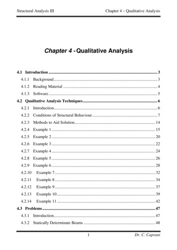
Example 2.3www.uthm.edu.myFigure below shows the first floor layout plan of commercialbuilding. If all beams size are 300 x 500 mm, determine thefollowing;1.2.Characteristic permanent and variable action act on the beam 2/A-Eif all slab thickness are 150 mm and the brickwall heights is 3m.Shear force and bending moment envelope of beam 2/A-E.Given the following data;Variable load on slabFinishes, ceiling & servicesUnit weight of concrete 4.0 kN/m21.5 kN/m225 kN/m3With Wisdom We ExploreExample 2.3www.uthm.edu.myWith Wisdom We Explore
Solution of Example 2.3www.uthm.edu.my1) Characteristic permanent and variable action act on the beam 2/A-EAction on slabPermanent action, GkSelfweight of slabFinishes, ceiling and serviceTotal permanent action on slabVariable action, QkAction on beamPermanent action, GkLoad from slabBeam selfweightBrickwallTotal permanent action on beamVariable action, QkLoad from slab 0.15 x 25 3.75 kN/m21.5 kN/m25.25 kN/m24.0 kN/m2 0.5 x 5.25 x 3 7.88 kN/m(0.3 x (0.5 – 0.15) x 25) 2.63 kN/m2.6 x 3 7.8 kN/m18.31 kN/m 0.5 x 4.0 x 3.0 6.00 kN/mWith Wisdom We ExploreSolution of Example 2.3www.uthm.edu.my2) Shear force and bending moment envelope of beam 2/A-E.LoadingWith Wisdom We Explore
Solution of Example 2.3www.uthm.edu.myMoment of Inertia, II bh3/12 300 x 5003/12 3.125 x 109 mm4Stiffness, KA-BB-CC-DD-EKAB KBA 3I/L 3 x 3.125 x 109/8000 1.17 x 106 mm3KBC KCB 4I/L 4 x 3.125 x 109/8000 1.56 x 106 mm3KCD KDC 4I/L 4 x 3.125 x 109/8000 1.56 x 106 mm3KDE KED 3I/L 3 x 3.125 x 109/8000 1.17 x 106 mm3Distribution Factor, DFJoint A & E DFAB & DFEDJoint B DFBADFBCJoint C DFCBDFCDJoint D DFDCDFDE KAB / (KAB 0) 1.17 / (1.17 0) 1.0 KBA / (KBA KBC) 1.17 / (1.17 1.56) 0.43 KBC / (KBA KBC) 1.56 / (1.17 1.56) 0.57 KCB / (KCB KCD) 1.56 / (1.56 1.56) 0.50 KCD / (KCB KCD) 1.56 / (1.56 1.56) 0.50 KDC / (KDC KDE) 1.56 / (1.17 1.56) 0.57 KDE / (KDC KDE) 1.17 / (1.17 1.56) 0.43With Wisdom We ExploreSolution of Example 2.3www.uthm.edu.myLoad Case 1Fix End Moment, FEM-M- AB MBA wL2/12 33.72 x 82/12 179.84 kNm- BC MCB wL2/12-M 33.72 x 82/12 179.84 kNm- CD MDC wL2/12-M 33.72 x 82/12 179.84 kNm- DE MED wL2/12-M 33.72 x 82/12 179.84 kNmWith Wisdom We Explore
Solution of Example 2.3www.uthm.edu.myWith Wisdom We ExploreSolution of Example 2.3www.uthm.edu.myLoad Case 2Fix End Moment, FEM-M- AB MBA wL2/12 33.72 x 82/12 179.84 kNm- BC MCB wL2/12-M 24.72 x 82/12 131.84 kNm- CD MDC wL2/12-M 33.72 x 82/12 179.84 kNm- DE MED wL2/12-M 24.72 x 82/12 131.84 kNmWith Wisdom We Explore
Solution of Example 2.3www.uthm.edu.myWith Wisdom We ExploreSolution of Example 2.3www.uthm.edu.myLoad Case 3Fix End Moment, FEM-M- AB MBA wL2/12 24.72 x 82/12 131.84 kNm- BC MCB wL2/12-M 33.72 x 82/12 179.84 kNm- CD MDC wL2/12-M 24.72 x 82/12 131.84 kNm- DE MED wL2/12-M 33.72 x 82/12 179.84 kNmWith Wisdom We Explore
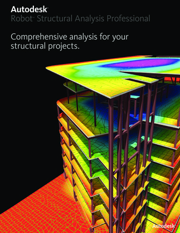
Solution of Example 2.3www.uthm.edu.myWith Wisdom We ExploreSolution of Example 2.3www.uthm.edu.mySFD EnvelopeBMD EnvelopeWith Wisdom We Explore
Simplified Methodwww.uthm.edu.my§ The analysis using moment distribution method is timeconsuming and is more conveniently carried out usingstandard computer technique.§ Therefore, as a simplification BS 8110 cl. 3.4.3 can be use.Table 3.5 are given in BS 8110 which enable a conservativeestimate of shear force and bending moment values to bedetermined for the design of continuous beam.§ There are conditions which must be satisfied in each casebefore these tables can be used. They are:With Wisdom We ExploreSimplified Methodwww.uthm.edu.my The beams should be approximately equal span. The characteristic variable action Qk may not exceed the characteristicpermanent action Gk. Load should be substantially uniformly distributed over three or morespans. Variation in span length should not exceed 15% of the longest span.(1.35Gk 1.5Qk)With Wisdom We Explore
Simplified Methodwww.uthm.edu.myEnd SpanBendingMomentsInterior s0.55F0.45F0.55F0.60FWith Wisdom We ExploreExample 2.4www.uthm.edu.myBy using simplified method, analyze the beams shown below.F 1.35Gk 1.5Qk 1.35(18.31) 1.5(6.00) 33.72 kN/m x 8 m 269.75 kNWith Wisdom We Explore
Solution of Example 2.4www.uthm.edu.myShear force and bending moment diagrams0.45F 121.39 kN0.55F 148.36 kN0.60F 161.85 kN0.11FL 237.38 kNm0.09FL 194.22 kNm0.60F 161.85 kN0.55F 148.36 kN0.55F 148.36 kN0.08FL 172.64kNm0.07FL 151.06 kNm0.55F 148.36 kN0.45F 121.39 kN0.11FL 237.38 kNm0.07FL 151.06 kNm0.09FL 194.22 kNmWith Wisdom We ExploreMoment Redistributionwww.uthm.edu.my§ Plastic behavior of RC at the ULS affects the distribution of momentin structure.§ To allow for this, the moment derived from an elastic analysis maybe redistributed based on the assumption that plastic hinges haveformed at the sections with the largest moment.§ From design point of view, some of elastic moment at support canbe reduced, but this will increasing others to maintain the staticequilibrium of the structure.§ The purpose or moment redistribution is to reduced the bendingmoment at congested zone especially at beam-column connectionof continuous beam support. Therefore, the amount ofreinforcement at congested zone also can be reduced then it willresult the design and detailing process become much easier.With Wisdom We Explore
Moment Redistributionwww.uthm.edu.my§ EC2: Section 5.5 permit the moment redistribution with thefollowing requirement;§ The resulting distribution remains in equilibrium with the load.§ The continuous beam are predominantly subject to flexural.§ The ratio of adjacent span should be in the range of 0.5 to 2§ There are other restrictions on the amount of momentredistribution in order to ensure ductility of the beam such as gradeof reinforcing steel and area of tensile reinforcement and hence thedepth of neutral axis.§ Class A reinforcement; redistribution should 20%§ Class B and C reinforcement; redistribution should 30%With Wisdom We ExploreExample 2.5www.uthm.edu.myBased on results obtained from Example 2.3, redistribute 20% ofmoment at support.Solution:Original moment at support B & DReduced moment (20%) 231.21 kNm 0.8 x 231.21 184.97 kNmOriginal moment at support CReduced moment (20%) 154.14 kNm 0.8 x 154.14 123.31 kNmWith Wisdom We Explore
Solution of Example 2.5www.uthm.edu.my184.97 kNmLoad Case 133.72 kN/mSpan A - BΣMB 0VA(8) – 33.72(8)2/2 184.97 0VA 894.07 / 8 111.76 kN8mVAΣFy 0111.76 VB1 – 33.72(8) 0VB1 158.0 kNVB1184.97 kNmSpan B - C123.21 kNm33.72 kN/mΣMC 0VB2(8) – 33.72(8)2/2 123.21 - 184.97 0VB2 1140.8 / 8 142.60 kN8mVB2VC1ΣFy 0142.60 VC1 – 33.72(8) 0VC1 127.16 kNWith Wisdom We ExploreSolution of Example 2.5www.uthm.edu.my184.97 kNm123.21 kNmSpan C - D33.72 kN/mΣMD 0VC2(8) – 33.72(8)2/2 - 123.21 184.97 0VC2 1017.28 / 8 127.16 kN8mVD1VC2ΣFy 0127.16 VD1 – 33.72(8) 0VD1 142.60 kN184.97 kNmSpan D - E33.72 kN/mΣME 0VD2(8) – 33.72(8)2/2 - 184.97 0VD2 1264.01 / 8 158.0 kNΣFy 0158.0 VE – 33.72(8) 0VE 111.76 kN8mVD2With Wisdom We ExploreVE
Solution of Example 2.5www.uthm.edu.my184.97 kNmLoad Case 233.72 kN/mSpan A - BΣMB 0VA(8) – 33.72(8)2/2 184.97 0VA 894.07 / 8 111.76 kN8mVAΣFy 0111.76 VB1 – 33.72(8) 0VB1 158.0 kNVB1184.97 kNmSpan B - C123.21 kNm24.72 kN/mΣMC 0VB2(8) – 24.72(8)2/2 123.21 - 184.97 0VB2 852.8 / 8 106.60 kN8mVB2VC1ΣFy 0106.60 VC1 – 24.72(8) 0VC1 91.16 kNWith Wisdom We ExploreSolution of Example 2.5www.uthm.edu.my184.97 kNm123.21 kNmSpan C - D33.72 kN/mΣMD 0VC2(8) – 33.72(8)2/2 - 123.21 184.97 0VC2 1017.28 / 8 127.16 kN8mVD1VC2ΣFy 0127.16 VD1 – 33.72(8) 0VD1 142.60 kN184.97 kNmSpan D - E24.72 kN/mΣME 0VD2(8) – 24.72(8)2/2 - 184.97 0VD2 976.01 / 8 122.0 kNΣFy 0122.0 VE – 24.72(8) 0VE 75.76 kN8mVD2With Wisdom We ExploreVE
Solution of Example 2.5www.uthm.edu.my184.97 kNmLoad Case 324.72 kN/mSpan A - BΣMB 0VA(8) – 24.72(8)2/2 184.97 0VA 606.07 / 8 75.76 kN8mVAΣFy 075.76 VB1 – 24.72(8) 0VB1 122.0 kNVB1184.97 kNmSpan B - C123.21 kNm33.72 kN/mΣMC 0VB2(8) – 33.72(8)2/2 123.21 - 184.97 0VB2 1140.8 / 8 142.60 kN8mVB2VC1ΣFy 0142.60 VC1 – 33.72(8) 0VC1 127.16 kNWith Wisdom We ExploreSolution of Example 2.5www.uthm.edu.my184.97 kNm123.21 kNmSpan C - D24.72 kN/mΣMD 0VC2(8) – 24.72(8)2/2 - 123.21 184.97 0VC2 729.28 / 8 91.16 kN8mVD1VC2ΣFy 091.16 VD1 – 24.72(8) 0VD1 106.60 kN184.97 kNmSpan D - E33.72 kN/mΣME 0VD2(8) – 33.72(8)2/2 - 184.97 0VD2 1264.01 / 8 158.0 kNΣFy 0158.0 VE – 33.72(8) 0VE 111.76 kN8mVD2With Wisdom We ExploreVE
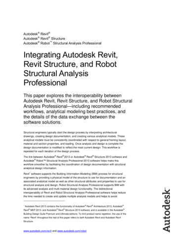
Solution of Example 2.5www.uthm.edu.mySFD EnvelopeAfter 20%RedistributionBMD EnvelopeAfter 20%RedistributionWith Wisdom We Explore
STRUCTURAL ANALYSIS With Wisdom We Explore www.uthm.edu.my CHAPTER 2 § The primary purpose of structural analysis is to establish the distribution of internal forces and moments over the whole part of a structure and to identify the critical design conditions at all sections. § The type of analysis should be appropriate to the problem .