Transcription
GENETX TMGUITARPROCESSORUSER’S GUIDE
WarningFor your protection, please read the following:Water and Moisture: Appliances should not be used near water(e.g. near a bathtub, washbowl, kitchen sink, laundry tub, in a wetbasement, or near a swimming pool, etc.) Care should be taken sothat objects do not fall and liquids are not spilled into the enclosurethrough openings.These symbols are internationally accepted symbols that warn of potentialhazards with electrical products.The lightning flash means that there aredangerous voltages present within the unit.The exclamation point indicatesthat it is necessary for the user to refer to the owners manual.These symbols warn that there are no user serviceable parts inside the unit.Do not open the unit. Do not attempt to service the unit yourself. Refer allservicing to qualified personnel. Opening the chassis for any reason will voidthe manufacturer’s warranty. Do not get the unit wet. If liquid is spilled onthe unit, shut it off immediately and take it to a dealer for service.Disconnect the unit during storms to prevent damage.U.K. Mains Plug WarningA molded mains plug that has been cut off from the cord is unsafe.Discard the mains plug at a suitable facility. Never under any circumstances should you insert a damaged or cut mains plug into a 13amp power socket. Do not use the mains plug without the fuse coverin place. Replacement fuse covers can be obtained from your local retailer. Replacement fuses are 13 amps and MUST be ASTA approved toBS1362.Grounding or Polarization: Precautions should be taken so thatthe grounding or polarization means of an appliance is not defeated.Power Cord Protection: Power supply cords should be routed sothat they are not likely to be walked on or pinched by items placedupon or against them, paying particular attention to cords at plugs,convenience receptacles, and the point where they exit from theappliance.Servicing: To reduce the risk of fire or electrical shock, the usershould not attempt to service the appliance beyond that described inthe operating instructions. All other servicing should be referred toqualified service personnel.For units equipped with externally accessible fuse receptacle: Replace fuse with same type and rating only.Safety InstructionsElectromagnetic CompatibilityNotice for customers if your unit is equipped with a power cord.Operation is subject to the following conditions: This device may not cause harmful interference. This device must accept any interference received, includinginterference that may cause undesired operation. Use only shielded interconnecting cables. Operation of this unit within significant electromagnetic fieldsshould be avoided.Warning:This appliance must be earthed.The cores in the mains lead are colored in accordance with the followingcode:Green and Yellow - Earth Blue - NeutralBrown - LiveAs colors of the cores in the mains lead of this appliance may not correspond with the colored markings identifying the terminals in your plug, proceed as follows: The core which is colored green and yellow must be connected to theterminal in the plug marked with the letter E, or with the earth symbol, or colored green, or green and yellow. The core which is colored blue must be connected to the terminalmarked N, or colored black. The core which is colored brown must be connected to the terminalmarked L, or colored red.This equipment may require the use of a different line cord, attachmentplug, or both, depending on the available power source at installation. If theattachment plug needs to be changed, refer servicing to qualified servicepersonnel who should refer to the table below.The green/yellow wire shallbe connected directly to the unit’s chassis.CONDUCTORLLIVEWIRE COLORNormalAltBROWNBLACKNNEUTRALBLUEWHITEEEARTH GNDGREEN/YELGREENWarning: If the ground plug is defeated, certain fault conditions in the unitor in the system to which it is connected can result in full line voltagebetween chassis and earth ground. Severe injury or death can then result ifthe chassis and earth ground are touched simultaneously.IPower Sources: The appliance should be connected to a powersupply only of the type described in the operating instructions or asmarked on the appliance.
DECLARATION OF CONFORMITYManufacturer’s Name:Manufacturer’s Address:DigiTech8760 S. Sandy ParkwaySandy, Utah 84070, USAdeclares that the product:Product name:GNX2Note: Product name may be suffixed by the letters EX, EU, JA, and UK.Product option:all (requires Class II power adapter that conforms to the requirements of EN60065, EN60742, or equivalent.)conforms to the following Product Specifications:Safety:IEC60065 (1998)EN 60065 (1993)EMC:EN 55013 (1990)EN 55020 (1991)Supplementary Information:The product herewith complies with the requirements of the Low Voltage Directive 72/23/EEC and the EMC Directive 89/336/EEC as amendedby Directive 93/68/EEC.DigiTech / Johnson8760 S. Sandy ParkwaySandy, Utah 84070, USADate: May 25, 2001European Contact:Your local DigiTech / Johnson Sales and Service Office orHarman Music Group8760 South Sandy ParkwaySandy, Utah84070 USAPh: (801) 566-8800Fax: (801) 568-7573WarrantyWe atDigiTech are very proud of our products and back-up each one we sell with the following warranty:1.The warranty registration card must be mailed within ten days after purchase date to validate this warranty.2. DigiTech warrants this product, when used solely within the U.S., to be free from defects in materials and workmanshipunder normal use and service.3. DigiTech liability under this warranty is limited to repairing or replacing defective materials that show evidence of defect, provided the product is returned to DigiTech WITH RETURN AUTHORIZATION, where all parts and labor will be covered up toa period of one year. A Return Authorization number may be obtained from DigiTech by telephone.The company shall not beliable for any consequential damage as a result of the product's use in any circuit or assembly.4. Proof-of-purchase is considered to be the burden of the consumer.5. DigiTech reserves the right to make changes in design, or make additions to, or improvements upon this product withoutincurring any obligation to install the same on products previously manufactured.6.The consumer forfeits the benefits of this warranty if the product's main assembly is opened and tampered with by anyoneother than a certified DigiTech technician or, if the product is used with AC voltages outside of the range suggested by themanufacturer.7.The foregoing is in lieu of all other warranties, expressed or implied, and DigiTech neither assumes nor authorizes any person to assume any obligation or liability in connection with the sale of this product. In no event shall DigiTech or its dealersbe liable for special or consequential damages or from any delay in the performance of this warranty due to causes beyondtheir control.NOTE:The information contained in this manual is subject to change at any time without notification. Some information containedin this manual may also be inaccurate due to undocumented changes in the product or operating system since this version of themanual was completed.The information contained in this version of the owner's manual supersedes all previous versions.II
IV
Table of ContentsIntroduction.Quick Start . . . . . . . . . . . . . . . . . .Making Connections . . . . . . . .Apply Power . . . . . . . . . . . . . .Select an Output Mode . . . . .Select The Target System SetupSelect a Preset . . . . . . . . . . . .A Guided Tour of the GNX2 . . . .The Front Panel . . . . . . . . . . .The Rear Panel . . . . . . . . . . . .Getting Started . . . . . . . . . . . . . . .Making Connections . . . . . . . .Mono Operation . . . . . . .Stereo Operation . . . . . . .Direct to a Mixing ConsoleS/PDIF Digital Output . . . . . . .Applying Power . . . . . . . . . . .About the GNX2 . . . . . . . . . . . . .The Presets . . . . . . . . . . . . . .Performance Mode . . . . . . . . .Preset Mode . . . . . . . . . . . . . .FX Mode . . . . . . . . . . . . . . . .The Footswitches . . . . . . . . . .The Expression Pedal . . . . . .Bypass Mode . . . . . . . . . . . . .Tuner Mode . . . . . . . . . . . . . .Jam-A-Long . . . . . . . . . . . . . . .Learn-A-Lick Mode . . . . . . . . .Rhythm Trainer . . . . . . . . . . . . . . .1. . . .2. . . .2. . . .2. . . .2. . . .2. . . .2. . . .3. . . .3. . . .6. . . .7. . . .7. . . .7. . . .7. . . .8. . . .8. . . .8. . . .9. . . .9. . . .9. . . .9. . . .9. . . .10. . . .10. . . .10. . . .10. . . .10. . . .11. . . .11.Editing/Creating a Preset . . . . . . . . . . . . . .Amp/Cabinet Modeling . . . . . . . . . . . . . . .Amp Models . . . . . . . . . . . . . . . . . . . .Cabinet Types . . . . . . . . . . . . . . . . . . .Editing Amp Models and Cabinet TypesSelecting Amp/Cabinet Models . . .Adjusting Amp Parameters . . . . . .Cabinet Tuning . . . . . . . . . . . . . . .Creating HyperModels . . . . . . . . . .Saving HyperModels (Amp Save)Editing the Effects . . . . . . . . . . . . . . . . . . .Storing/Copying a Preset . . . . . . . . . .13.13.13.13.13.13.14.14.14.15.15.15.16Effects and 22.23.23.24.24.24.25.25.Editing FunctionsEffect Definitions . . . . . . . . . . . .Wah-Pickup . . . . . . . . . . . .Compressor . . . . . . . . . . .Whammy/IPS . . . . . . . . . . .Intelligent Pitch Shifting (IPS)Detuning . . . . . . . . . . . . . .Pitch Shifter . . . . . . . . . . . .Stomp Box Modeling . . . . .EQ . . . . . . . . . . . . . . . . . . .Noise Gate . . . . . . . . . . . . .Talker . . . . . . . . . . . . . . . .Chorus/Mod Effects . . . . . .Chorus . . . . . . . . . . . . .Flange . . . . . . . . . . . . . .Phaser . . . . . . . . . . . . .Triggered Flanger . . . . .Triggered Phaser . . . . . .Tremolo . . . . . . . . . . . .Panner . . . . . . . . . . . . .Vibrato . . . . . . . . . . . . .Rotary SpeakerAutoYa . . . .YaYa . . . . . .SynthTalk . .Envelope FilterDetune . . . . . .Pitch Shift . . . .Delay . . . . . . .Reverb . . . . .25.25.26.26.26.27.27.27.28.Select a Preset . . . . . . . . . . . . . . . . . . . . . . . . . .Create a HyperModel . . . . . . . . . . . . . . . . . . .Select the Green Channel Amp and Cabinet .Select the Red Channel Amp and Cabinet . .Adjust the Green Channel Parameters . . . . .Adjust the Red Channel Parameters . . . . . . .Tune the Cabinets (optional) . . . . . . . . . . . .Warp the Green and Red Channels TogetherSave the HyperModel . . . . . . . . . . . . . . . .Select Models for the Preset’s Channels . . . .Edit the Preset . . . . . . . . . . . . . . . . . . . .Select the Pickup Type . . . . . . . . . . . . . .Turn the Compressor Off . . . . . . . . . . .Turn the Whammy /IPS Off . . . . . . . . .Turn the Stompbox Modeling Off . . . . . .Adjust the Noise Gate . . . . . . . . . . . . . .Turn the Talker Off . . . . . . . . . . . . . . .Select and Adjust the Chorus . . . . . . . .Turn the Delay Off . . . . . . . . . . . . . . . . .Select and Adjust the Reverb . . . . . . . . .Store the Preset . . . . . . . . . . . . . . . . . . 4.34.34.35.35.35Other FunctionsTutorial.Expression Pedal . . . . . . . . . . . . . . . . . . .LFOs . . . . . . . . . . . . . . . . . . . . . . . . .Amp Footswitch . . . . . . . . . . . . . . .Expression Parameter Assignment ListUtilities . . . . . . . . . . . . . . . . . . . . . . . . . .Mono/Stereo Output . . . . . . . . . . . .Target System Setup . . . . . . . . . . . . .Volume Pedal Update . . . . . . . . . . . .V-Switch Threshold . . . . . . . . . . . . . .Expression Pedal Calibration . . . . . .Bank Names . . . . . . . . . . . . . . . . . . .MIDI Channel . . . . . . . . . . . . . . . . . .Bulk Dump . . . . . . . . . . . . . . . . . . . .MIDI Preset Dump . . . . . . . . . . . . . .User Amp Dump . . . . . . . . . . . . . . .MIDI Mapping . . . . . . . . . . . . . . . . . .MIDI Merge . . . . . . . . . . . . . . . . . . .Digital Level . . . . . . . . . . . . . . . . . . .Factory Reset . . . . . . . . . . . . . . . . . .GenEdit Editor/Librarian . . . . . . . .PC . . . . . . . . . . . . . . . . . . . . . . .Mac . . . . . . . . . . . . . . . . . . . . . .Appendix . . . . . . . .Preset List . . . . . . . .MIDI CC List . . . . .MIDI ImplementationSpecifications . . . . 3.43.44.44.45.45.45.46.46.47.48.48V
IntroductionIntroductionThe DigiTech GNX2, is the most advanced guitar processor of its kind. Thanks to the highly advanced technology provided by GeNetX , and the extreme horsepower contained in the Audio DNA DSP engine,you now have the tools to literally create your own guitar amplifier and speaker cabinet models. All of thispower lets you create a sound that is your own. In addition to designing models, the GNX2 has a library fullof studio quality effects.The intuitive user interface makes programming as simple as turning a knob. However, your time would bewell spent by reading through this User’s Guide with your GNX2 in front of you.Included ItemsBefore you tear open the packaging and toss the manual over your shoulder, please check to make sure thefollowing items have been included: GNX2 PSS3 Power Supply Warranty Card User’s Guide GenEdit Editor/Librarian CDThe utmost care was taken in the manufacturing and packaging your GNX2. Everything should be includedand in perfect working condition. However, if you find anything missing, please contact the factory at once.Please take a moment to fill out the warranty card. It is your safeguard in the unlikely event that the GNX2develops a problem.1
IntroductionQuick StartThe Quick Start section is included for those of you who would rather play now and read later.Making ConnectionsConnect your instrument to the INPUT jack on the rear panel. Connect the LEFT/RIGHTOUTPUTS to the input(s) of your amplifier(s), power amp, or mixer.Apply PowerTurn the OUTPUT knob on the rear panel of the GNX2 all the way down (fully counter clockwise).Connect the plug of the PSS3 power supply to the POWER jack on the GNX2. Connect the other endof the PSS3 power supply to an AC outlet and turn the GNX2 POWER switch on. Turn youramplifier(s) on, and adjust the volume(s) to a normal playing level. Gradually increase the GNX2’sOUTPUT volume.Select an Output ModePress the UTILITY button and use the DATA WHEEL to select either the Stereo or Mono outputmode.Select The Target System SetupThe GNX2 needs to know the type of amplification system it will be used with. After selecting anOutput, press the RHYTHM button. The Target System Setup menu is displayed. Use the DATAWHEEL to select an amplification system, and press EXIT to return to Performance mode.Select a PresetThe GNX2 comes with 64 pre-programmed Factory Presets, and 64 User Presets. From the factory, theUser Presets are exact duplicates of the Factory Presets.This lets you experiment without losing any ofthe original presets.Use the BANK footswitches to select a Bank, and Footswitches 1-4 to select a preset. The DATAWHEEL can also be used to select a preset. After you find a preset you like, you can edit it. See Editingand Creating a Preset page 13.2
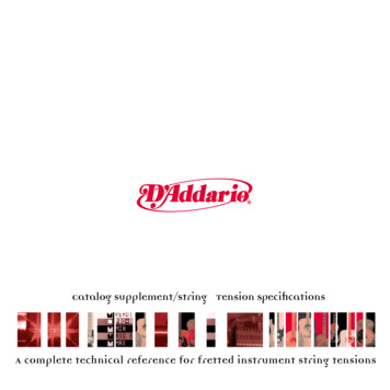
IntroductionA Guided Tour of the GNX2The Front Panel1. Footswitches 1- 4Depending on the selected mode, these 4 footswitches select presets, change amp channels, and turnindividual effects on and off. Bypass, accesses the Tuner, or controls Learn-A-Lick functions.2. MatrixThe Matrix LEDs light identifying the active effects for the selected preset in performance mode, orthe selected row of effects in edit mode.3. Effect Select ButtonsThe Effect Select buttons are used together with the Matrix LEDs to choose the effects you want toedit.4. Status ButtonIn performance mode, the Status button selects the Green or Red Amp Channel. It also activates theamp and cabinet Warping feature (indicated by a yellow LED next to the Status button). In Edit modeit turns the selected effect on and off, or selects a controller type for the expression assignment.5. Parameter KnobsIn performance mode, these 5 knobs select Amp Models, Speaker Cabinets, and Warp Models. InGreen or Red mode, they adjust the Amp Gain, EQ and Level of the selected amp channel. In Editmode, they adjust the parameters listed in the column directly below each knob for the selectedgroup of effects.3
Introduction6. DisplayThe display consists of eight green alpha-numeric characters, and two red numeric digits. The displayprovides information for several different functions depending on the selected mode. In Performancemode, the display shows the selected preset name and number. The display also shows bank nameswhen changing banks, and momentarily flashes the active amp channel when the amp channel ischanged. In Edit mode, the alpha-numeric display shows the selected effect’s parameter and value orstatus. In Tuner mode, the numeric display shows the note played and the alpha-numeric displayindicates whether the note was sharp or flat. In Learn-A-Lick mode, the alpha-numeric display showsthe selected function and the numeric display provides an elapsed time for record and playback.7. Data WheelThe Data Wheel increases and decreases the selected preset in performance mode. It increases anddecreases the value or status of the selected Utility or Rhythm function, and scrolls characters in thenaming procedure.8. Mode ButtonsThese 6 buttons select GNX2 modes of operation. The Exit button is only used to exit a function,while the other 5 buttons perform dual functions dependent on the selected mode of operation. Thebuttons are labeled as follows:FX MODE - The FX Mode button assigns footswitches 1-4 to presets within a selected Bank, or toggles individual effects in a selected preset on and off. The FX Mode button is lit whenfootswitches 1-4 toggle effects on and off. This button also selects the previous character when naming a preset, and the previous menu in Utility mode. The Mode Down/Upfootswitches functionality changes depending on the status of the FX Mode button. (seeMode Footswitches section below).EXIT - Exits all functions and returns to Performance mode.RHYTHM - The Rhythm button accesses the Rhythm Trainer feature in the GNX2. When theRhythm Trainer is selected, the LED lights and the drum loop begins playing. The bottomrow of Mode buttons can also be used in conjunction with the Data Wheel to selectand edit the Pattern,Tempo, and Level. This button also selects the next character whennaming a preset, and the next menu in Utility mode.STORE - The Store button is used to save your custom edits to the User presets.The function ofthis button changes to select Pattern in Rhythm mode.UTILITY - The Utility button accesses global functions including Output Mode,Target System Setup,and MIDI setup.AMP SAVE - This button stores Amp and Cabinet changes (tone, gain, level, amp type, cabinet type,warp, or cabinet tuning) as HyperModels . This button also selects the level inRhythm mode.9. Mode FootswitchesThese footswitches select User Preset Banks, presets, and playback speed (Learn-A-Lick), dependingon the current mode. Press the Up and Down footswitches at the same time to toggle in and out ofFX Mode. In FX Mode, these footswitches scroll through the presets. When FX Mode is disabled,4
Introductionthese footswitches move through the User Preset Banks. In Learn-A-Lick Mode, these footswitchesselect the playback speed of the sampled phrase.10. Expression PedalThe Expression Pedal controls effect parameters in real time. Most GNX2 parameters can beassigned to the Expression Pedal. Applying extra pressure to the toe of the Expression Pedal switchesbetween controlling the assigned parameter(s) and controlling the Wah.5
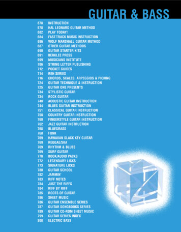
IntroductionThe Rear Panel1. Mic OutputThis XLR jack passes your mic signal to the house mixing console.2. Mic InputThis XLR jack connects a low impedance mic to the GNX2 that can be used with the Talker andVocoder effects. A mic with a cardioid pattern is recommended.3. Input JackConnect your instrument to this jack.4. Jam-A-Long JackUse a 1/8” stereo plug to connect this jack to the output of a tape or CD player. This lets you playalong with the music, or record a musical passage.5. Headphone OutputConnect stereo headphones to this jack. Be sure to set the Target System Setup mode to Directwhen listening through Headphones (see page 40 for more information on selecting the Target SystemSetup). Do not connect a mono plug to this jack, because you may damage the output driver.6. Left OutputConnect to the input of an amplifier, input of a power amp, or line input of a mixing console.7. Right OutputUse this jack in conjunction with the Left Output for stereo applications. Connect to the input of asecond amplifier, or the right input of a stereo power amp.8. Output LevelControls the overall volume level of the GNX2.9. Power SwitchTurns the power on and off.10. Power InputConnect only the provided DigiTech PSS3 power supply to this jack.11. S/PDIF OutputThis is the GNX2’s digital output . The signal at this output is in a stereo digital format, and is to beconnected to a digital S/PDIF input such as those found on digital recording devices.NOTE: Do not connect the S/PDIF output to analog auxiliary, CD, phono, or tape inputs on consumerelectronic devices. It is not compatible with these inputs.6
Introduction12. MIDI InThis jack receives all incoming MIDI data. Connect this jack to the MIDI out of a computer,sequencer, MIDI controller, or MIDI storage device.13. MIDI Out/ThruThis jack sends MIDI data from the GNX2. Connect this jack to the MIDI in of a computer, orexternal MIDI recording device. When enabled, MIDI Thru sends the same information the GNX2received at the MIDI In.14. Strain ReliefThis secures the power cord and to help prevent it from disconnecting during a performance.Getting StartedMaking ConnectionsThe GNX2 has several different connection options. You can run mono into an amp or power amp,stereo into two amps or a stereo power amp, direct into a mixing console, or any combination of these.Before connecting the GNX2, make sure both the GNX2 and the amplifier are OFF. The followingdiagrams show some examples.NOTE:The type of amplification system the GNX2 will be used with should be selected at theTarget System Setup of the Utility menu. See page 40 for more information about selectingthe Target System Setup.Mono Operation1. Connect your guitar to the input of the GNX2.2. Connect the GNX2’s left output to the instrument input on your amplifier, or to the line input of apower amp.3. Select Mono as the Output mode from the Utility menu. See page 40 for more on selecting theOutput mode.Stereo Operation1. Connect the guitar to the input of the GNX2.2. Connect the GNX2’s Left output to the input of one amplifier or channel of a power amp.3. Connect the GNX2’s right output to a second amplifier, or to a second channel of a power amp.4. Select Stereo as the Output mode from the Utility menu. See page 40 for more on selecting theOutput mode.7
IntroductionDirect to a Mixing ConsoleThe GNX2 can be connected directly to the inputs of a house PA system, or a recording console.1. Connect the guitar to the GNX2’s input.2. Connect the GNX2’s outputs to the channel inputs of the mixing console.3. If the GNX2 is to be used in Stereo mode, set the pan controls of the mixer hard left and right, andselect Stereo as the output mode from the Utility menu. See page 40 for more information on theOutput mode.S/PDIF Digital OutputThe GNX2 includes a digital S/PDIF output that connects directly to the latest digital recording devicesand sound cards. Connect the GNX2’s S/PDIF output to the S/PDIF input on your digital mixer orrecorder. You must have S/PDIF inputs on the receiving device in order to use this output. Be sure touse a 75 ohm or RCA video cable to connect from the Digital Output to a recording device. You can usethe analog and digital outputs of the GNX2 simultaneously.NOTE: Do not connect the S/PDIF output to analog auxiliary, CD, phono, or tape inputs on consumer electronic devices. It is not compatible with these inputs.Applying PowerOnce the audio connections are made, turn the GNX2’s Output Level on the rear panel all the way down(counterclockwise). Connect the PSS3 to the power jack on the back of the GNX2 and the other end toan AC outlet. Turn the power switch On. Turn the power to your amplifier(s) on. Set the amp(s) to aclean tone and set the tone controls to a flat EQ response (on most amps, this would be 0 or 5 on thetone controls). Turn the Output Level of the GNX2 up to increase the volume.8
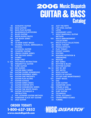
IntroductionAbout the GNX2The PresetsA preset is a named and numbered location of a programmed sound that resides in the GNX2. Presetscan be recalled with the FOOTSWITCHES or the DATA WHEEL. The GNX2 comes with 64Factory and 64 User presets. The Factory Presets do not let you store changes to them. The Userpresets let you store changes. From the factory, the 64 User presets are exact duplicates of the 64Factory presets. This lets you make your own presets without worrying about losing any of the originalpresets. When you select a preset, the name of the preset appears in the green alpha-numeric display andthe number of the preset appears in the red numeric display. The User LED to the right of the numericdisplay lights indicating the User preset is active. The Factory LED lights indicating a Factory preset isactive.Preset NameNAMESPreset Number64LEDs Indicate Whether a Useror Factory Preset is ActivePerformance ModeWhen you first apply power to the GNX2, it powers up in Performance mode. This is the mode usedwhile you are performing. While in Performance mode, the display shows the selected preset’s name andnumber. The vertical LEDs on the Matrix indicate which effects are active for the selected preset. FromPerformance mode, you have access to all of the GNX2’s presets.Preset ModePreset Mode is the factory default operation mode when the GNX2 is first powered up. In Preset mode,Footswitches 1-4 select presets in the current bank. The Mode footswitches are used to select the 16User Banks. Successive presses of the MODE footswitches advances through all User/Factory Banks.Pressing and holding a MODE footwitches scrolls through the User Banks. Once a Bank has been selected, a preset within that bank needs to be selected. If a preset is not selected within 5 seconds, the GNX2returns to the previous bank and preset.FX ModeFX Mode is another mode of operation that can be used during a performance. The FX MODE button(located to the right of the Data Wheel) is used to switch between Preset and FX Modes. When FXMode is active, the FX MODE button lights. In FX MODE, the 1-4 Footswitches turn on and off theeffects. Footswitch 1 switches between the Green, Red, and Yellow amp channels. Footswitch 2 turns theChorus/Mod Effects module on and off. Footswitch 3 turns the Delay on and off. Footswitch 4 turns theReverb on and off. The Mode footswitches are used to navigate through all of the GNX2’s presets.As an added feature, the Delay footswitch can be used as a tap-tempo switch for setting the delay timeduring live performance. While the delay is on, press and hold the Delay footswitch while in FX Mode toturn it into a tap-tempo delay switch. Press and hold it again to change it back to a Delay on and off9
IntroductionThe FootswitchesThe GNX2 1-4 footswitches are primarily used to select presets or turn on and off effects, depending onwhich mode is selected. However, these footswitches are also used to access other GNX2 functions. Forexample, pressing Footswitches 1 and 2 simultaneously, or pressing the lit Footswitch (in Preset mode)bypasses the the current preset. Pressing Footswitches 2 and 3 simultaneously accesses the Tuner mode.Pressing Footswitches 3 and 4 simultaneously activates the Learn-A-Lick mode. In Learn-A-Lick mode,Footswitches 1-4 control various Learn-A-Lick functions.The Expression PedalAs you go through the different presets in the GNX2, you will find that the expression pedal has differentfunctions.The Expression Pedal can control three different parameters in each Preset. Rock theExpression Pedal back and forth to change the values of the assigned parameters. The pedal can controlassigned minimum and maximum values (stop points) for each parameter. The Expression Pedal alsoincludes a feature called V-Switch that allows you to override the Parameters assigned to the ExpressionPedal and replace them with the Wah effect. See page 37 for more information on assigning theExpression Pedal.Bypass ModeThe GNX2 presets can be bypasse
The DigiTech GNX2,is the most advanced guitar processor of its kind. Thanks to the highly advanced tech-nology provided by GeNetX ,and the extreme horsepower contained in the Audio DNA DSP engine, you now have the tools to literally create your own guitar amplifier and speaker cabinet models. All of this