Transcription
www.orionbms.comOrion 2 BMS Operation ManualThe Orion BMS 2 by Ewert Energy Systems is the second generation of the Orion BMS. TheOrion BMS 2 is designed to manage and protect Lithium ion battery packs and is suitable for use inelectric, plug-in hybrid and hybrid electric vehicles as well as stationary applications.Major key additions in the Orion 2 BMS are: Significantly improved cell voltage measurement accuracy & resolution (0.1mV resolution) Lighter weight, smaller and more optimized mechanical design Compatibility with both 12-volt and 24-volt power supplies Ability to directly drive contactors on select outputs (limitations apply) Integrated J1772 & CHAdeMO charging interface support Significant algorithm improvements Expanded diagnostic capabilities Significantly improved multi-unit operation with remote modules New inputs and outputs Up to 8 thermistor inputs now directly on the BMS (previously 4)
Orion BMS 2 Operation ManualTable of ContentsOverview of Theory of Operation. 4Setting up the BMS . 6Wiring . 6Software . 6Testing . 6How the Orion BMS 2 Works. 7Changing and Uploading Settings . 7Basic Data Collection . 7CHARGE and READY Modes . 10Charge Interlock . 10Charge and Discharge Current Limits . 11How the BMS Calculates Current Limits . 12Selecting Current Limit Settings . 14State of Charge Calculation. 17Why SOC Correction Drifts Happen . 19Determining State of Charge Correction Drift Points. 22Temperature Capacity Reduction . 24Lifetime Capacity Loss Tracking . 24State of Health Calculation . 25Internal Resistance . 26How the BMS Calculates Internal Resistance. 27Determining Nominal Resistance . 27Isolation Fault Detection . 30Controlling Loads and Chargers . 32Digital On/Off Outputs (Relay Outputs). 32Charge Enable Output Flow Chart . 35Discharge Enable Output Flow Chart . 36Charger Safety Output Flow Chart . 38CANBUS Communication. 39Analog 5v Outputs . 392Document Revision: 1.0Last Updated: 1/9/2018
Orion BMS 2 Operation ManualHow Balancing Works . 40Busbar Compensation . 44Thermal Management and Fan Controller . 47Multi-Purpose Inputs . 48Multi-Purpose Output / Multi-Purpose Enable . 49J1772 EVSE Interface . 51CHAdeMO Interface . 52Collected Statistics (Cell Warranty Data) . 53Lifetime Parameter Tracking . 53Battery Histogram Data. 55Internal Event Log. 56Additional Data Logging Methods . 57Failure Mitigation . 58Understanding Failure Modes . 62Diagnostic Trouble Codes. 643Document Revision: 1.0Last Updated: 1/9/2018
Orion BMS 2 Operation ManualOverview of Theory of OperationThe Orion BMS 2 protects and monitors a battery pack by monitoring several sensors and uses severaloutputs to control charge and discharge into the battery. The BMS measures inputs from cell voltagetaps, the total pack voltage tap, a hall effect current sensor and thermistors. Using the programmedsettings, the BMS then controls the flow of current into and out of the battery pack through broadcastingcharge and discharge current limits (via the CANBUS or via analog reference voltages) or via simpleon/off digital signals depending on which style is appropriate for the application. The BMS relies on theuser to provide external controls that respect the current limits set by the BMS to protect the batteriesas the BMS does not have integrated switches. During and immediately after charging, the BMS willbalance the cells using internal shunt resistors based on the programmed settings.The Orion BMS monitors each individual cell tap to ensure that cell voltages are not too high or too low(in accordance with the values programmed in). Using the temperatures, cell voltages, the amperagegoing in and out of the pack (provided by the current sensor) and programmed values in the batterypack profile the BMS calculates the pack and individual cell’s internal resistance, and open cellvoltages. From those calculations, the maximum charge and discharge current limits are determinedand adjustments are made to the pack’s calculated state of charge if necessary. These calculations arealso used in monitoring the health of the pack. Charge and discharge current limits are provided on the4Document Revision: 1.0Last Updated: 1/9/2018
Orion BMS 2 Operation ManualCANBUS and can be programmed to trigger on/off digital outputs to allow or deny charging anddischarging of the battery pack.The BMS also performs other functions such as cell balancing by removing charge from cells which arehigher than the rest of the battery pack. The BMS will interface with J1772 AC charging stations as wellas off board CHAdeMO chargers.5Document Revision: 1.0Last Updated: 1/9/2018
Orion BMS 2 Operation ManualSetting up the BMSWiringPlease see the wiring manual for information regarding wiring the BMS into the application. The wiringmanual can be downloaded from www.orionbms.com/downloads.SoftwarePlease see the software manual for information on setting up specific software parameters and batteryprofile information. The BMS must be connected to a personal computer using the CANdapter (CAN toUSB adapter) and programmed using the Orion BMS software utility before it can be used. The settingsprofile must be setup correctly for the specific battery used and the application. The settings profilecontrols parameters such as maximum and minimum cell voltages and external interfaces such as CANinterfaces and digital I/O. The software and software manual can be found atwww.orionbms.com/downloads.TestingAfter setting up the BMS or making any changes to the BMS settings or external hardware, the entiresetup should be tested to ensure that it is functioning properly. This is particularly important withrespect to any potentially catastrophic failures, such as failures that would lead to over charge or overdischarge. It is the responsibility of the user to verify that the BMS is programmed and operatingcorrectly with the application. At a minimum, the user should perform testing to ensure the followingconditions are working properly:1. Ensure that the BMS is setup in such a manner that testing will not cause immediate danger tothe battery pack.2. Ensure that cell voltages are being read correctly and that no critical fault codes are present.The BMS cannot properly read cell voltages if unit and batteries are not wired correctly. Doublechecking cell voltages with a multimeter will help verify that the BMS is measuring voltagescorrectly.3. Ensure that the current sensor is reading the correct values and that current going into thebattery pack (charge) shows up as negative and that current leaving the battery pack(discharge) shows up as positive.4. If the charge enable, discharge enable, or charger safety relays are used, ensure that they areoperating by carefully monitoring the battery pack during the first full cycle (full charge anddischarge) to check that cutoffs are properly working for all used outputs. Keep in mind thatconditions are usually only triggered when the pack is totally charged or totally discharged.Particular attention should be paid to make sure the BMS properly shuts off a battery charger ifconnected or any other source or load.6Document Revision: 1.0Last Updated: 1/9/2018
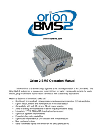
Orion BMS 2 Operation Manual5. If charge and discharge limits are used (either via CAN or analog outputs) ensure that theybehave as expected over the first full charge and discharge cycle and that any devices thatmust enforce those limits are actually respecting them.How the Orion BMS 2 Works(Detailed Theory of Operation)Changing and Uploading SettingsThe Orion BMS 2 must be programmed in order to operate. A complete collection of settings is called aBattery Profile. Profiles are edited on a personal computer using the Orion BMS 2 Utility software andthen are “uploaded” to the BMS via CANBUS. Profiles can optionally be locked into the BMS with apassword to prevent end users from modifying or viewing settings. Uploading and downloading settingsrequire the use of a CANdapter (a CAN to USB adapter) sold by Ewert Energy Systems. Batteryprofiles can also be downloaded back from the BMS to be edited.Basic Data CollectionThe Orion BMS 2 collects data from a number of different sensors for use in calculations and decisionmaking.Cell Voltages - Each cell’s voltage is measured approximately every 30 mS by sensing the voltage atthe cell voltage tap connector. The BMS measures the difference in voltage from one tap wire to thenext to measure a cell's voltage. Unless busbar compensation has been configured, the BMS willdisplay and use the actual measured values for cell voltages (otherwise compensated values are used).Only the cell voltages which the BMS has been programmed to monitor in the cell population table aremonitored while the other cell voltages are ignored.Current (Amperage) - The current going in and out of the battery pack is measured every 8mS usingthe external hall effect sensor. The hall effect sensor is clamped around a wire carrying all current intoand out of the battery pack and converts the measured amperage into two 0 - 5 volt analog voltages.One channel is used for measuring smaller amperages to ensure high resolution for small currents andthe other channel is used for measuring larger currents. These two analog voltages are measured bythe BMS and converted into an amperage value which the BMS uses for various calculations. Thediagram below demonstrates how the feedback voltage from the larger channel correlates with theactual current being measured (a 500A sensor is used for demonstration purposes).7Document Revision: 1.0Last Updated: 1/9/2018
Orion BMS 2 Operation ManualThis figure demonstrates the relationship between the voltage output and current measured on the current sensorThe currents sensors sold with the Orion BMS are available in sizes up to 1000A. The BMS can beconfigured to use 2 parallel current sensors to measure amperages up to 2000A, however themaximum recommended size is 1000A. Current sensors sold with the BMS are able to measureamperages up to 120% of their rated maximum, though accuracy is reduced above 100%.Current sensor data is used in calculating the battery pack’s state of charge (via coulomb counting) andensuring that the attached application is staying within the correct current limits. The measured currentis also used in calculating the internal resistance and health of the cells in the battery pack.Temperatures - The BMS measures up to 8 thermistors directly connected to the main unit todetermine the average (rough) temperature of the battery pack as a whole. If additional remotemodules are used for monitoring additional cell taps, an additional 8 thermistors per remote module areprovided. If a greater number of temperature sensing inputs are required, the BMS can be connected toup to 10 thermistor expansion modules which measure up to 80 thermistors each, allowing the BMS tomonitor over 800 temperature inputs. Thermistors on the main unit, remote modules and any expansionmodules may be left ‘unpopulated’ meaning that the BMS will ignore the value of those thermistors.This allows the BMS to be configured to use as few or as many thermistors as necessary. One of thethermistors may be specified as an ambient temperature thermistor which, if enabled, allows the BMSto determine the effectiveness of turning on an optional external battery cooling fan. This feature alsoallows the BMS to use the same fan to blow warm air over the batteries if the batteries are cold andambient air is warmer.Total Pack Voltage – The Orion BMS 2 measures the total pack voltage by adding the individual cellvoltages together. This method differs from previous revision of the Orion BMS and produces much8Document Revision: 1.0Last Updated: 1/9/2018
Orion BMS 2 Operation Manualmore accurate total pack voltage numbers. No additional wires are necessary for monitoring the packvoltage.Isolation Fault Sensor - Unless ordered without this feature, the Orion BMS 2 has a sensor thatmeasures the electrical isolation between the battery pack and the chassis of the vehicle. This sensor isused to ensure that a breakdown in electrical isolation has not occurred between the chassis and a livepart of the battery pack. Specifically, it measures the isolation between the input power ground (pin 12on the BMS Main I/O connector) and the cell tap 1- (negative) on the first cell group connector. Aninternal isolation relay allows this circuit to be disabled by software or the unit can be special orderedwith this feature permanently enabled or permanently disabled. See the “Isolation Fault Detection”section below for more information on this sensor.Other Inputs - The BMS has the ability to sense the status of the 3 power supplies (Always On,READY power and CHARGE power) which determine what mode the BMS is in. The BMS also has 3multi-purpose inputs which can be used for various functions including interfacing with J1772 chargingstations, and an analog voltage input used to monitor the health of a battery cooling fan (optional).9Document Revision: 1.0Last Updated: 1/9/2018
Orion BMS 2 Operation ManualCHARGE and READY ModesThe BMS has two primary modes of operation: Charge Mode and Ready Mode. The BMS will enterinto Charge Mode any time 12 - 24v is applied to the CHARGE power pin (Main I/O pin 3), regardlessof whether READY power is also present or not.The following functions are enabled (or change) when the BMS is in Charge Mode:1. The charger safety output is allowed to turn on if enabled and if all criteria have been met.2. The BMS will cap the state of charge to the value specified as the "Charged SOC" percentage.Even if the battery is charged in such a way that would normally cause the SOC to rise abovethis value, the value will not exceed the "Charged SOC parameter" while the BMS is in chargemode.3. When any cell voltage hits the maximum cell voltage (resulting in the BMS turning the chargeroff), the BMS will immediately adjust the state of charge to the "Charged SOC" value since theBMS knows that the battery pack is fully charged at this time.4. The cell balancing algorithm is enabled and will begin balancing as soon as any cell voltagegoes above the "Start Balancing" voltage. Balancing will continue until all cell voltages arebalanced to within the balance delta voltage parameter. See the “How Balancing Works” sectionfor more information on cell balancing.5. Certain CANBUS messages may be transmitted or not transmitted depending on whether theBMS is in CHARGE mode or not (if configured).6. The maximum possible current limit for charging is limited to the "Maximum Amperage WhileCharging" parameter available on the “Charge Limits” profile settings tab.7. The maximum allowable cell voltage is limited to the "Max. Voltage While Charging" parameteravailable on the “Cell Settings” profile settings tab.Charge InterlockIn the event that the BMS detects both CHARGE and READY power at the same time, the BMS canoptionally be configured to indicate it is in an interlock mode. Interlock mode is generally used toprevent a vehicle from driving away while it is still plugged in. The BMS can also be configured to entercharge interlock mode when a connector is detected in the J1772 inlet via the proximity detect. Whenthe BMS detects a condition where either the J1772 inlet is active or both CHARGE power and READYpower are present at the same time, a few things can happen:1.2.3.4.The BMS can be configured to set a temporary (non-latching) fault code (P0ACA).The BMS can be configured to not allow any discharge while in this mode.The BMS can transmit the status of charge interlock via one or more CANBUS messages.One of the multi-purpose outputs can be configured to indicate the status of charge interlock.10Document Revision: 1.0Last Updated: 1/9/2018
Orion BMS 2 Operation ManualNote: While the BMS can accurately detect the presence of CHARGE and READY power, the BMScannot detect a cord which is plugged into a vehicle that is not powered. It is often best to useadditional external systems, such as the J1772 charging standard, to prevent the vehicle from drivingaway while a cord is connected but not powered.Note: If desired, the charge interlock feature can be disabled in the settings profile such that the BMSwill operate normally when CHARGE and READY power are both supplied at the same time. This isaccomplished via the “Fault Settings” tab in the profile settings.Charge and Discharge Current LimitsFor Lithium-ion cells, limiting cell voltages to within a specified voltage range is essential for protectingthe cell from damage. However, there are many other parameters, such as temperature and currentlimits, which must also be monitored to protect the cells. To be able to control more than one parameterat once, the BMS incorporates different parameters into a maximum allowable charge and dischargecurrent limit. Charge and discharge limits can be thought of as the realistic maximum amperage limitsthat a battery can discharge or charge at any given moment (expressed in 1 amp increments). Currentlimits are especially useful for variable current applications such as electric vehicles, because theyallow these applications to slowly reduce current as a battery pack is emptied and therefore increasethe usable range of a battery pack.The charge and discharge current limits can be transmitted digitally from the BMS to other devices ifthe external device supports this. For example, most CANBUS enabled motor controllers and CANBUSenabled battery chargers support this. When a motor controller receives the current limit from the BMS,the motor controller knows that it cannot exceed the maximum current limit sent by the BMS even if theoperator of the throttle calls for more power. Because the BMS incorporates many factors into themaximum current limit, ensuring the current does not exceed this calculated current limit also ensuresall the other associated battery parameters (such as minimum cell voltage, temperature, maximum Crate, minimum state of charge, etc) are enforced.While some motor controllers or chargers don’t support CANBUS, they may support an analog voltageinput that represents the current limit. The Orion BMS has 0 to 5 volt analog outputs which representthe maximum current limits in an analog voltage. This operates the same way as the CANBUS support,but is less accurate and less desirable than CANBUS control.When a load does not support variable current limiting and can only be turned fully on or fully off (suchas a resistive load or a non-intelligent DC to AC inverter), the BMS must operate in an on/off mode tocontrol the load. In this case, the BMS still uses the charge and discharge current limits as the basis formaking decisions about when the BMS will allow charge or discharge. The relay outputs will turn offwhenever the associated current limit drops to 0 amps at any point (for example, the Discharge Enable11Document Revision: 1.0Last Updated: 1/9/2018
Orion BMS 2 Operation Manualrelay will turn off when the Discharge Current Limit drops to 0A). The status of these relay outputs areavailable to be included in CANBUS messages if they need to be sent digitally. The exact conditions forthis are discussed in the Relays section of this manual.How the BMS Calculates Current LimitsThe BMS continuously calculates both the Charge Current Limit (the amount of current, expressed inamps, that can safely go into the pack at this precise moment) and Discharge Current Limit (the amountof current, expressed in amps, that can safely leave the pack at this precise moment). Thesecalculations are performed based on the data and parameters entered on the Charge Limits andDischarge Limits pages in the profile settings section of the utility.In principle, both the Discharge Current Limit and Charge Current Limit are calculated the same waywith the clear difference that Charge Current Limit is looking to limit the maximum voltage a cell canreach whereas the Discharge Current Limit is to limit the minimum cell voltage. Because of thissignificant similarity, all criteria described below are for the Discharge Current Limit to simplify theexplanation (though the information for Charge Current Limit can be easily extrapolated).The BMS starts the current limit calculation by loading the maximum continuous discharge current limitprogrammed into the BMS (which is the highest current that the cell can safely sustain for extendedamounts of time). This value is provided by the cell manufacturer and should not be exceeded orincreased beyond the manufacturer's recommendations (though there are certain cases where it maybe advisable to reduce this limit to extend the lifespan of the cells).Some cells support short pulses at higher currents than their maximum continuous rating (such as ahigher amperage pulse for up to 10 seconds). For many cells, after a pulse occurs, a rest period isrequired for the cell to recover without damage. If pulse currents are enabled in the BMS profile, theBMS will determine if the battery pack can accept a pulse or not. If the BMS determines that the batterypack is in a condition where it can accept a pulse, the maximum current limit is increased to themaximum pulse current limit indicating that the battery may draw the pulse current. Otherwise, it is leftat the maximum continuous rating. If the BMS determines that a pulse in amperage has recentlyoccurred and the battery pack is still in the rest period recovering from a previous pulse current, theBMS will instead lower the maximum current limit to the resting current limit programmed into the BMSprofile to allow the battery pack to recover safely.The above calculations establish the absolute maximum allowable current under ideal conditions.However, the BMS may reduce those limits further for several reasons. If any of the below calculationsresult in a calculated current limit lower than the absolute maximum, the BMS will use the lowest of thecalculated limits as the current limit.1. Temperature - The BMS will lower the current limits based on the temperature limitationsprogrammed into the BMS profile. The temperature limits are established in the settings profilewith a maximum amperage limit for every 5 degrees Celsius (the BMS will use the closesttemperature to the actual pack temperature when applying the limits). Amperage limits are12Document Revision: 1.0Last Updated: 1/9/2018
Orion BMS 2 Operation Manual2.3.4.5.typically reduced for both high and low temperatures. Minimum and maximum battery operatingtemperatures for cells are enforced by the separate maximum / minimum temperatureparameters. Setting maximum and minimum temperature values for both limits isextremely important to ensure that the battery cells are not operated outside ofspecification. Operating batteries outside of the manufacturer specified temperatureranges can cause permanent, irreversible damage to them and may result in risk of fire.State of Charge - The BMS can be setup to lower the current limits based on the State ofCharge of the battery pack. Just like the temperature settings above, the BMS can reduce themaximum current limits based on the programmed values in the profile settings. In this case, forthe discharge current limit, a state of charge is specified where to begin reducing the dischargecurrent limit along with a value of amps per percentage state of charge. This is most commonlyused to reduce the amperage limits when a vehicle is approaching a low state of charge such asto slow a vehicle when the battery is low. For most applications, this feature is not required andmay be disabled to prevent possibly errant SOC calculations from altering the usable range ofthe pack unless there is a specific reason for enabling it. This feature may be required, however,if the battery pack must be kept within a certain state of charge. Typically, it is advisable to limitcharging based on the maximum cell voltage as opposed to a specific State of Charge percentas this will generally be more reliable.Cell Resistance (based on each individual cell voltage) - The BMS will measure the voltageand resistance of each individual cell in the battery pack and perform a calculation for how muchcurrent that cell can accept (charge) or provide (discharge). The BMS will reduce the overallpack current limit based on the weakest cell to ensure that, if a load or charge is placed on thebattery pack, the load or charge would not cause any cell to exceed the maximum cell voltageor drop below the minimum cell voltage. This calculation uses the internal resistance of the celland the open circuit voltage of the cell. This can be thought of as an ohm’s law calculationwhere the BMS is solving for the maximum possible amperage that will still keep the cell voltageinside the safe range. This calculation preemptively keeps the cell voltage within specifications.Pack resistance (based on pack voltage) – Pack voltage limits are optional because theBMS is already enforcing individual cell voltage limits which will inherently maintain aminimum and maximum pack voltage (minimum cell voltage x number of cells andmaximum cell voltage x number
Orion BMS 2 is designed to manage and protect Lithium ion battery packs and is suitable for use in electric, plug-in hybrid and hybrid electric vehicles as well as stationary applications. Major key additions in the Orion 2 BMS are: Significantly improved cell voltage measurement accuracy & resolution (0.1mV resolution) Lighter weight, smaller and more optimized mechanical design Compatibility .