Transcription
Orion: Google’s Software-Defined NetworkingControl PlaneAndrew D. Ferguson, Steve Gribble, Chi-Yao Hong, Charles Killian, Waqar Mohsin,Henrik Muehe, Joon Ong, Leon Poutievski, Arjun Singh, Lorenzo Vicisano,Richard Alimi, Shawn Shuoshuo Chen, Mike Conley, Subhasree Mandal,Karthik Nagaraj, Kondapa Naidu Bollineni, Amr Sabaa, Shidong Zhang,Min Zhu, and Amin Vahdat, sentation/fergusonThis paper is included in theProceedings of the 18th USENIX Symposium onNetworked Systems Design and Implementation.April 12–14, 2021978-1-939133-21-2Open access to the Proceedings of the18th USENIX Symposium on NetworkedSystems Design and Implementationis sponsored by
Orion: Google’s Software-Defined Networking Control PlaneAndrew D. Ferguson, Steve Gribble, Chi-Yao Hong, Charles Killian, Waqar MohsinHenrik Muehe, Joon Ong, Leon Poutievski, Arjun Singh, Lorenzo Vicisano, Richard AlimiShawn Shuoshuo Chen, Mike Conley, Subhasree Mandal, Karthik Nagaraj, Kondapa Naidu BollineniAmr Sabaa, Shidong Zhang, Min Zhu, Amin VahdatGoogleorion-nsdi2021@google.comAbstractWe present Orion, a distributed Software-Defined Networking platform deployed globally in Google’s datacenter(Jupiter) and Wide Area (B4) networks. Orion was designedaround a modular, micro-service architecture with a centralpublish-subscribe database to enable a distributed, yet tightlycoupled, software-defined network control system. Orionenables intent-based management and control, is highly scalable and amenable to global control hierarchies.Over the years, Orion has matured with continuouslyimproving performance in convergence (up to 40x faster),throughput (handling up to 1.16 million network updates persecond), system scalability (supporting 16x larger networks),and data plane availability (50x, 100x reduction in unavailable time in Jupiter and B4, respectively) while maintaininghigh development velocity with bi-weekly release cadence.Today, Orion enables Google’s Software-Defined Networks,defending against failure modes that are both generic to largescale production networks as well as unique to SDN systems.1IntroductionThe last decade has seen tremendous activity in SoftwareDefined Networking (SDN) motivated by delivering new network capabilities, fundamentally improving network reliability, and increasing the velocity of network evolution. SDNstarts with a simple, but far-reaching shift in approach: moving network control, such as routing and configuration management, from individual hardware forwarding elements to acentral pool of servers that collectively manage both real-timeand static network state. This move to a logically centralized view of network state enables a profound transition fromdefining pairwise protocols with emergent behavior to distributed algorithms with guarantees on liveness, safety, scale,and performance.For example, SDN’s global view of network state presentsan opportunity for more robust network verification and intentbased networking [16, 17]. At a high level, SDN affords theopportunity to transition the network from one consistentstate to another, where consistency can be defined as policyUSENIX Associationcompliant and blackhole-free. This same global view andreal-time control enables traffic engineering responsive totopology, maintenance events, failures, and even fine-grainedcommunication patterns such that the network as a wholecan operate more efficiently and reliably [2, 12, 13]. There isongoing work to tie end host and fabric networking together toensure individual flows, RPCs, and Coflows meet higher-levelapplication requirements [1,11,22], a capability that would behard or impossible with traditional protocols. Perhaps one ofthe largest long-term benefits of SDN is support for softwareengineering and qualification practices to enable safe weeklysoftware upgrades and incremental feature delivery, whichcan hasten network evolution by an order of magnitude.While the promise of SDN is immense, realizing thispromise requires a production-grade control plane that meetsor exceeds existing network performance and availability levels. Further, the SDN must seamlessly inter-operate with peerlegacy networks as no network, SDN or otherwise, operatessolely in its own tech island.In this paper, we describe the design and implementationof Orion, Google’s SDN control plane. Orion is our secondgeneration control plane and is responsible for the configuration, management, and real-time control of all of our datacenter (Jupiter [28]), campus, and private Wide Area (B4 [15])networks. Orion has been in production for more than fouryears. The SDN transition from protocols to algorithms, together with a micro-services based controller architecture,enables bi-weekly software releases that together have notonly delivered over 30 new significant capabilities, but alsohave improved scale by a factor of 16, availability by a factorof 50x in Jupiter and 100x in B4, and network convergencetime by a factor of 40. Such rapid evolution would have beenhard or impossible without SDN-based software velocityOrion’s design centers around a constellation of independent micro-services, from routing to configuration management to network management, that coordinate all state throughan extensible Network Information Base (NIB). The NIBsequences and replicates updates through a key-value abstraction. We describe the performance, semantic, and availability18th USENIX Symposium on Networked Systems Design and Implementation83
requirements of the NIB and the development model that allows dozens of engineers to independently and simultaneouslydevelop, test, and deploy their services through well-defined,simple, but long-lived contractual APIs.While Orion has been a success at Google, neither ourdesign nor the SDN approach are panaceas. We describe fourkey challenges we faced in Orion—some fundamental to SDNand some resulting from our own design choices—along withour approach to addressing them:#1: Logically centralized control require fundamentallyhigh performance for updates, in-memory representationof state, and appropriate consistency levels among looselycoordinating micro-service SDN applications.#2: The decoupling of control from hardware elementsbreaks fate sharing in ways that make corner-case failure handling more complex. In particular, control software failuredoes not always mean the corresponding hardware elementhas failed. Consider the case where the control software runsin a separate physical failure domain connected through anindependent out-of-band control network. Either the physicalinfrastructure (control servers, their power or cooling) or control network failure can now result in at least the perceptionof a sudden, massively correlated failure in the data plane.#3: Managing the tension between centralization and faultisolation must be balanced carefully. At an extreme, one couldimagine a single logical controller for all of Google’s networkinfrastructure. At another extreme, one could consider a singlecontroller for every physical switch in our network. Whileboth extremes can be discarded relatively easily, finding theappropriate middle ground is important. On the one hand,centralization is simpler to reason about, implement, andoptimize. On the other, a centralized design is harder to scaleup vertically and exposes a larger failure domain.#4: In a global network setting, we must integrate existingrouting protocols, primarily BGP, into Orion to allow interoperation with non-SDN peer networks. The semantics ofthese protocols, including streaming updates and fate sharingbetween control and data plane, are a poor match to our choiceof SDN semantics requiring adaptation at a number of levels.This paper presents an introductory survey of Orion. Weoutline how we manage these concerns in its architecture,implementation, and evolution. We also discuss our production experiences with running Orion, pointing to a number ofstill open questions in SDN’s evolution. We will share moredetails and experiences in subsequent work.2Related WorkOrion was designed with lessons learned from Onix [18].Unlike Onix’s monolithic design with cooperative multithreading, Orion introduced a distributed design with eachapplication in a separate process. While Onix introduceda NIB accessible only to applications in the same process,Orion’s is accessible by applications within and across domains, providing a mechanism for hierarchy, which few exist-84ing controllers incorporate (Kandoo [35] being an exception).Hierarchy enabled fabric-level drain sequencing 1 and optimalWCMP-based (Weighted Cost Multi-Pathing) routing [36].We distribute Orion’s logic over multiple processes forscalability and fault-tolerance, a feature shared with otherproduction-oriented controllers such as ONOS [4] and OpenDaylight [24], and originally proposed by Hyperflow [30].Unlike our previous design, Orion uses a single configurationfor all processes, applied atomically via the NIB, precludingerrors due to inconsistent intended state.Orion uses database-like tables to centrally organize stateproduced and consumed by SDN programs, a feature sharedwith a few other OpenFlow controllers such as ONOS [4],Flowlog [27], and Ravel [32]. The combination of all ofthese techniques – hierarchy, distribution, and database-likeabstractions – allowed Orion to meet Google’s availabilityand performance requirements in the datacenter and WAN.While Orion is an evolution in the development of OpenFlow controllers, its modular decomposition of network functions (e.g., routing, flow programming, switch-level protocols,etc.) is a design goal shared with pre-OpenFlow systems suchas 4D/Tesseract [33] and RCP [6]. Single-switch operatingsystems that similarly employ microservices and a centralizeddatabase architecture include Arista EOS [3] and SONiC [25].3Design PrinciplesWe next describe principles governing Orion’s design. Weestablished many of these during the early stages of buildingOrion, while we derived others from our experience operatingOrion-based networks. We group the principles into threecategories: environmental – those that apply to productionnetworks, architectural – those related to SDN, and implementation – those that guide our software design.3.1Principles of production networksIntent-based network management and control. Intentbased networks specify management or design changes bydescribing the new intended end-state of the network (the“what”) rather than prescribing the sequence of modificationsto bring the network to that end-state (the “how”). Intentbased networking tends to be robust at scale, since high-levelintent is usually stable over time, even when the low-levelstate of network elements fluctuates rapidly.For example, consider a situation where we wish to temporarily “drain” (divert traffic away from) a cluster while wesimultaneously add new network links to augment the ingressand egress capacity of the cluster. As those new links turnup, the stable drain intent will also apply to them, causing theunderlying networking control system to avoid using them.In Orion, we use an intent-based approach for updating thenetwork design, invoking operational changes, and addingnew features to the SDN controller. For example, we capture1 Fabric-leveldrain sequencing refers to redirecting traffic in a loss-freemanner, throughout the fabric, away from a target device being drained.18th USENIX Symposium on Networked Systems Design and ImplementationUSENIX Association
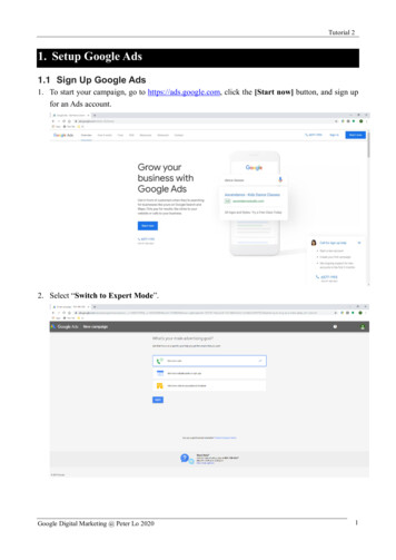
intended changes to the network’s topology in a model [26],which in turn triggers our deployment systems and operational staff to make the necessary physical and configurationchanges to the network. As we will describe later, Orionpropagates this top-level intent into network control applications, such as routing, through configuration and dynamicstate changes. Applications react to top-level intent changesby mutating their internal state and by generating intermediate intent, which is in turn consumed by other applications.The overall system state evolves through a hierarchical propagation of intent ultimately resulting in changes to the programmed flow state in network switches.Align control plane and physical failure domains. Onepotential challenge with decoupling control software fromphysical elements is failure domains that are misaligned or toolarge. For misalignment, consider the case in which a singleSDN controller manages network hardware across portions oftwo buildings. A failure in that controller can cause correlatedfailures across two buildings, making it harder to meet higherlevel service SLOs. Similarly, the failure of a single SDNcontroller responsible for all network elements in a campuswould constitute too large a vulnerability even if it improvedefficiency due to a centralized view.We address these challenges by carefully aligning networkcontrol domains with physical, storage, and compute domains.As one simple example, a single failure in network controlshould not impact more than one physical, storage, or compute domain. To limit the “blast radius” of individual controller failures, we leverage hierarchical, partitioned controlwith soft state progressing up the hierarchy (§5.1). We explicitly design and test the network to continue correct, thoughlikely degraded, operation in the face of controller failures.3.2Principles related to an SDN controllerSDN enables novel approaches to handling failures, butit also introduces new challenges requiring careful design.The SDN controller is remote from the network switches,resulting in the lack of fate sharing but also the possibility ofnot being able to communicate with the switches.Lack of fate sharing can often be used to our advantage.For example, the network continues forwarding based onits existing state when the controller fails. Conversely, thecontroller can repair paths accurately and in a timely mannerwhen individual switches fail, by rerouting around them.React optimistically to correlated unreachability. Theloss of communication between controller and switches posesa difficult design challenge as the controller must deal withincomplete information. We handle incomplete informationby first deciding whether we are dealing with a minor failureor a major one, and then reacting pessimistically to the formerand optimistically to the latter.We start by associating a ternary health state with networkelements: (i) healthy with a recent control communication (aswitch reports healthy link and programming state with noUSENIX AssociationFigure 1: Network behavior in three cases: Normal (left): A network with healthy switches. Flows from top to bottom switches useall middle switches. Fail Closed (mid): With few switches in unknown state (grey), the controller conservatively routes around them.Fail Static (right): With enough switches in unknown state, thecontroller no longer routes around newly perceived failed switches.packet loss), (ii) unhealthy, when a switch declares itself tobe unhealthy, when neighbouring switches report unhealthyconditions or indirect signals implicate the switch, and (iii)unknown, with no recent control communication with a switchand no indirect signals to implicate the switch.A switch in the unknown state could be malfunctioning, orit could simply be unable to communicate with a controller(a fairly common occurrence at scale). In comparison, theunhealthy state is fairly rare, as there are few opportunities todiagnose unequivocal failure conditions in real time.2The controller aggregates individual switch states into anetwork-wide health state, which it uses to decide betweena pessimistic or an optimistic reaction. We call these FailClosed and Fail Static, respectively. In Fail Closed, the controller re-programs flows to route around a (perceived) failedswitch. In Fail Static, the controller decides not to react to aswitch in an unknown, potentially failed, state, keeping trafficflowing toward it until the switch state changes or the networkoperator intervenes. Figure 1 illustrates an example of normaloperation, Fail Closed reaction, and Fail Static condition.In Fail Static, the controller holds back from reacting toavoid worsening the overall state of the network, both interms of connectivity and congestion. The trade-off betweenFail Closed and Fail Static is governed by the cost/benefitimplication of reacting to the unknown state: if the elementin the unknown state can be avoided without a significantperformance cost, the controller conservatively reacts to thisstate and triggers coordinated actions to steer traffic awayfrom the possible failures. If the reaction would result in asignificant loss in capacity or loss in end-to-end connectivity,the controller instead enters Fail Static mode for that switch.In practice we use a simple “capacity degradation threshold”to move from Fail Closed to Fail Static. The actual thresholdvalue is directly related to: (1) the operating parameters ofthe network, especially the capacity headroom we typicallyreserve, for example, to support planned maintenance; (2) thelevel of redundancy we design in the topology and control2 It is not common for a software component to be able to self-diagnose afailure, without being able to avoid it in the first place, or at least repair it.Slightly more common is the ability to observe a failure from an externalvantage point, e.g. a neighboring switch detecting a link “going down.”18th USENIX Symposium on Networked Systems Design and Implementation85
domains. We aim to preserve a certain amount of redundancyeven in the face of capacity degradation.In our experience, occurrences of Fail Static are fairly common and almost always appropriate, in the sense that they arenot associated with loss of data plane performance. Often FailStatic is triggered by failures in the control plane connectivitybetween the SDN controller and the network elements, or bysoftware failures in the controller. Neither of these directlyaffect the data plane health.We view the ability to Fail Static as an advantage of SDNsystems over traditional distributed-protocol systems. Distributed systems are also subject to some of the failures thatcould benefit from a Fail Static response. However, they arenot easily amenable to realize a Fail Static behavior becausethey only have a local view. It is far easier for a centralizedcontroller to assess if it should enter Fail Static when it canobserve correlated network failures across its entire domain.Exploit both out-of-band and in-band control planeconnectivity. In a software-defined network, a key consideration is connectivity between the “off box” controller andthe data plane switches. We must solve the bootstrap problem of requiring a functioning network to establish baselinecontrol. Options include using: i) the very network being controlled (“in-band”) or ii) a (physically or logically) separate“out-of-band” network. While a seemingly simple question,considerations regarding pure off-box SDN control, circular dependencies between the control and dataplane network,ease of debuggability, availability, manageability and cost ofownership make this topic surprisingly complex.The simplest approach is to have a physically separate outof-band control/management plane network (CPN) for communication between controller and switches orthogonal tothe dataplane network. This approach cleanly avoids circulardependencies, keeping the control model simple and enablingeasy recovery from bugs and misconfiguration. Ideally, wewould like the out-of-band control network to be highly available, easy to manage and maintain, and cost effective. Inthe end, a separate CPN means installing and operating twodistinct networks with different operational models and independent failure characteristics. While failure independenceis often a desirable property, subtle or rare failure scenariosmean the entire data plane could go down if either the dataplane or control plane fails. We describe our choice of hybridCPN for Orion in §5.3.3Software design principlesEnabling a large-scale software development environmentwas a key motivation for building our own SDN controller.Critical to the success of SDN is the ability to safely deploynew functionality across the network incrementally with frequent software releases. This, in turn, means that a substantialteam of engineers must be able to develop multiple independent features concurrently. The need to scale engineeringprocesses led to a modular system with a large number of86decoupled components. At the same time, these componentshad to interact with one another to realize a tightly-coupledcontrol system reflecting the structure and dynamics of network control. We achieved this goal through: a microservice architecture with separate processes ratherthan a monolithic block which we adopted in our firstgeneration SDN controller [18], for software evolvabilityand fault isolation. a central pub-sub system (NIB) for all the communicationbetween microservices, which took care of the tightlycoupled interaction across processes.Failure domain containment (§3.1) imposes an upper limitto the size of control domains. Nevertheless, we were concerned with the performance, scalability, and fault model of asingle NIB to coordinate all communication and state withina control domain. We satisfied our performance concernsthrough benchmarking efforts, and fault tolerance concernsby limiting control domain scope and the ability to fail static,including between control domains.Based on years of experience, the NIB has been one ofour most successful design elements. It manages all intercomponent communications, allows us to create a “singlearrow of time,” establishing an order among the otherwiseconcurrent events across processes. This brought significantlyuseful side effects including much improved debuggability ofthe overall system. It also allows us to store event sequences(NIB traces) in external systems and use them for offlinetroubleshooting and independent validation of subsystems,which we use in component-level regression testing.Next, we discuss the principles of intent based control,introduced in 3.1, reconciliation of state as well as the implications of various failure modes in an SDN-based system:Intent flows from top to bottom. The top level intent forthe system as a whole is the operator intent and the static configuration. As intent propagates through the system via NIBmessages, it triggers local reactions in subsystems that generate intermediate intent consumable by other sub-systems.Higher-level intent is authoritative and any intermediate intent (also known as derived state) is rebuilt from it. Theprogrammed switch state is the ground truth correspondingto the intent programmed into dataplane devices.The authoritative intent must always be reflected in theground truth. The controller ensures that any mismatch iscorrected by migrating the ground truth toward the intendedstate in a way that is minimally disruptive to existing dataplane traffic. We refer to this process as “state reconciliation”.Reconciliation is best performed in the controllerwhich has a global view since minimal disruption often requires coordination across switches such that changes aresequenced in a graceful and loop-free manner. Reconciliationis a powerful concept that allows reasoning about complexfailure modes such as Orion process restarts as well as lackof fate sharing between the data and control planes.Availability of high level intent is crucial to keep the top-18th USENIX Symposium on Networked Systems Design and ImplementationUSENIX Association
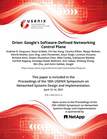
Of note, durability [14] was not a requirement for the NIB because its state could be reconstructed from network switchesand other sources in the event of a catastrophic failure.NIB Entities. The NIB consists of a set of NIB entity tableswhere each entity describes some information of interest toother applications or observers both local or external to thedomain. Some of the entity types include:Figure 2: Overview of Orion SDN architecture and core apps.down intent-based system simple. To achieve this goal weminimize the time when the intent is temporarily unavailable(e.g., because of process restarts or communication failurebetween components).4ArchitectureFigure 2 depicts the high-level architecture of Orion, and howit maps to the textbook ONF view [7]. For scalability andfault isolation, we partition the network into domains, whereeach domain is an instance of an Orion SDN controller.The data plane consists of SDN switches at the bottom.Orion uses OpenFlow [23] as the Control to Data Plane Interface (CDPI). Each switch runs an OpenFlow Agent (OFA)for programmatic control of forwarding tables, statistics gathering, and event notification. The control plane consists ofOrion Core in the center and SDN applications at the top.The control plane is physically separate from the data planeand logically centralized, providing a global view of the domain. Though logically centralized, the Orion Core controlsthe network through distributed controller processes. TheNIB provides a uniform SDN NorthBound Interface for theseapplications to share state and communicate requirements.The Orion Core is responsible for (i) translating these requirements into OpenFlow primitives to reconcile switches’programmed state with intended state and (ii) providing aview of the runtime state of the network (forwarding rules,statistics, data plane events) to applications.4.1Orion CoreThe NIB is the intent store for all Orion applications. Itis implemented as a centralized, in-memory datastore withreplicas that reconstruct the state from ground-truth on failure.The NIB is coupled with a publish-subscribe mechanism toshare state among Orion applications. The same infrastructureis used externally to collect all changes in the NIB to facilitatedebugging. The NIB must meet the following requirements: Low External Dependency. As Orion programs the network supporting all higher-level compute and storage services, it cannot itself depend on higher-level services. Sequential Consistency of Event Ordering. To simplifycoordination among apps, all apps must see events in thesame order (arrow of time [20]).USENIX Association Configured network topology. These capture the configured identities and graph relationship between various network topological elements. Examples include Port, Link,Interface, and Node tables. Network run-time state. This could be topological state,forwarding state (e.g. ProgrammedFlow table), protocol state (e.g. LLDPPeerPort table), statistics (e.g.PortStatistics table). Orion App Configuration. Each app’s configuration iscaptured as one or more NIB tables, e.g. LLDPConfig.Protocol Buffer Schema. We represent the schema foreach NIB entity as a protocol buffer message [8]. Each rowin that NIB entity table is an instantiation of this schema. Thefirst field of each entity schema is required to be a NIBHeadermessage which serves as the key for that entity. The NIB doesnot enforce referential integrity for foreign keys; however,inconsistencies fail an internal health-check.An example entity represented in the NIB is a Link entity.A link is modelled as foreign key references to Port and Nodeentities respectively. This expresses the connection betweentwo ports of two switches. Additionally, a status (up, down,or unknown), is modelled as part of the Link entity. The fullprotocol buffer is shown in the appendix.Protocol buffers allow us to reuse well-understood patternsfor schema migrations. For example, adding a new field toa table has built-in support for backward and forward compatibility during an upgrade despite some applications stillrunning with the previous schema.NIB API. The NIB provides a simple RPC API (Read,Write, Subscribe) to operate on NIB tables. The Write operation is atomic and supports batching. The Subscribe operationsupports basic filtering to express entities of interest. The NIBnotification model provides sequential consistency of eventordering. It also supports coalescing multiple updates into asingle notification for scale and efficiency reasons.The Config Manager provides an external managementAPI to configure all components in an Orion domain. Thedomain configuration is the set of app configurations runningin that domain. For uniformity and ease of sharing, an appconfig consists of one or more NIB tables. To ensure a newconfiguration is valid, it is first validated by the running instance. The semantics of pushing config need to be atomic, i.e.if one or more parts of the overall config fail validation, theoverall config push must fail without any side effects. SinceOrion apps that validate various parts of the config run decoupled, we employ a two-phase commit protocol to update18th USENIX Symposium on Networked Systems Design and Implementation87
the NIB: The config is first staged in shadow NIB tables, andeach app verifies its config. Upon success, we commit theshadow tables to live tables atomically.The Topology Manager sets and reports the runtime stateof network dataplane topology (node, port, link, interface,etc.). It learns the intended topology from its config in theNIB. By subscribing to events from the switches, it writes thecurrent topology to tables in the NIB. The Topology Manageralso periodically queries port statistics from the switches.The Flow Manager performs flow state reconciliation, ensuring forwarding state in switches matches intended statecomputed by Orion apps and reflected in the NIB. Reconciliation occurs when intent changes or every 30 seconds bycomparing switch state. The latter primarily provides Orionwith switch statistics and corrects out-of-sync state in the rarecase that reconciliation on intent change failed.The OFE (Openflow FrontEnd) multiplexes connectionsto each switch in an Orion domain. The OpenFlow protocolprovides programmatic APIs for (i) capabilitie
Orion uses database-like tables to centrally organize state produced and consumed by SDN programs, a feature shared with a few other OpenFlow controllers such as ONOS [4], Flowlog [27], and Ravel [32]. The combination of all of these techniques - hierarchy, distribution, and database-like abstractions - allowed Orion to meet Google's availability and performance requirements in the .