Transcription
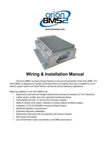
www.orionbms.comWiring & Installation ManualThe Orion BMS 2 by Ewert Energy Systems is the second generation of the Orion BMS. TheOrion BMS 2 is designed to manage and protect lithium ion battery packs and is suitable for use inelectric, plug-in hybrid, and hybrid electric vehicles as well as stationary applications.Major key additions in the Orion BMS 2 are: Significantly improved cell voltage measurement accuracy & resolution (0.1mV resolution) Lighter weight, smaller, and more optimized mechanical design Compatibility with both 12-volt and 24-volt power supplies Ability to directly drive certain contactors on select outputs (limitations apply) Integrated J1772 & CHAdeMO charging interface support Significant algorithm improvements Expanded diagnostic capabilities Significantly improved multi-unit operation with remote modules New inputs and outputs Up to 8 thermistor inputs now directly on the BMS (previously 4)
Orion BMS 2 Wiring ManualTable of ContentsSAFETY: READ THIS FIRST . 4Determining which BMS to order. 7Theory of Operation. 9Mounting . 10Physical Mounting . 10Thermal & Ventilation Information . 10Ground Lug . 11Wiring Overview . 12Connectors, Crimps, and Tooling . 14Interfacing the Load and Charger with the BMS . 15Current Limiting via the digital CANBUS (Controller Area Network) . 15Current limiting via the analog voltage outputs. . 16Current limiting via an on/off signal from the BMS. . 16Notes for specific applications . 17Main Input/Output (I/O) Connector . 18Wiring the Main I/O Connector . 21Power Supplies . 21Fusing . 21CAN interfaces . 24Wiring the CANdapter (for programming). 26On/Off Outputs . 26Multi-Purpose Outputs . 28Multi-Purpose Inputs . 32Analog 0-5V outputs . 33State of charge output (Main I/O pin 4) . 33Charge current limit (Main I/O pin 5) . 33Discharge current limit (Main I/O pin 16) . 33J1772 Interface . 34CHadeMO Interface . 35Fan controller . 36Wiring the Current Sensor / Thermistor / Remote Connector. 38Current Sensor & Thermistor Taps . 39Remote Cell Tap Modules . 42Wiring Voltage Taps . 44Voltage Tap Connector Pinouts . 462Document Revision: 1.1Last Updated: 1/9/2018
Orion BMS 2 Wiring ManualHarnesses and Cable Routing . 47Order of Cell Tap Connectors . 47Safety Disconnects and Fuse Position . 47Notes on Busbars . 51Paralleled Cells . 51Paralleled String Configuration . 54Equal currents for all cells . 55Wiring for high impedance cables and busbars . 55Skin effect issues due to AC currents . 57DC to AC Inverters and Inverter Chargers . 58Transients . 58Wiring Errors . 59Voltage tap harness lengths . 59Internal Isolation . 60Isolation Fault Detection Circuit . 60Maximum Number of Cells (Maximum System Voltage) . 62Cell Groups with fewer than 12 cells . 62Fuses on voltage tap wires . 64Verifying Cell Voltage Tap Wiring . 64Disconnect Cell Taps While Altering Battery Wiring . 65Why Orion BMS Internal Fuses Blow . 66What causes the fuses to blow? . 66Reason: Altering wiring with the BMS connected (or loose busbar) . 67Reason: Cell tap wires reversed . 69Reason: Accidental contact to cell tap . 70Reason: Transients (and shorts within the high voltage battery pack) . 70Reason: Extremely weak cell, internal cell failure (fairly rare) . 71Example Wiring . 72Battery charger without CAN: Controlling charger with enable capabilities . 72Battery charger without CAN: Controlling charger without enable capabilities . 73Over-Discharge or Under-Voltage Buzzer . 743Document Revision: 1.1Last Updated: 1/9/2018
Orion BMS 2 Wiring ManualSAFETY: READ THIS FIRSTImportant things to read first that will save you time and possibly a battery pack or BMS:This product is designed to be integrated into an application. Integration must be performed by aqualified person trained in electrical engineering and familiar with the characteristics and safetyrequirements of lithium batteries. Proper integration, selection of components, wire selection,installation, routing of cables and interconnects, and the determination of the suitability of this productfor the application are fully the responsibility of the integrator. Do not use this product if you are unsureif you possess the necessary skills to complete this integration.1) The voltage tap connectors must be DISCONNECTED from the BMS when being wired orwhen wiring is being modified for personal safety and to prevent damage. Wiring while connectedto the BMS may pose a personal safety hazard and/or fire risk since the remaining wires within thecell group can become electrically ‘hot’ due to internal protection diodes. Additionally, wiring with theBMS connected significantly increases the risk of damage to the BMS. Damage to the BMS frommis-wiring or misuse is not covered under warranty. Immediately disconnect the BMS from thebattery if the BMS is damaged.2) The BMS must have a means of controlling and shutting off any connected charger, load,source or any other means of charge and discharge. Two shutoff mechanisms should be present toturn off a charger. The charge safety signal is designed to be used as an emergency backup if a digitalCAN control or digital charge enable signal fails. If the charger does not support an analog shutoff, anAC relay can be used in series with the charger power supply. This is the last line of defense if a failureoccurs and should not be omitted. In addition to the above safety, the battery charger should beprogrammed such that it does not exceed the maximum pack voltage if a failure occurs.3) All battery packs must be protected from over-current with a suitable current limiting device such as afuse. If a fuse of safety disconnect is positioned between the first and last cell of a battery pack,it must be wired in certain locations. Read Safety Disconnects and Fuse Position for moreinformation. Failure to comply may result in catastrophic failure of the BMS from full stackpotential present across two adjacent cell taps if a fuse blows or if the safety disconnect isremoved and will not provide the required safety isolation. Read the full wiring manual beforewiring the BMS, especially the cell tap harnesses.4) Always verify voltage taps are wired correctly before plugging them into the Orion BMS. Failureto do so may result in damage to the BMS. Damage to the BMS from mis-wiring or misuse is notcovered under warranty and some incorrect wiring may pose a personal safety risk or fire risk fromenergy from the battery pack. Please see the section “Verifying the wiring” for methods of testing toensure the voltage taps are wired properly. Immediately disconnect the Orion BMS from cells if it isincorrectly wired. Leaving the Orion BMS connected to cells when incorrectly wired may drainincorrectly wired cells, even when the unit is turned off which may permanently damageconnected cells.4Document Revision: 1.1Last Updated: 1/9/2018
Orion BMS 2 Wiring Manual5) Make sure that all cells are connected to the BMS and that all current is measured by the hall effectcurrent sensor. It is the user’s responsibility to ensure the BMS is connected to all cells, to verifythe BMS has a method to limit current in and out of the pack, and to determine and supply thecorrect programming parameters (such as maximum cell voltage, minimum cell voltage,maximum temperature, etc).6) Because the Orion BMS is connected to a high voltage battery pack, hazardous voltages andhazardous energies may be present inside the unit. There are no user serviceable parts inside the unitand opening the enclosure will void the warranty. Users should never attempt to repair an Orion BMSunit. Further, a damaged unit or a unit repaired without authorization may pose additional safety risks.DAMAGED UNITS SHOULD BE IMMEDIATELY DISCONNECTED FROM ALL POWER INCLUDINGTHE BATTERY PACK AND REMOVED FROM SERVICE. NEVER CONTINUE TO USE A DAMAGEDBMS UNIT. Please contact the factory or your local distributor for repair options. Ewert Energy is notliable for damage caused by user attempted repairs or continued use of a damaged BMS unit.7) While every effort is made to ensure that the Orion BMS operates properly under all conditions, it isthe integrator’s responsibility to integrate it properly into the application such that any failure is a safefailure. For more information, please read “Failure Modes” in the operational manual. The integrator isresponsible for the determination of suitability of this product for the application, choice of all externalcomponents, including, but not limited to, wire, wiring methods, and interconnects, and complying withany regulations, standards, or codes. This product is not to be used for life support systems,medical applications, manned aircraft, weapons systems, or other applications where a failurecould cause damage to property or cause bodily harm or death.8) Paralleling separate strings of li-ion batteries together requires special considerations and a methodto isolate each string from each other. The Orion BMS may not be used with parallel stringconfigurations unless specific external safety systems are provided. Engineering work by aqualified electrical engineer is required for use with parallel strings. Generally, one Orion BMS isrequired per parallel string (in certain specific cases, it may be possible to use a single unit withreduced accuracy when isolation requirements are met). If you are using the Orion BMS in a parallelstring setup, please see our documentation about parallel strings (Note: this is different from parallelingcells inside of a single string which is very common).9) The BMS chassis must be grounded to properly bypass electrical noise to the chassis ground. Agrounding lug is provided for this purpose. Additionally, external tooth lock washers can be used onmounting screws to ensure good electrical connectivity between the chassis and the Orion BMS.Ground straps should be as short as possible using as large gauge wire as possible.10) The BMS unit must be programmed in order to function. BMS units ship from the factory with aprofile that will not allow charge or discharge for safety reasons. To program, the BMS must beconnected to a PC using the CANdapter. For more information on programming, see the softwaremanual.5Document Revision: 1.1Last Updated: 1/9/2018
Orion BMS 2 Wiring ManualALWAYS READ THE MANUAL BEFORE USE.The most up-to-date Orion BMS manuals can be downloaded at: www.orionbms.com/downloads6Document Revision: 1.1Last Updated: 1/9/2018
Orion BMS 2 Wiring ManualDetermining which BMS to orderIn order to reduce costs, the Orion BMS 2 is offered with different cell group electronics populated.Please carefully read “Wiring the BMS” to accurately determine what size BMS you require for yourapplication. Ideally, the BMS can be the same size as the actual number of cells you have or the nextsize up. However, depending on the placement of fuses, safety disconnects, and/or any high resistancebusbars / wires, it may be necessary or desirable to skip over cell tap positions on the BMS. In thosecases, the BMS may need to be sized for more cells than the pack actually has (in some cases,substantially more). For example, a battery pack that has 44 cells may require a BMS that supports 60,72, or more cells depending on where any high impedance busbars, fuses, or safety disconnects arelocated. The Orion BMS 2 is available in increments of 12 cells from 24 cells to 180 cells in a singleenclosure. A BMS unit sized for a larger number of cells can be used with a smaller number of cells (forexample, a 108 cell unit can be used with as few as 4 cells). A larger BMS unit will give more flexibilityin wiring and is recommended when the exact configuration is not known. For convenience, a wiringdiagram generator tool, which can make recommendations for a minimum BMS configuration based onthe location of disconnects and long cables, is available. The tool is available atorionbms.com/downloads.Orion BMS 2 units can be expanded by adding additional remote modules for up to a maximum of 324cells. (Note: a maximum battery voltage limitation of 800V applies, which will limit the number of cells inseries for most battery types. The BMS supports this many cells in order to allow for cell tap positions tobe skipped for fuses and safety disconnects as well as to support low voltage cells such as lithiumtitanate.)The following table shows the standard available ordering options and applies both to the main unit andremote modules. Please note that only the populated cell groups are able to sense cell voltages even ifthe connectors are present on the unit. Additional custom configurations may be available in highervolumes.72 Cell Size Enclosure108 Cell Size EnclosureBMS SizeCell Groups PopulatedBMS SizeCell Groups Populated241, 2841, 2, 3, 4, 5, 6, 7361, 2, 3961, 2, 3, 4, 5, 6, 7, 8481, 2, 3, 41081, 2, 3, 4, 5, 6, 7, 8, 948-S*1, 2 and 4, 5601, 2, 3, 4, 5721, 2, 3, 4, 5, 67Document Revision: 1.1Last Updated: 1/9/2018
180 Cell Size EnclosureBMS SizeCell Groups Populated96 –S*1, 2, 4, 5, 7, 8, 10, 111201, 2, 3, 4, 5, 6, 7, 8, 9, 101321, 2, 3, 4, 5, 6, 7, 8, 9, 10, 111441, 2, 3, 4, 5, 6, 7, 8, 9, 10, 11, 121561, 2, 3, 4, 5, 6, 7, 8, 9, 10, 11, 12, 131681, 2, 3, 4, 5, 6, 7, 8, 9, 10, 11, 12, 13, 141801, 2, 3, 4, 5, 6, 7, 8, 9, 10, 11, 12, 13, 14, 15* -S ordering options are arranged differently to provide 2.5kV isolation between cell groupsIncluded with the standard BMS Hardware CD with BMS utility software (also can be downloaded from orionbms.com) Quick Start Guide with connector pinout diagrams Safety “Read First” sheetAdditional items required to operate BMS (not included with base unit) CANdatper CAN-to-USB adapter (required for programming and diagnostics only) Crimps and connectors or pre-wired harnesses Current sensor (required for full functionality of BMS)Ordering Options Number of cells supported (see above) Current sensor options: /- 200A, 500A, 800A and 1000A Non-standard CANBUS termination options Permanently enabled or permanently disabled isolation fault detection circuit With or without support for remote modules Pre-assembled wiring harnesses or crimps and connectors are available Remote cell tap modules for split battery packs or monitoring larger numbers of cells Thermistor expansion module if more than 8 thermistors are needed per unit Displays, data loggers, cloud based remote monitoring, and PC interfaces are also available See “Purchasing Guide” for details on ordering options
Orion BMS 2 Wiring ManualTheory of OperationThe Orion BMS 2 protects and monitors a battery pack by monitoring several sensors and usingseveral outputs to control charge and discharge into the battery. The BMS measures inputs from cellvoltage taps, a hall effect current sensor, and thermistors. Using the programmed settings, the BMSthen controls the flow of current into and out of the battery pack by broadcasting charge and dischargecurrent limits (via the CANBUS or via analog reference voltages) or by simple on/off digital signalsdepending on which style is appropriate for the application. The system integrator must provide externalcontrols within the application that respect the current limits set by the BMS to protect the batteries asthe BMS does not have integrated switches. During and immediately after charging, the BMS willbalance the cells using internal shunt resistors based on the programmed settings.The Orion unit monitors each individual cell tap to insure that cell voltages are not too high or too low(in accordance with the values programmed). Using the temperatures, cell voltages, the amperagegoing in and out of the pack (provided by the current sensor), and programmed values in the batterypack profile, the BMS calculates the pack’s internal resistance, individual cells’ internal resistances, andopen cell voltages. From those calculations, the maximum charge and discharge current limits arecalculated, and adjustments are made to the pack’s calculated state of charge if necessary. Thesecalculations are also used in monitoring the health of the pack. Charge and discharge current limits areprovided on the CANBUS and can be programmed to trigger on/off digital outputs to allow or denycharging and discharging of the battery pack.The BMS also performs other functions such as cell balancing by passively removing charge from cellswhich are higher than the rest of the battery pack. The BMS will interface with J1772 AC chargingstations as well as off-board CHAdeMO chargers.Additionally, the BMS has many redundant safeties, most of which are transparent to the user. TheBMS can be programmed to monitor for a breakdown in isolation between the battery pack and BMS’sground, to detect a failure of the current sensor, and many other internal failures. Please see “failuremodes” in the operational manual for more information on failure modes.9Document Revision: 1.1Last Updated: 1/9/2018
Orion BMS 2 Wiring ManualMountingPhysical MountingThe Orion 2 BMS can be mounted in any orientation. Four to eight mounting slots are provided on themounting flanges of the BMS depending on the enclosure size of the BMS. The BMS is rated for theautomotive temperature range of -40C to 80C and is designed for use in moderately protectedlocations such as inside the passenger compartment of a vehicle. If the BMS could be exposed toharsh environments such as sprayed liquids, salt spray, or other similar conditions, it must be locatedinside a suitable protectively sealed rated enclosure. It should be noted that lithium batteriesthemselves also must typically be protected from these harsh environmental elements, and the BMS istypically located in an adjacent location.Do not install the BMS or route BMS cell tap cabling on or next to flammable materials such aswood or carpeting or in environments where explosive or combustible gases may be present.Thermal & Ventilation InformationThe Orion BMS requires unobstructed, adequate ventilation and must not be surrounded orsealed by thermal insulating material. Blocking ventilation or thermally insulating the unit maypose a fire hazard.The BMS is designed to dissipate all heat generated via convection, although a cooling fan mayoptionally be used. 108 cell size BMS units and smaller generate up to 40 watts of heat, and a 180 cellunit generates a maximum of 60 watts of heat average under normal use while balancing. Undernormal conditions, significant amounts of heat are only generated during the balancing phase ofcharge. Heat dissipation under non-balancing conditions is typically less than 3 watts. The Orion BMSis equipped to measure the internal temperature of the unit and heatsink temperature and willautomatically reduce balancing current if the temperature of the heatsink rises above 50 degreesCelsius. Even though the BMS will automatically limit balancing to maintain a specific temperaturerange, the BMS must be installed such that is has adequate ventilation to dissipate up to 40 watts for108 cell and smaller units and 60 watts for 120 cell and larger units safely without causing dangeroustemperature rise. During certain abnormal fault conditions, the unit has the potential to generate asmuch as 40 watts of heat. Ventilation must be adequate for this amount of heat even though this will notbe generated under normal use. Thermal dissipation should be considered if the BMS will be enclosedin a liquid tight enclosure.The Orion 2 BMS has a removable heatsink, which may be removed so the unit can be attached to acold plate or other heatsink. When the stock heatsink is removed, the unit must always meet theminimum heatsink requirements. Care must be taken to ensure good thermal bonds between the BMSchassis and the heatsink. Although unnecessary for most applications, forced cooling such as with fansmay be used to lower the thermal impedance. In all cases, the unit must be able to dissipate 40 wattsfor a 108 cell size and 60 watts for larger units at all times, including when the unit and cooling are off,in the event of abnormal faults. A vehicle chassis should not be treated as a heatsink.10Document Revision: 1.1Last Updated: 1/9/2018
Orion BMS 2 Wiring ManualGround LugA ground lug is provided on the outside of the enclosure. The BMS bypasses some electrical noise tothe chassis ground. The BMS MUST be grounded to a vehicle chassis or earth ground (ifstationary) for proper electrical noise rejection. In applications which do not have a groundedchassis, the chassis of the BMS must still be grounded for proper noise handling. In most of thesecases, the ground lug can be connected to the 12v - 24v power supply negative. If noise persists withthe ground lug connected to the negative on the 12v - 24v power supply, it may be necessary to identifythe noise source and evaluate a different grounding path.The voltage of the BMS chassis with respect to the voltage of the 12v – 24v ground may neverexceed 50V. When in doubt, ensure that the BMS chassis is grounded to the 12v – 24v power supplynegative.11Document Revision: 1.1Last Updated: 1/9/2018
Orion BMS 2 Wiring ManualWiring OverviewOverview of system connectionsConnector locations on the 72 and 108 cell Orion BMS 2 units12Document Revision: 1.1Last Updated: 1/9/2018
Orion BMS 2 Wiring ManualConnector locations on the 180 cell Orion BMS 2 unit13Document Revision: 1.1Last Updated: 1/9/2018
Orion BMS 2 Wiring ManualConnectors, Crimps, and ToolingFor ease of installation, pre-crimped harnesses are available from Ewert Energy, and they are recommended for prototyping and small runs. For larger runs, however, it is usually beneficial to have the harnesses custom manufactured for the exact specifications needed as this reduces waste and assemblytime. Contact Ewert Energy Systems for recommendations on cable houses for custom har
The Orion BMS 2 is available in increments of 12 cells from 24 cells to 180 cells in a single enclosure. A BMS unit sized for a larger number of cells can be used with a smaller number of cells (for example, a 108 cell unit can be used with as few as 4 cells). A larger BMS unit will give more flexibility in wiring and is recommended when the exact configuration is not known. For convenience, a .
