Transcription
Design Standards No. 13Embankment DamsChapter 2: Embankment DesignPhase 4 (Final)U.S. Department of the InteriorBureau of ReclamationDecember 2012
Mission StatementsThe U.S. Department of the Interior protects America's naturalresources and heritage, honors our cultures and tribal communities,and supplies the energy to power our future.The mission of the Bureau of Reclamation is to manage, develop, andprotect water and related resources in an environmentally andeconomically sound manner in the interest of the American public.
Design Standards Signature SheetDesign Standards No. 13Embankment DamsDS-13(2)-10: Phase 4 (Final)December 2012Chapter 2: Embankment Design
Chapter Signature SheetBureau of ReclamationTechnical Service CenterDesign Standards No. 13Embankment DamsChapter 2: Embankment DesignDS-13(2)-10:1 Phase 4 (Final)Chapter 2 – Embankment Design is an existing chapter (last revised June 1992)within Design Standards No. 13 and was revised as follows: Minor revisions to reflect current terminology Minor revisions to reflect latest state-of-practice Added photographs and drawings1DS-13(2)-10 refers to Design Standard No. 13, chapter 2, revision 10.
Prepared by:,Atkog.William . Engemoen, P.E. Civil En neer, Geotechnical Services DivisionDatePeer Review:vo l —Allen H. Kiene, P.E.Civil Engineer, Geotechnical Engineering Group 2DateSecurity Review:Robert L. Dewey, P.E.Civil Engineer, Geotechnical Engineering Group 3DateReco mended for Technical Approval:V2/Thomas McDaniel, P.E.Geotechnical Engineer, Geotechnical Engineering Group 2teSubmitted:Kart Knight, P.E.Chief, Geotechnical Services DivisionApproved:512 0/I 4Lowell Pimley, P.E.Director, Technical Service CenterDesign Standards No. 13, Chapter 2Date
ContentsPage2.12.22.3Introduction. 2-12.1.1Purpose. 2-12.1.2Scope. 2-12.1.3Deviations from Standard . 2-12.1.4Revisions of Standard . 2-1Applicability . 2-12.1.5Earthfill Dams . 2-22.2.1Origin and Development . 2-22.2.2General Comments on Earthfill Dams . 2-32.2.2.1Selection and Types of Earthfill Dams . 2-32.2.2.2Design Data. 2-72.2.2.3Criteria for Design . 2-8General Construction Methods . 2-102.2.2.42.2.3Foundation Design for Earthfill Dams. 2-102.2.3.1General. 2-102.2.3.2Rock Foundations . 2-112.2.3.3Sand and Gravel Foundations . 2-15Silt and Clay Foundations . 2-192.2.3.42.2.4Embankment Design for Earthfill Dams. 2-222.2.4.1Static Stability. 2-222.2.4.2Seepage and Leakage throughEmbankments . 2-23Utilization of Materials from Required2.2.4.3Excavation. 2-292.2.4.4Zoning . 2-322.2.4.5Seismic Design. 2-372.2.4.6Security Considerations . 2-37Embankment Details for Earthfill Dams. 2-382.2.52.2.5.1Crest Details. 2-382.2.5.2Freeboard . 2-422.2.5.3Upstream Slope Protection . 2-44Downstream Slope Protection. 2-482.2.5.42.2.5.5Surface Drainage. 2-50Flared Slopes at Abutments . 2-512.2.5.62.2.5.7Typical Maximum Sections . 2-52Rockfill Dams . 2-522.3.1Origin and Usage . 2-522.3.2Definition and Types of Rockfill Dams . 2-532.3.3Impervious Elements Other than Clay Cores. 2-562.3.4Foundation Design for Rockfill Dams . 2-572.3.4.1Foundation Requirements and Treatment . 2-572.3.4.2Membrane Cutoffs . 2-58DS-13(2)-10December 20122-i
Contents (continued)Page2.3.52.42.5Embankment Design for Rockfill Dams . 2-612.3.5.1Selection of Rock Materials. 2-612.3.5.2Embankment Sections for Rockfill Dams. 2-662.3.5.3Stability . 2-702.3.5.4Placement of Rockfill Materials . 2-702.3.5.5Compaction . 2-712.3.6Membrane Design for Rockfill Dams . 2-722.3.6.1Impervious Core. 2-722.3.6.2Reinforced Concrete . 2-732.3.6.3Asphaltic Concrete. 2-76Steel Facings . 2-822.3.6.42.3.6.5Timber Planking. 2-842.3.6.6Geomembranes . 2-84Evaluating and Modifying Existing Embankment Dams . 2-84References. iiPageEffects of drainage . 2-5Types of earthfill dams. . 2-9Examples of filters around penetrating conduits: (a) typicalfilter addition around a conduit near the centerline of adam, and (b) typical filter addition around a conduitnear the downstream toe of a dam . 2-27Recommended design and compaction details forpenetrating conduit. 2-29Use of random fill materials within an embankment. . 2-31Example materials distribution chart. . 2-33Crest and camber details - Jordanelle Dam, Utah. . 2-40Examples of crest details at maximum camber. 2-43Riprap on upstream slope of Horsetooth Dam, Colorado . 2-45Soil-cement slope protection at Choke Canyon Dam, Texas. . 2-46Placement of soil-cement slope protection, StarvationDam, Utah. . 2-47Placement of soil-cement on the interior embankmentslopes of Warren H. Brock Reservoir, California,using the plating method of placement. . 2-48Cobble slope protection on downstream slope ofJordanelle Dam, Utah. 2-49DS-13(2)-10December 2012
Figures egetated slope protection on downstream slope ofScoggins Dam, Oregon. . 2-49Contour ditch at Belle Fourche Dam, South Dakota. . 2-50Typical sections of a contour ditch and an open drain. 2-51Types of rockfill dams. . 2-54Effect of upstream membrane on embankment resistanceto sliding. 2-56Detail of asphaltic concrete membrane at cutoff wall . 2-58Details of (a) concrete cutoff wall, and (b) doweledcutoff slab for a concrete membrane. . 2-59Detail of steel plate membrane at cutoff wall. . 2-60Rockfill on the downstream slope of New Melones Dam,California. . 2-62Grain size distribution for modeled rockfill materials. . 2-64Effect of maximum particle size on the angle ofinternal friction. 2-65Shearing resistance of rockfill from large triaxial tests . 2-66Placement of sand filter and gravel drain material atSpring Canyon Dam, Colorado. . 2-73Placing concrete using slip forms on the upstream slopeof New Exchequer Dam, California. 2-76Completed rockfill embankment at Upper Blue River Dam,Colorado, during membrane placement . 2-77Placing asphaltic concrete on the upstream slopeof Montgomery Dam, Colorado. 2-78Foundation cutoff used at Montgomery Dam, Colorado. . 2-80Completed asphaltic concrete facing at Upper BlueRiver Dam, Colorado . 2-822007 photograph of upstream slope of El Vado Dam,New Mexico. . 2-83December 20122-iii
Chapter 2Embankment Design2.1Introduction2.1.1PurposeThe purpose of this chapter is to give basic guidance for the design ofembankment dams within the Bureau of Reclamation (Reclamation).2.1.2ScopeDesign procedures and concepts, with direction to appropriate chapters withinDesign Standard No. 13 - Embankment Dams for specific methods or analyses,are presented for both earth and rockfill dams. These guidelines are limited todesign procedures for rolled-fill type construction. This type of placement is nowused almost exclusively in the construction of embankment dams, to the exclusionof semi-hydraulic and hydraulic fills and dumped rockfills. The focus of thischapter is on the design of new embankment dams, although Section 2.4,“Evaluating and Modifying Existing Embankment Dams,” discusses applicabilityto existing embankment dams.2.1.3Deviations from StandardDesign and analysis of embankment dams within Reclamation should adhere toconcepts and methodologies presented in this design standard. Rationale fordeviation from the standard should be presented in technical documentation forthe dam and should be approved by appropriate line supervisors and managers.2.1.4Revisions of StandardThis standard will be revised periodically as its use or the state of practicesuggests. Comments and/or suggested revisions should be sent to the Bureau ofReclamation, Technical Service Center, Attn: 86-68300, Denver, CO 80225.2.1.5ApplicabilityThese standards apply to all embankment dams (earth or rockfill dams) designedby the Reclamation.DS-13(2)-10December 20122-1
Design Standards No. 13: Embankment Dams2.2Earthfill Dams2.2.1Origin and DevelopmentEmbankments for the storage of water for irrigation, as attested to both byhistorians and archaeologists, have been used since the early days of civilization.Some of the structures built in antiquity were of considerable size. One earthfilldam that was 11 miles long, 70 feet high, and contained approximately 17 millioncubic yards of embankment was completed in Ceylon (Sri Lanka) in the year504 B.C. Today, as in the past, the earthfill dam continues to be the mostcommon type of dam, principally because its construction involves usingmaterials obtained from required excavation and locally available earth and rockmaterials obtained from borrow areas located near the damsite.Until modern times, embankment dams were designed based on experience andprecedence (empirical means). However, the engineering literature is replete withaccounts of failures [1, 2, 3] of embankment dams. These failures produced therealization that totally empirical means must be replaced, or at leastsupplemented, by analytical engineering procedures in both design andconstruction. One of the first to suggest that the slopes for earthfill dams beselected based on analytical procedures was Bassell in 1907 [4]. However, littleprogress was made on the development of rational design procedures until the1930s. The rapid advancement of the science of soil mechanics and geotechnicalengineering since then has resulted in the development of greatly improvedprocedures for the design of embankment dams.These procedures include: Thorough preconstruction investigations of foundation conditions andmaterials for construction Application of engineering analyses and experiences to design Carefully planned and controlled methods of construction Carefully planned and designed instrumentation and monitoring systemsThreaded throughout the Plan, Design, Construct, Operate, and Maintain processfor an embankment dam is the philosophy that design is not complete until thedam is accomplishing its purpose and has proven itself safe through several cyclesof operation.As a result of analytical engineering procedures, a few embankment dams havebeen constructed to heights greater than 1,000 feet above their foundations,2-2DS-13(2)-10December 2012
Chapter 2: Embankment Designand hundreds of large rolled earthfill dams have been constructed in the past50 years with a good success record.2.2.2General Comments on Earthfill Dams2.2.2.1 Selection and Types of Earthfill DamsThe selection of type of dam is discussed in Design Standard No. 13, Chapter 1,“General Design Standards.” When this procedure leads to the selection of anearthfill dam, a further decision must be made as to the type of earthfill dam:diaphragm, homogeneous, or zoned. An earthfill dam is designed considering thetopographic and foundation conditions at the site and using available constructionmaterials.2.2.2.1.1 Diaphragm EmbankmentsIn this type of section, the bulk of the embankment is constructed of perviousmaterial (sand, gravel, or rock), and a thin diaphragm of impermeable material isprovided to form the water barrier. The position of this impervious diaphragmmay vary from a membrane placed on the upstream face to a centrally locateddiaphragm. The diaphragm or membrane may consist of asphaltic concrete,reinforced concrete, metal, compacted earthfill, or geomembrane. If compactedearthfill is used, the diaphragm is typically called a thin core. Internal diaphragmshave the disadvantage of not being readily available for inspection or emergencyrepair if they are ruptured due to a material flaw or settlement of the dam or itsfoundation.Examples of various materials that have been used to provide a diaphragm waterbarrier include:1. Geomembrane on upstream face - Warren H. Brock Reservoir, California2. Internal geomembrane – Reach 11 Dikes, Arizona3. Concrete cutoff wall - Tieton Dam, Washington4. Other cutoff walls such as secant pile (Lake Tahoe Dam) and sheet pile(Fourth Creek Dam, U.S. Bureau of Indian Affairs [BIA])5. Plastic concrete cutoff wall – Meeks Cabin Dam, Wyoming6. Fiber reinforced polymer – Coquille Dams (BIA), Oregon7. Cement bentonite cutoff wall – Diamond Creek Dike, Wyoming8. Steel sheetpile cutoff wall – Lake Wolford Dam, CaliforniaDS-13(2)-10December 20122-3
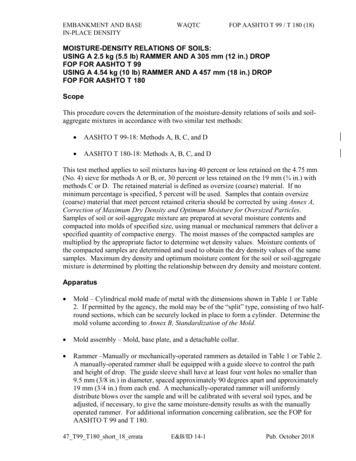
Design Standards No. 13: Embankment Dams9. Steel plates on upstream face – El Vado Dam, New Mexico10. Concrete-faced rockfill – Exchequer Dam, California11. Asphaltic concrete-faced embankment – Montgomery Dam, ColoradoIf the bulk of material comprising the diaphragm-type dam is rock, the damis classified as a rockfill dam. The design of rockfill dams is discussed inSection 2.3, “Rockfill Dams.”2.2.2.1.2Homogeneous EmbankmentsA significant number of embankment dams have been designed and constructed,and the majority of these dams may well be homogenous embankments.Similarly, many of Reclamation’s dams are homogeneous. In general,embankment dam design philosophy has changed from minimizing seepage (witha wide homogeneous cross section) to controlling seepage by incorporating filterand drainage elements. As such, purely homogeneous embankments are notrecommended when designing/constructing new dams, especially high hazarddams.A purely homogeneous type of dam is composed of a single kind of material(except for the slope protection). The material comprising the dam must besufficiently impervious to provide an adequate water barrier. Soils meeting thisrequirement generally have shear strengths such that the slopes of the dam mustbe relatively flat for stability. To avoid sloughing, the upstream slope must be flatenough to maintain stability if rapid drawdown of the reservoir after long-termstorage is anticipated. The downstream slope must be flat enough to provideembankment stability when the reservoir is filled and the bulk of the dambecomes saturated. For a completely homogeneous section on an imperviousfoundation, seepage will emerge on the downstream slope regardless of theembankment slope and the permeability of the embankment material if thereservoir level is maintained for a long period of time. Under such conditions,the downstream slope will eventually be affected by seepage to a theoreticalheight of roughly one-third the depth of the reservoir pool, as shown onfigure 2.2.2.1.2-1(A). However, in practice, whether or not seepage exits on thedownstream face depends on the permeability of the foundation and embankmentmaterials, as well as reservoir operations.Although formerly very common, the purely homogeneous section-type dam hasbeen replaced by a modified homogeneous section in which internally placedpervious materials control seepage and the saturation (phreatic surface) within thedam, thus permitting steeper slopes. The modification of the homogeneous typeof section to include drainage features provides a greatly improved design. Themodified homogeneous type of dam is applicable in localities where readilyavailable soils show little variation in permeability, and soils of contrastingpermeabilities are available only in minor amounts or at considerably greater cost.2-4DS-13(2)-10December 2012
Chapter 2: Embankment DesignFigure 2.2.2.1.2-1 shows the effect of providing drainage at the downstream toe ina modified homogeneous dam.Figure 2.2.2.1.2-1. Effects of drainage.DS-13(2)-10December 20122-5
Design Standards No. 13: Embankment DamsTheoretically, rock toes or drainage blankets, as shown on figures 2.2.2.1.2-1(B)and 2.2.2.1.2-1(C) will lower the phreatic surface. However, these features arenot designed to intercept seepage or leakage (and possible internal erosion) thatcan progress along cracks that may form after fill placement or to intercept morepervious, or loosely compacted, or poorly bonded lifts that might inadvertentlyoccur during construction. Fundamentally, this lack of an internal filter/drainagefeature to prevent internal erosion is probably the most significant deficiency withthis type of dam. Another consideration is the fact that embankments with soilsplaced in layers are inherently much more pervious horizontally than vertically,causing a tendency for seepage to advance more rapidly and further horizontally.That ratio is difficult to predict, which makes it difficult to predict where seepagewill exit on the slope. Figure 2.2.2.1.2-1(D) shows a chimney filter/drain that isdesigned to intercept these flows and mitigate potential deficiencies. In recentyears, use of the chimney filter/drain has become standard practice in allhomogeneous type dams and should be included in all Reclamation dams unlessvery specific circumstances preclude the need. The drainage and filter layersmust be designed to meet filter requirements with surrounding fill or foundationmaterials.Another method of improving and collecting drainage is the installation of pipedrains. These are normally used in conjunction with the horizontal drainageblanket or toe drain. Pipe drains should only be located in areas where they canbe inspected, maintained, and accessed for repair without affecting embankmentslope stability.A homogeneous section should never be used if the available materials aredispersive and erodible, such as silts and fine sands, or if they are subject tomoderate to severe cracking because of desiccation or high seismicity. Soilsshould always be tested for these characteristics.2.2.2.1.3Zoned EmbankmentsCompared to a modified homogeneous dam, zoned dams (such as Ridgway,McPhee, Jordanelle, and New Waddell Dams) are usually constructed in areaswhere several material types are available, such as clays, silts, sands, gravels, androck. Zoned embankments take advantage of the availability of various materialsby placing different materials in various zones so that their best properties areused most beneficially, and their poor properties are mitigated. A zoned earthfilldam typically has a central impervious core flanked by upstream transition zones,downstream filters and drains, and then outer zones or shells composed ofgravelfill, rockfill, or random fill, which are considerably stronger than the core.Depending on the gradation of available materials, transition zones may not benecessary. The shells support and protect the impervious core, transition zones,filters, and drains; the upstream pervious zone provides strength for stabilityagainst rapid drawdown; and the downstream zone provides strength to buttressthe core and filters so that steeper (more economical) slopes can be used. Theupstream transition zone, if necessary because of a very pervious shell, providesprotection against internal erosion or washout of the core during rapid drawdown,2-6DS-13(2)-10December 2012
Chapter 2: Embankment Designand protection against cracking of the core. The downstream filters and drainscontrol seepage and leakage and prevent sediment transport through any cracks inthe central impervious core. The dam is considered to be a thin core dam if theimpervious zone has a horizontal width less than 10 feet at any elevation belownormal reservoir level, or if it has a ratio of hydraulic head to horizontal width of2.0 or greater. This ratio should not be greater than 4 without special analysesand provisions to control seepage and high seepage exit gradients through theimpervious core and its foundation.The shells and transition zones preferably consist of sand, gravel, cobbles, orrock, or mixtures of these materials. The impervious core is constructed frommore impervious fine-grained soils such as silts, clays, sandy silts, sandy clays,and gravelly clays, or mixtures thereof. Although not as desirable, fat clays andgravelly silts have also been used for the impervious zone. Gravelly clays, sandyclays, and lean clays are the most desirable impervious materials. The filters anddrains are generally processed from available sands and gravels and must meetfilter criteria with surrounding materials (see Design Standard No. 13, Chapter 5,“Protective Filters”). Chapters 4, 5, 7, 8, and 9 of Design Standard No. 13 discussthe design of the various zones.A dam with an impervious core of moderate width composed of strong materialand with pervious outer shells may have relatively steep outer slopes, limited onlyby the strength of the foundation material, the stability of the embankment itself,and maintenance considerations. Conditions that tend to increase stability maycontrol the choice of a design cross section even if a longer haul is necessary toobtain such embankment materials.If a variety of soils are readily available, a zoned embankment will usually bechosen because it is generally superior for both stability and seepage performance.Zoned dams (as discussed later) also afford better ability to use material in theembankment section from required excavation. Materials that are closest to thedam and require the least processing should be used for the best economy.2.2.2.2 Design DataThe data required from investigation of foundations and sources of constructionmaterials for the design of an embankment dam are discussed in Design StandardNo. 13, Chapter 12, “Foundation and Earth Materials Investigation”; the EarthManual [5 and 6], and the Engineering Geology Field Manual [7 and 8]. Theextent of required data and methods of obtaining the data will be governed by thenature of the project and the purpose of the design (i.e., whether the design isintended as a basis for a cost estimate to determine project feasibility, forconstruction, or some other purpose). The extent of investigations of foundationsand sources of construction material will also be governed by the complexity ofthe site conditions.DS-13(2)-10December 20122-7
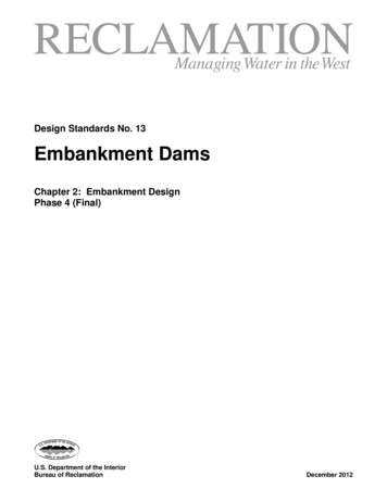
Design Standards No. 13: Embankment Dams2.2.2.3 Criteria for DesignThe basic objective of design is to produce a satisfactory functional structure at aminimum total cost. Consideration must be given to maintenance requirements sothat any cost savings achieved by the selection or elimination of certain designfeatures will not result in excessive maintenance costs. Maintenance costs varywith the provisions of upstream and downstream slope protection, availability ofmaterials for future maintenance and repair, drainage features, and the type ofappurtenant structures and mechanical equipment.To achieve minimum cost, the dam should be designed for maximum use ofthe most economical materials available, including materials which mustbe excavated for the dam’s foundation and for appurtenant structures.Figure 2.2.2.3-1 illustrates the types of earthfill dams.An earthfill dam must be safe and stable during all phases of construction andoperation of the reservoir. This requires defensive design measures and usuallysome redundancy because of the potential hazard to the public from most dams.For example, control of seepage and leakage requires the use of an imperviouszone of some kind within the embankment and within cutoff trenches excavatedthrough pervious zones within the foundation. Additionally, filters and drainagefeatures are required to control seepage or leakage that may find its way throughimpervious zones, and to protect against internal erosion. In earthquake regions,the filters and drains are designed to increased widths to provide for the potentialoccurrence of cracking or displacement of the embankment during an earthquake.Toe drains are added to provide seepage control and, in pervious foundations,relief wells are sometimes used to control seepage or reduce pore pressures deeperin the foundation.An earthfill dam designed to meet the requirements listed in Design StandardNo. 13, Chapter 1, “General Design Standards,” will safely fulfill projectobjectives provided that proper construction methods and control are achieved.The design procedures and guidelines necessary to meet the requirements of thesecriteria are provided in various other chapters of Design Standard No. 13.Embankment Dams.2-8DS-13(2)-10December 2012
Chapter 2: Embankment DesignFigure 2.2.2.3-1. Types of earthfill dams.DS-13(2)-10December 20122-9
Design Standards No. 13: Embankment Dams2.2.2.4 General Construction MethodsThe designer assumes that certain construction methods are used, such asplacement in lifts, and that equipment such as rollers are used for compaction ofthe embankment. The success of the design depends on implementation of theseassumptions; therefore, it is necessary to monitor construction to ensure thatappropriate equipment and construction methods are used. These considerationsare discussed in detail in Design Standard No. 13, Chapter 10, “EmbankmentConstruction.”2.2.3Foundation Design for Earthfill Dams2.2.3.1 GeneralThe term “foundation,” as used herein, includes both the valley floor and theabutments upon which the embankment will be built. A foundation for anearthfill dam has two essential requirements: (1) it must provide stable supportfor the embankment under all conditions of saturation and loading, and (2) it mustprovide sufficient resistance to seepage to prevent internal erosion or excessiveloss of water.Although the foundation is not actually designed, certain provisions for treatmentof the foundation are provided in designs to ensure that the essential requirementswill be met. Such measures may include excavation of unsatisfactory materials,foundation grouting, material densification, use of filters, and surface treatmentmeasures such as shaping, slush grouting, and dental concrete. Each foundationpresents its own separate and distinct problems that require corresponding specialtreatment and preparation. Various methods for stabilizing weak foundations,reducing seepage in permeable foundations, shaping to reduce differentialsettlement to acceptable levels, and types and locations of devices for interceptingunderseepage must be adapted to local conditions.Surveys and compiled statistics vary [1, 2, 9, 10], but it appears that between10 and 20 percent of embankment dam failures, and close to 50 percent ofincidents at embankment dams, can be attributed to the foundation. Thesestatistics indicate the importance of understanding the foundation. Thefoundation must be adequately explored to characterize its properties. The datafrom the exploration program is interpreted by engineering geologists and mustreveal subsurface conditions to permit safe and economical design of foundationtreatment. The exploration program s
1930s. The rapid advancement of the science of soil mechanics and geotechnical engineering since then has resulted in the development of greatly improved procedures for the design of embankment dams. These procedures include: Thorough preconstruction investigations of foundation conditions and materials for construction