Transcription
Spring 2012EECS810 – Principles of Software EngineeringBharath PadmanabhanUNIFIED MODELING LANGUAGE(UML) OVERVIEWUnified Modeling Language (UML) is a graphical language for visualizing, specifying, constructing, anddocumenting the artifacts of a software-intensive system. It offers a standard way to write a system’sblueprints, including conceptual things such as business processes and system functions as well as concretethings such as programming language statements, database schemas, and reusable software components.
Table of ContentsIntroduction . 1Modeling . 1Static (or structural) view. 1Dynamic (or behavioral) view . 1Diagrams Overview . 1Structure Diagrams . 21.Class Diagram . 22.Component Diagram . 23.Composite Structure Diagram. 24.Deployment Diagram . 35.Object Diagram . 36.Package Diagram . 47.Profile Diagram . 4Behavior Diagrams . 51.Activity Diagram . 52.State Machine Diagram. 63.Use Case Diagram . 6Interaction Diagrams . 71.Communication Diagram . 72.Interaction Overview Diagram . 83.Sequence Diagram . 94.Timing Diagram . 9References . 10
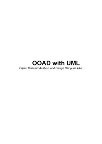
Unified Modeling Language (UML) OverviewIntroductionUnified Modeling Language (UML) is a standardized general-purpose modeling language in the field ofobject-oriented software engineering. UML includes a set of graphic notation techniques to createvisual models of object-oriented software systems. UML combines techniques from data modeling,business modeling, object modeling, and component modeling and can be used throughout thesoftware development life-cycle and across different implementation technologies.ModelingThere is a difference between a UML model and the set of diagrams of a system. A diagram is a partialgraphic representation of a system’s model. The model also contains documentation that drives themodel elements and diagrams (such as written use cases).UML diagrams represent two different views of a system model:Static (or structural) viewThis view emphasizes the static structure of the system using objects, attributes, operations, andrelationships. Ex: Class diagram, Composite Structure diagram.Dynamic (or behavioral) viewThis view emphasizes the dynamic behavior of the system by showing collaborations among objects andchanges to the internal states of objects. Ex: Sequence diagram, Activity diagram, State Machinediagram.Diagrams OverviewUML 2.2 has 14 types of diagrams divided into multiple categories as shown in the figure below.Bharath Padmanabhan, 2/21/2012Page 1
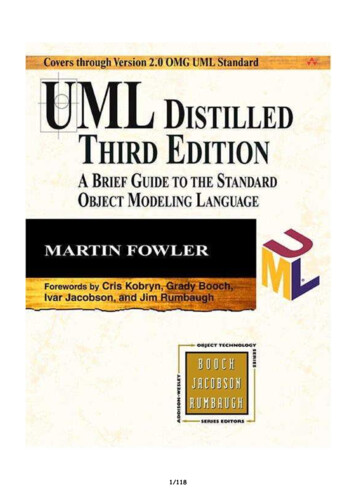
Unified Modeling Language (UML) OverviewStructure DiagramsThese diagrams emphasize the things that must be present in the system being modeled. Since theyrepresent the structure, they are used extensively in documenting the software architecture of softwaresystems.1. Class DiagramDescribes the structure of a system by showing the system’s classes, their attributes, and therelationships among the classes.2. Component DiagramDescribes how a software system is split-up into components and shows the dependencies amongthese components.3. Composite Structure DiagramDescribes the internal structure of a class and the collaborations that this structure makes possible.Bharath Padmanabhan, 2/21/2012Page 2
Unified Modeling Language (UML) Overview4. Deployment DiagramDescribes the hardware used in system implementations and the execution environments andartifacts deployed on the hardware.5. Object DiagramShows a complete or partial view of the structure of an example modeled system at a specific time.Bharath Padmanabhan, 2/21/2012Page 3
Unified Modeling Language (UML) Overview6. Package DiagramDescribes how a system is split-up into logical groupings by showing the dependencies among thesegroupings.7. Profile DiagramOperates at the metamodel level to show stereotypes as classes with the stereotype stereotype, and profiles as packages with the profile stereotype. The extension relation (solidline with closed, filled arrowhead) indicates what metamodel element a given stereotype isextending.Bharath Padmanabhan, 2/21/2012Page 4
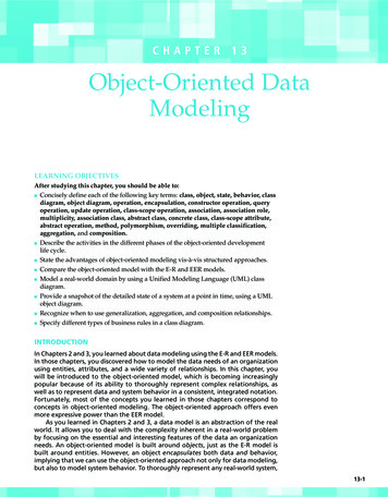
Unified Modeling Language (UML) OverviewBehavior DiagramsThese diagrams emphasize what must happen in the system being modeled. Since they illustrate thebehavior of a system, they are used extensively to describe the functionality of software systems.1. Activity DiagramDescribes the business and operational step-by-step workflows of components in a system. Anactivity diagram shows the overall flow of control.Bharath Padmanabhan, 2/21/2012Page 5
Unified Modeling Language (UML) Overview2. State Machine DiagramDescribes the states and state transitions of the system.3. Use Case DiagramDescribes the functionality provided by a system in terms of actors, their goals represented as usecases, and any dependencies among those use cases.Bharath Padmanabhan, 2/21/2012Page 6
Unified Modeling Language (UML) OverviewInteraction DiagramsThese diagrams are a subset of behavior diagrams, emphasizing the flow of control and data among thethings in the system being modeled.1. Communication DiagramShows the interactions between objects or parts in terms of sequenced messages. They represent acombination of information taken from Class, Sequence, and Use Case Diagrams describing both thestatic structure and dynamic behavior of a system.Bharath Padmanabhan, 2/21/2012Page 7
Unified Modeling Language (UML) Overview2. Interaction Overview DiagramProvides an overview in which the nodes represent communication diagrams. They are activitydiagrams in which every node, instead of being an activity, is a rectangular frame containing aninteraction diagram (i.e., a communication, interaction overview, sequence, or UML timingdiagram).Bharath Padmanabhan, 2/21/2012Page 8
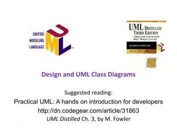
Unified Modeling Language (UML) Overview3. Sequence DiagramShows how objects communicate with each other in terms of a sequence of messages. Alsoindicates the lifespans of objects relative to those messages.4. Timing DiagramA specific type of interaction diagram where the focus is on timing constraints. Timing diagramsmodel sequence of events and their effects on states and property values. Time flows along ahorizontal axis from left to right. They can be used to show method execution profiling orconcurrency scenarios.Bharath Padmanabhan, 2/21/2012Page 9
Unified Modeling Language (UML) OverviewReferencesUnified Modeling Languagehttp://en.wikipedia.org/wiki/Unified Modeling LanguageUML basics: The component library/dec04/bell/Practical UML: A Hands-On Introduction for O – UML Behavior o-uml-behavior-diagrams.htmlUML 2 Tutorialhttp://www.sparxsystems.com/resources/uml2 tutorial/Bharath Padmanabhan, 2/21/2012Page 10
Unified Modeling Language (UML) Overview Bharath Padmanabhan, 2/21/2012 Page 4 6. Package Diagram Describes how a system is split-up into logical groupings by showing the dependencies among these