Transcription
VEL TECH HIGH TECH Dr. RANGARAJAN Dr. SAKUNTHALA ENGINEERING COLLEGEUNIT 1UML DIAGRAMSIntroduction to OOAD – Unified Process - UML diagrams – Use Case – Class Diagrams–Interaction Diagrams – State Diagrams – Activity Diagrams – Package, component andDeployment Diagrams.INTRODUCTION TO OOADANALYSISAnalysis is a creative activity or an investigation of the problem and requirements.Eg. To develop a Banking systemAnalysis: How the system will be used?Who are the users?What are its functionalities?DESIGNDesign is to provide a conceptual solution that satisfies the requirements of a givenproblem.Eg. For a Book Bank SystemDesign: Bank(Bank name, No of Members, Address)Student(Membership No,Name,Book Name, Amount Paid)OBJECT ORIENTED ANALYSIS (OOA)Object Oriented Analysis is a process of identifying classes that plays an important role inachieving system goals and requirements.Eg. For a Book Bank System, Classes or Objects identified are Book-details,Student-details, Membership-Details.OBJECT ORIENTED DESIGN (OOD)Object Oriented Design is to design the classes identified during analysis phase and to providethe relationship that exists between them that satisfies the requirements.Eg. Book Bank SystemClass name Book-Bank (Book-Name, No-of-Members, Address)Student (Name, Membership No, Amount-Paid)OBJECT ORIENTED ANALYSIS AND DESIGN (OOAD) OOAD is a Software Engineering approach that models an application by a set ofSoftware Development Activities.YEAR/SEM: III/VCS6502-OOADPage 1
VEL TECH HIGH TECH Dr. RANGARAJAN Dr. SAKUNTHALA ENGINEERING COLLEGE OOAD emphasis on identifying, describing and defining the software objects and showshow they collaborate with one another to fulfill the requirements by applying the objectoriented paradigm and visual modeling throughout the development life cycles.UNIFIED PROCESS (UP)The Unified Process has emerged as a popular iterative software development process forbuilding object oriented systems. The Unified Process (UP) combines commonly accepted bestpractices, such as an iterative lifecycle and risk-driven development, into a cohesive and welldocumented description. The best-known and extensively documented refinement of theUnified Process is the Rational Unified Process (RUP).Reasons to use UP UP is an iterative process UP practices provide an example structure to talk about how to do, and how to learnOOA/D.Best Practices and Key Concepts in UP Tackle high-risk and high-value issues in early iterations Engage users continuously for evaluation, feedback, and requirements Build a cohesive, core architecture in early iterations Apply use cases Provides visual modeling using UML Practice change request and configuration management.UP PHASESThere are 4 phases in Unified Process,1. Inception2. Elaboration3. Construction4. TransitionINCEPTIONInception is the initial stage of the project. Inception is not a requirements phase but it is afeasibility phase where complete investigation takes place to support a decision to continue orstop .It deals with Approximate vision Business case Scope Vague estimatesYEAR/SEM: III/VCS6502-OOADPage 2
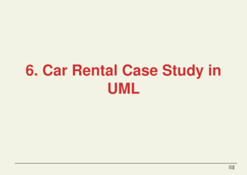
VEL TECH HIGH TECH Dr. RANGARAJAN Dr. SAKUNTHALA ENGINEERING COLLEGEELABORATIONIn Elaboration phase the project team is expected to capture a healthy majority of the systemrequirements It deals with Refined vision, Iterative implementation of the core architecture, Resolution of high risks, Identification of most requirements and scope, Realistic estimates.CONSTRUCTIONConstruction phase encompasses on iterative implementation of the remaining lower risk andeasier elements, and preparation for deployment.TRANSITIONTransition phase focus on releasing the final product to the customers for usability.Fig: Phases of UPUP DISCIPLINES UP describes work activities such as writing a use case within disciplines a set ofactivities and related artifacts in one subject area within requirement analysis.Artifact-any work such as code, web graphics, database schema, text documents,diagrams, models etc.YEAR/SEM: III/VCS6502-OOADPage 3
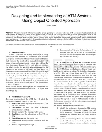
VEL TECH HIGH TECH Dr. RANGARAJAN Dr. SAKUNTHALA ENGINEERING COLLEGESeveral UP Disciplines1. Business Modeling- Domain Model artifact to visualize concepts in theapplication domain.2. Requirements- use case model and specification artifacts to capture functionaland non-functional requirements.3. Design- All aspects of design, including overall architecture, objects, databases,networking.Fig: Sample UP DisciplinesUML DIAGRAMSUML: Unified Modeling Language(UML) is a standard notation for the modeling of real-worldobjects as s first step in developing an object oriented design methodology. UML is a Visual language for specifying,constructing and documenting the artifacts of asystem. The Various UML diagrams are as follows,i. Use Case Diagramii. Class DiagramYEAR/SEM: III/VCS6502-OOADPage 4
VEL TECH HIGH TECH Dr. RANGARAJAN Dr. SAKUNTHALA ENGINEERING COLLEGEiii. Interaction Diagram Sequence Diagram Collaboration Diagram or Communication Diagramiv. State Diagramv. Activity Diagramvi. Package Diagramvii. Component Diagramviii. Deployment DiagramThree ways to apply UML:1. UML as sketch:Informal and incomplete diagrams created to explore difficult parts of the problem.2. UML as blueprint:Detailed design diagram used for better understanding of code.3. UML as programming language:Complete executable specification of a software system in UML.Three perspectives to apply UML:1. Conceptual perspective: Diagrams describe the things of real world.2. Specification perspective: Diagrams describe software abstractions or components withspecifications and interfaces.3. Implementation perspective: Diagrams describe software implementation in aparticular technology.USE CASE DIAGRAMUse case diagrams are used to describe a set of actions (use cases) that some system or systemsshould or can perform in collaboration with one or more external users of the system (actors).Each use case should provide some observable and valuable result to the actors or otherstakeholders of the system.Purpose:1. Used to gather requirements of a system2. Used to get an outside view of a system3. Identify external and internal factors influencing the system4. Show the interaction among the requirements through actors.Uses:1. Requirement analysis and high level design2. Model the context of a system3. Reverse engineering4. Forward engineeringYEAR/SEM: III/VCS6502-OOADPage 5
VEL TECH HIGH TECH Dr. RANGARAJAN Dr. SAKUNTHALA ENGINEERING em3Use Case4Generalization5Include include 6Extend extend DescriptionActors are the entities that interact with thesystem.The use cases in the system make up the totalrequirements of the system.Use Case describes the actions performed by theuser.A generalization relationship is used to representinheritance relationship between model elementsof same type.An include relationship specifies how thebehavior for the inclusion use case is insertedinto the behavior defined for the base use case.An extend relationship specifies how thebehavior of the extension use case can beinserted into the behavior defined for the baseuse case.Sample Example - ATM SystemYEAR/SEM: III/VCS6502-OOADPage 6
VEL TECH HIGH TECH Dr. RANGARAJAN Dr. SAKUNTHALA ENGINEERING COLLEGECLASS DIAGRAM:Class diagram is a static diagram. It represents the static view of an application. The classdiagram describes the attributes and operations of a class and also the constraints imposed onthe system. The class diagrams are widely used in the modeling of object oriented systemsbecause they are the only UML diagrams which can be mapped directly with object orientedlanguages.Purpose:1. Analysis and design of the static view of an application2. Describe responsibilities of a system3. Base for Component and Deployment Diagrams4. Forward and Reverse EngineeringUses:1. Describes the static view of the system2. Shows the collaboration among the elements of the static view3. Describes the functionalities performed by the system.4. Construction of software applications using object oriented languages.Notations:S.NoNameNotation1ClassClass EAR/SEM: III/VDescriptionClass is an entitywhich describes agroup of objectswith sameproperties &behavior.Generalizationrefers to arelationshipbetween twoclasses where oneclass is aspecialized versionof another.Associationrepresent staticrelationshipsbetween classes.CS6502-OOADPage 7
VEL TECH HIGH TECH Dr. RANGARAJAN Dr. SAKUNTHALA ENGINEERING COLLEGE4AggregationAggregation is avague kind ofassociation in theUML that looselysuggests whole-partrelationships.5CompositionComposition is astrong kind pecifies thenumber ofinstances of oneclass that mayrelate to a singleinstance of anassociated class.1to11to**to**to11to0 .2Sample Example – ATM SystemYEAR/SEM: III/VCS6502-OOADPage 8
VEL TECH HIGH TECH Dr. RANGARAJAN Dr. SAKUNTHALA ENGINEERING COLLEGEINTERACTION DIAGRAMInteraction diagrams are used to visualize the interactive behavior of the system. The Interactivebehaviour is represented in UML by two diagrams namely, Sequence Diagram- It emphasizes on time sequence of messages Collaboration Diagram- It emphasizes on structural organization of the objects thatsend and receive messages.Purpose:1. To capture dynamic behaviour of a system2. To describe the message flow in the system3. To describe structural organization of the objects4. To describe interaction among objectsI.SEQUENCE DIAGRAMSequence diagram describes an interaction by focusing on the sequence of messages thatare exchanged, along with their corresponding occurrence specifications on the lifelines.Uses:1.2.3.4.To model flow of control by time sequenceTo model flow of control by structural organizationsForward engineeringReverse ect4Self messageYEAR/SEM: III/VNotationDescriptionLifeline represents the durationduring which an object is aliveand interacting with otherobjects in the system.To send message from oneobject to another.It represents the existence ofan object of a particular time.Self message is a message bythe object to itself.CS6502-OOADPage 9
VEL TECH HIGH TECH Dr. RANGARAJAN Dr. SAKUNTHALA ENGINEERING COLLEGESample Example – ATM SystemII.COLLABORATION DIAGRAMCollaboration or Communication diagram is also used to model the dynamic behaviour ofthe system. It emphasizes on structural organization of the objects that send and receivemessages.Uses:1. Used to show the messages that flow from one object to another within the system andthe order in which they happen.2. Used to track the source of the message from where it has been sent3. Used to provide relationships and interactions among software objectsNotations:S.NoNameNotationDescription1LinkA Link is a connectionpath between two objects1:msg2MessageCommunication betweenObject 1Object 22:msgobjects takes place3:msgthrough messages. Asequence number is addedto show the sequentialorder of messages.YEAR/SEM: III/VCS6502-OOADPage 10
VEL TECH HIGH TECH Dr. RANGARAJAN Dr. SAKUNTHALA ENGINEERING COLLEGE3MessageNumberSequencingmsg 1Object 11:msg 2Object 2Numbers included alongwith the messagesindicate the order of themessage in an interaction.1.1:msg 3Object 3Sample Example – ATM SystemSTATE DIAGRAM A State diagram is used to describe the behaviour of the systems. State diagrams requirethat the system described is composed of a finite number of states. State diagrams are used to give an abstract description of the behaviour of a system. Thisbehaviour is analysed and represented in series of events, that could occur in one or morepossible states.YEAR/SEM: III/VCS6502-OOADPage 11
VEL TECH HIGH TECH Dr. RANGARAJAN Dr. SAKUNTHALA ENGINEERING COLLEGEPurpose:1. It describes dynamic behavior of the objects of the system.2. It specifies the possible states, what transitions are allowed between states.3. It is used to describe the dependence of the functionality on the state of thesystem4. The state model describes those aspects of objects concerned with time and thesequencing of operations events.Uses:1. To model the object states of a system.2. To model the reactive system. Reactive system consists of reactive objects.3. To identify the events responsible for state changes.4. Forward and reverse Initial StateIt shows the starting state ofobject.2Final StateIt shows the terminating stateof object.3Represents the state of objectStateat an instant of time4TransitionA transition is a directedrelationship between a sourcestate and a target state.Sample Example – ATM SystemYEAR/SEM: III/VCS6502-OOADPage 12
VEL TECH HIGH TECH Dr. RANGARAJAN Dr. SAKUNTHALA ENGINEERING COLLEGEACTIVITY DIAGRAMAn Activity diagram is basically a flowchart to represent the flow from one activity to anotheractivity. Activity diagrams are typically used for business process modeling, for modeling thelogic captured by a single use case or usage scenario or for modeling the detailed logic of abusiness rule.Purpose:1. Draw the activity flow of a system2. Describe the sequence from one activity to another3. Describe the parallel, branched and concurrent flow of the system.How to apply Activity Diagrams?1. Activity diagrams show the flow of activities through the system.2. Diagrams are read from top to bottom and have branches and forks to describe conditionsand parallel activities.3. A fork is used when multiple activities are occurring at the same time4. The branch describes what activities will take place base on set of conditions5. All branches at some point are followed by a merge to indicate the end of the conditionalbehavior started by that branch6. After the merge all of the parallel activities must be combined by a join beforetransitioning into the final activity state.7. Activity diagrams are applied to visualize business workflows and processes and usecases.Uses:1.2.3.4.5.Visualize business processes and workflows.Model work flow by using activities.Model business requirements.High level understanding of the system’s functionalities.Investigate business requirements at a later onRepresents an individual activity of asystem2Initial StateIt shows the starting state of object.3Final StateIt shows the terminating state of object.4TransitionRepresents flow of data from oneactivity to another.YEAR/SEM: III/VCS6502-OOADPage 13
VEL TECH HIGH TECH Dr. RANGARAJAN Dr. SAKUNTHALA ENGINEERING COLLEGE5DecisionDecision node is a control node thataccepts tokens on one or more incomingedges and selects outgoing edge fromtwo or more outgoing flows.6A fork represents a single incomingtransition and multiple outgoingtransitions exhibiting parallel behaviorFork7A join in the activity diagramsynchronizes the parallel behaviorstarted at a fork.JoinSample Example – ATM SystemYEAR/SEM: III/VCS6502-OOADPage 14
VEL TECH HIGH TECH Dr. RANGARAJAN Dr. SAKUNTHALA ENGINEERING COLLEGEPACKAGE DIAGRAM Package diagrams organize the elements of a system into related groups to minimizedependencies among them. UML package diagrams are used to illustrate the logical architecture of a system, thelayers, subsystems, packages etc.Package is a namespace used to group together elements that are semantically related and mightchange together. It is a general purpose mechanism to organize elements into groups to providebetter structure for system model.Uses:1. Package diagrams can use packages containing use cases to illustrate the functionality ofa software system.2. Package diagrams can use packages that represent the different layers of a softwaresystem to illustrate the layered architecture of a software onA package is a group of elementswith common theme.COMPONENT DIAGRAMComponent diagrams are used to model physical aspects of a system (elements like executables,libraries, files, documents etc.).Component diagrams are used to visualize the organization andrelationships among the components in a system.Purpose:1. Visualize the components of a system2. Construct executables by using forward and reverse engineering3. Describe the organization and relationships of the components.Uses:1. Model the components of a system2. Model database schema3. Model executables of an application4. Model system’s source code.YEAR/SEM: III/VCS6502-OOADPage 15
VEL TECH HIGH TECH Dr. RANGARAJAN Dr. SAKUNTHALA ENGINEERING tionA Component is aphysical buildingblock of the systemSample Example – ATM SystemDEPLOYMENT DIAGRAM Deployment diagram is defined as assignment of concrete software artifacts (executablefiles) to computational nodes (processing services). Deployment of software elements to the physical architecture and the communication(network) between physical elements.Purpose:1. Visualize the hardware topology of a system.2. Describe the hardware components used to deploy software components.3. Describe the runtime processing nodes.Uses:1.2.3.4.5.To model the hardware topology of a system.To model the embedded system.To model the hardware details for a client/server system.To model the hardware details of a distributed application.Forward and Reverse engineering.YEAR/SEM: III/VCS6502-OOADPage 16
VEL TECH HIGH TECH Dr. RANGARAJAN Dr. SAKUNTHALA ENGINEERING COLLEGENotations:S.No1NameNodeNotationDescriptionA single node in adeployment diagramrepresents multiple physicalnodes, such as cluster ofdatabase servers.CS6502-OOADPage 17Sample Example – ATM SystemYEAR/SEM: III/V
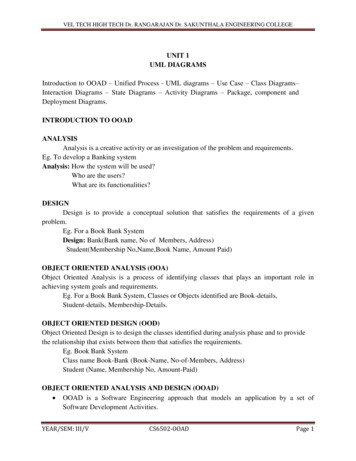
VEL TECH HIGH TECH Dr. RANGARAJAN Dr. SAKUNTHALA ENGINEERING COLLEGEUNIT IIDESIGN PATTERNSGRASP:Designing objects with responsibilities-Creator-Information Expert-Low Coupling-HighCohesion-Controller. Design Patterns-Creational-Factory y-Observer.GRASP: General Responsibility Assignment Software Patterns GRASP is a learning aid that helps to understand essential object design and apply designreasoning in a methodical, rational and explainable way. GRASP is used as a tool to help master the basics of OOD and understandingresponsibility assignment in object design. There are nine basic OO design principles in GRASP. They are,1. Creator2. Information Expert3. Low Coupling4. High Cohesion5. Controller6. Polymorphism7. Pure Fabrication8. Indirection9. Protected VariationsCREATORCreation of objects is one of the most common activities in an object oriented system. Whichclass is responsible for creating objects is a fundamental property of relationship between objectsof particular classes.ProblemWho should be responsible for creating a new instance of some class?Solution:Assign class B the responsibility to create an instance of a class A if one of these is true, B contains or compositely aggregates AB records AB closely uses AB has the initializing data for A that will be passed to A when it is created.Thus B is an expert with respect to creating AYEAR/SEM: III/VCS6502-OOADPage 18
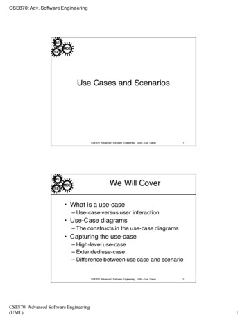
VEL TECH HIGH TECH Dr. RANGARAJAN Dr. SAKUNTHALA ENGINEERING COLLEGEB is a creator of A objectsIf more than one option applies, usually prefer a class B which aggregates or contains A.Fig: Partial Domain ModelSince a Sale contains many SalesLineltem objects, the Creator pattern suggests that Sale is agood candidate to have the responsibility of creating SalesLineltem instances.Fig: Creating a SalesLineItemThis assignment of responsibilities requires that a makeLineltem method be defined in Sale. Themethod section of class diagram can then summarize the responsibility assignment results,concretely realized as methods.YEAR/SEM: III/VCS6502-OOADPage 19
VEL TECH HIGH TECH Dr. RANGARAJAN Dr. SAKUNTHALA ENGINEERING COLLEGEINFORMATION EXPERTProblemWhat is a general principle of assigning responsibilities to objects?Solution:Assign a responsibility to the information expert-the class that has the informationnecessary to fulfill the responsibility.Fig: Partial domain model What information is needed to determine the grand total? A Sale instance contains these;therefore, by the guideline of Information Expert, Sale is a suitable class of object for thisresponsibility. The SalesLineltem knows its quantity and its associated ProductSpecification; therefore,by Expert, SalesLineltem should determine the subtotal; it is the information expert.Fig: Partial interaction and class diagrams In terms of an interaction diagram, Sale needs to send get-Subtotal messages to each ofthe SalesLineltems and sum the results.YEAR/SEM: III/VCS6502-OOADPage 20
VEL TECH HIGH TECH Dr. RANGARAJAN Dr. SAKUNTHALA ENGINEERING COLLEGEFig: Calculating the Sale total The Product Specification is an Information Expert on answering its price, thereforeSalesLineItem send it a message asking for the product price.To fulfill the responsibility of knowing and answering the sale’s total, three responsibilities wereassigned to three design classes of objects as follows.LOW COUPLINGCoupling is a measure of how strongly one element is connected to, has knowledge of, or relieson other elements. An element with low (or weak) coupling is not dependent on too many otherelements.A class with high (or strong) coupling relies on many other classes. Such classes may beundesirable; some suffer from the following problems, Forced local changes because of changes in related classes. Harder to understand in isolation. Harder to reuse because its use requires the additional presence of the classes on which itis dependent.ProblemHow to support low dependency, low change impact, and increased reuse?Solution:Assign a responsibility so that coupling remains low.YEAR/SEM: III/VCS6502-OOADPage 21
VEL TECH HIGH TECH Dr. RANGARAJAN Dr. SAKUNTHALA ENGINEERING COLLEGEEg: Partial Class domainAssume that a Payment instance is to be created and associated with the Sale. What class shouldbe responsible for this? Since a Register "records" a Payment in the real-world domain, theCreator pattern suggests Register as a candidate for creating the Payment. The Register instancecould then send an addPayment message to the Sale, passing along the new Payment as aparameter.Fig: Register creates PaymentAssignment of responsibilities couples the Register class to knowledge of payment class.Alternative solution to create payment and associate it with Sale.Fig: Sales creates PaymentIn object-oriented languages such as C , Java, and C#, common forms of couplingfrom TypeX to TypeY include: TypeX has an attribute (data member or instance variable) that refers to a TypeYinstance, or TypeY itself. A TypeX object calls on services of a TypeY object. TypeX has a method that references an instance of TypeY, or TypeY itself, by anymeans. These typically include a parameter or local variable of type TypeY, or the objectreturned from a message being an instance of TypeY. TypeX is a direct or indirect subclass of TypeY. TypeY is an interface, and TypeX implements that interface.YEAR/SEM: III/VCS6502-OOADPage 22
VEL TECH HIGH TECH Dr. RANGARAJAN Dr. SAKUNTHALA ENGINEERING COLLEGEHIGH COHESIONCohesionCohesion is a measure of how strongly related and focused the responsibilities of an elementare. An element with highly related responsibilities, and which does not do a tremendous amountof work, has high cohesion. These elements include classes, subsystems, and so on.ProblemHow to keep objects focused, understandable, and manageable, and as a side effect,support Low Coupling?Solution:Assign a responsibility so that cohesion remains high.A class with low cohesion does many unrelated things, or does too much work. Such classes areundesirable; they suffer from the following problems: Hard to comprehend Hard to reuse Hard to maintain Delicate; constantly affected by change.ExampleAssume that a Payment instance is to be created and associate it with the Sale. What class shouldbe responsible for this? Since Register records a Payment in the real-world domain, the Creatorpattern suggests Register as a candidate for creating the Payment. The Register instance couldthen send an addPayrnent message to the Sale, passing along the new Payment as a parameter.Fig: Register creates paymentThis assignment of responsibilities places the responsibility for making a payment in theRegister.YEAR/SEM: III/VCS6502-OOADPage 23
VEL TECH HIGH TECH Dr. RANGARAJAN Dr. SAKUNTHALA ENGINEERING COLLEGEFig: Sale creates PaymentCONTROLLERA Controller is the first object beyond the UI layer that is responsible for receiving or handling asystem operation message.ProblemWhat first object beyond the UI layer receives and coordinates(controls) a system operation?Solution:Assign the responsibility to a class representing one of the following choices, Represents the overall system, “a root object”, a device that the software is runningwithin, or a major subsystem. Represents a use case scenario within which the system event occurs.Example: NextGen POS applicationYEAR/SEM: III/VCS6502-OOADPage 24
VEL TECH HIGH TECH Dr. RANGARAJAN Dr. SAKUNTHALA ENGINEERING COLLEGEFig: Assigning responsibilities to controller classDuring design, a controller class is assigned the responsibility for system operation.The system Operations identified during system behaviour analysis are assigned to one or morecontroller classes, such as Register,Fig: Controller ClassBloated ControllerPoorly designed, a controller class will have low cohesion. unfocused and handlingtoo many areas of responsibility; this is called a bloated controller.Signs of bloating include: There is only a single controller class receiving all system events in the system, and thereare many of them.YEAR/SEM: III/VCS6502-OOADPage 25
VEL TECH HIGH TECH Dr. RANGARAJAN Dr. SAKUNTHALA ENGINEERING COLLEGE The controller itself performs many of the tasks necessary to fulfill the system event,without delegating the work A controller has many attributes, and maintains significant information about the systemor domain, which should have been distributed to other objects, or duplicates informationfound elsewhere.Cures for a bloated controller Add more controllers-a system does not have to have only one. For example, consider anapplication with many system events, such as an airline reservation system. Design the controller so that it primarily delegates the fulfillment of each systemoperation responsibility on to other objects.DESIGN PATTERNS Design patterns are termed as reusable solutions for commonly occurring problems insoftware designs. Design Patterns are descriptions of communicating objects and classes customized tosolve a general design problem in a particular context. Design Patterns identifies the participating classes and instances, their roles andcollaborations, and the distribution of responsibilities.Essential Elements of a pattern:1. Pattern Name2. Problem3. Solution4. ConsequencesDesign Patterns are Categorized into,1. Creational Pattern Factory Method2. Structural Patterns Bridge Adapter3. Behavioral Patterns Strategy ObserverYEAR/SEM: III/VCS6502-OOADPage 26
VEL TECH HIGH TECH Dr. RANGARAJAN Dr. SAKUNTHALA ENGINEERING COLLEGECREATIONAL PATTERNCreational design patterns provide a way to create objects while hiding the creation logic, ratherthan instantiating objects directly using new operator. This gives program more flexibility indeciding which objects need to be created for a given use case.FACTORY METHODName: FactoryProblem: Who should be responsible for creating objects when there are special considerations, such ascomplex creation logic, a desire to separate the creation responsibilities for better cohesion, and so forth?Solution: Create a Pure Fabrication object called a Factory that handles the creation.Advantages of Factory objects Separate the responsibility of complex creation into cohesive helper objects. Hide potentially complex creation logic. Allow introduction of performance-enhancing memory management strategies, such as objectcaching or recycling.In the below diagram, In ServicesFactory, the logic to decide which class to create is resolved byreading in class name from an external source and then dynamically loading the class. This is termedas Partial Data Driven Design.Fig: Factory PatternYEAR/SEM: III/VCS6502-OOADPage 27
VEL TECH HIGH TECH Dr. RANGARAJAN Dr. SAKUNTHALA ENGINEERING COLLEGEBenefits of Factory Method Factory method introduces a separation between the application and a family of classes. Itprovides a simple way of extending the family of products with minor changes in theapplication code It provides customization hooks. When the objects are created directly inside the class, itis hard to replace them by objects which extend their functionality. If a factory is usedinstead to create a family of objects that customizes objects can easily replace the originalobjects, configuring the factory to create them.Drawbacks of Factory Method The Factory has to be used for a family of objects. If the classes doesn’t extendcommon base class or interface they cannot be used in a factory design template.Uses: Factory is used to manipulate objects of same type as abstract objects. Whenever an application is designed, factory plays a vital role in creating objects.STRUCTURAL PATTERNSStructural patterns are concerned with how classes and objects are composed to form largerstructures. These patterns describe ways to compose objects to realize new functionality.BRIDGE PATTERN Bridge is used, when we need to decouple an abstraction from its implementation so thatthe two can vary independently. This type of design pattern comes under structuralpattern as this pattern decouples implementation class and abstract class by providing abridge structure between them. This pattern invol
Eg. Book Bank System Class name Book-Bank (Book-Name, No-of-Members, Address) Student (Name, Membership No, Amount-Paid) OBJECT ORIENTED ANALYSIS AND DESIGN (OOAD) OOAD is a Software Engineering approach that models an