Transcription
Chapter2ResistorsTopics Covered in Chapter 22-1: Types of Resistors2-2: Resistor Color Coding2-3: Variable Resistors2-4: Rheostats and Potentiometers2-5: Power Ratings of Resistors2-6: Resistor Troubles 2007 The McGraw-Hill Companies, Inc. All rights reserved.
2-1: Types of Resistors The two main characteristics of a resistor are itsresistance, R, in ohms and its power rating, P, in Watts. The resistance, R, provides the required reduction incurrent or the desired drop in voltage. The wattage rating indicates the amount of power theresistor can safely dissipate as heat. The wattage rating is always more than the actualamount of power dissipated by the resistor, as a safetyfactor.
2-1: Types of Resistors Types of Resistors Wire-wound resistors Carbon-composition resistors Film-type resistors Carbon film Metal film Surface-mount resistors (chip resistors) Fusible resistors Thermistors
2-1: Types of Resistors Wire Wound Resistor Special resistance wire iswrapped around an insulatingcore, typically porcelain,cement, or pressed paper. These resistors are typicallyused for high-currentapplications with low resistanceand appreciable power.Fig. 2-3: Large wire-wound resistors with 50-W powerratings. (a) Fixed R, length of 5 in. (b) Variable R,diameter of 3 in.Copyright The McGraw-Hill Companies, Inc. Permission required for reproduction or display.
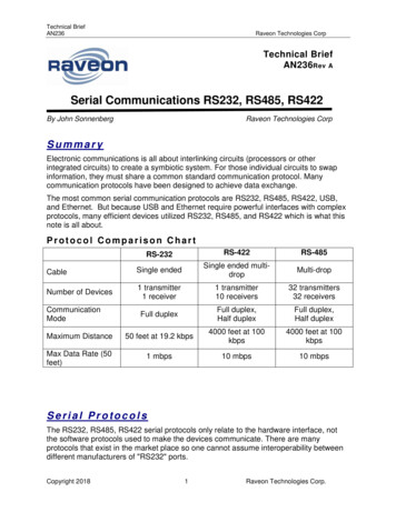
2-1: Types of Resistors Carbon Composition Resistors Made of carbon or graphitemixed with a powderedinsulating material. Metal caps with tinned copperwire (called axial leads) arejoined to the ends of thecarbon resistance element.They are used for solderingthe connections into a circuit. Becoming obsolete becauseof the development of carbonfilm resistors.Fig. 2-2: Carbon resistors with the same physicalsize but different resistance values. The physicalsize indicates a power rating of ½ W.Copyright The McGraw-Hill Companies, Inc. Permission required for reproduction or display.
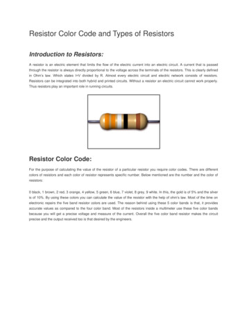
2-1: Types of ResistorsCarbon Film Resistors Compared to carboncomposition resistors,carbon-film resistors havetighter tolerances, are lesssensitive to temperaturechanges and aging, andgenerate less noise.Fig. 2-4: Construction of a carbon film resistor.Copyright The McGraw-Hill Companies, Inc. Permission required for reproduction or display.
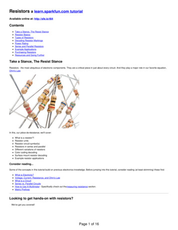
2-1: Types of Resistors Metal Film Resistors Metal film resistors havevery tight tolerances, areless sensitive totemperature changes andaging, and generate lessnoise.Fig. 2-5: Construction of a metal film resistor.Copyright The McGraw-Hill Companies, Inc. Permission required for reproduction or display.
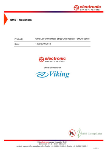
2-1: Types of Resistors Surface-Mount Resistors (alsocalled chip resistors) These resistors are: Temperature-stable and rugged Their end electrodes are soldereddirectly to a circuit board. Much smaller than conventionalresistors with axial leads. Power dissipation rating is usually1/8 to ¼ WFig. 2-6: Typical chip resistors.Copyright The McGraw-Hill Companies, Inc. Permission required for reproduction or display.
2-1: Types of Resistors Fusible Resistors: Fusible resistors are wire-wound resistors made to burnopen easily when the power rating is exceeded. Theyserve a dual function as both a fuse and a resistor.
2-1: Types of Resistors Thermistors: Thermistors are temperaturesensitive resistors whoseresistance value changes withchanges in operatingtemperature. Used in electronic circuits wheretemperature measurement,control, and compensation aredesired.Fig. 2-7b: Typical thermistor shapes and sizes.Copyright The McGraw-Hill Companies, Inc. Permission required for reproduction or display.
2-2: Resistor Color Coding Carbon resistors are small, so their R value in ohms ismarked using a color-coding system. Colors represent numerical values. Coding is standardized by the Electronic IndustriesAlliance (EIA).
2-2: Resistor Color Coding Resistor Color CodeColor Code0 Black1 Brown2 Red3 Orange4 Yellow5 Green6 Blue7 VioletFig. 2-8: How to read color stripes oncarbon resistors for R in ohms.Copyright The McGraw-Hill Companies, Inc. Permission required for reproduction or display.8 Gray9 White
2-2: Resistor Color Coding Resistors under 10 Ω: The multiplier band is either gold or silver. For gold, multiply by 0.1. For silver, multiply by 0.01.Fig. 2-9: Examples of color-coded R values, with percent tolerance.Copyright The McGraw-Hill Companies, Inc. Permission required for reproduction or display.
2-2: Resistor Color Coding Applying the ColorCode The amount bywhich the actualR can differ fromthe color-codedvalue is itstolerance.Tolerance isusually stated inpercentages.Gold 5%5% of 4700 2354700 - 235 4465Yellow 44700 235 4935Violet 7Red 2The actual value can range from 4465 to 4935 Ω.4770000Ωis the nominal value.
2-2: Resistor Color Coding What is the nominal value and permissible ohmicrange for each resistor shown?1 kΩ (950 to 1050 Ω)390 Ω (370.5 to 409.5 Ω)22 kΩ (20.9 to 23.1 kΩ)1 MΩ (950 kΩ to 1.05 MΩ)
2-2: Resistor Color Coding Five-Band Color Code Precision resistors often use afive-band code to obtain moreaccurate R values. The first three stripes indicatethe first 3 digits in the R value. The fourth stripe is themultiplier. The tolerance is given by thefifth stripe. Brown 1%Red 2%Green 0.5%Blue 0.25%Violet 0.1%.Copyright The McGraw-Hill Companies, Inc. Permission required for reproduction or display.Fig. 2-10: Five-band code.
Problem 2-6 Using the five-band code, indicate the colors of thebands for each of the following resistors:a) 110 Ω 1%b) 34 kΩ 0.5%c) 82.5 kΩ 2%Color CodeToleranceBrown 1%Red 2%Green 0.5%Blue 0.25%Violet ioletGrayWhite
2-2: Resistor Color Coding Zero-Ohm Resistor Has zero ohms ofresistance. Used for connecting twopoints on a printed-circuitboard. Body has a single blackband around it. Wattage ratings aretypically 1/8- or 1/4-watt.Fig. 2-11: A zero-ohm resistor isindicated by a single black color bandaround the body of the resistor.Copyright The McGraw-Hill Companies, Inc. Permission required for reproduction or display.
Chip Resistor Coding SystemBody color is usually white or off-whiteEnd terminals are C-shapedThree (four) digits on the body or on the filmFirst 2 (3) digits indicate the first two (three) numbersThird (fourth) digit indicates the multiplierAre available in tolerances of 1% 5% but tolerancesare not indicated on the chip The letter R is used to signify a decimal point forvalues between 1 to 10 ohms (1R5 means 1.5 ohms)
2-3: Variable Resistors A variable resistor is a resistor whose resistance valuecan be changed.Copyright The McGraw-Hill Companies, Inc. Permission required for reproduction or display.
Variable resistors Decade resistance box Provides any R within a wide range ofvalues First dial is the units or R 1 dial. Second dial is the tens or R 10 dial The hundreds or R 100 dial has an R of0 to 900Ω Etc. Dials are connected internally so that theirvalues add to one another.
Problem Indicate the total resistance of a decade resistorwhose dial settings are as follows: R 100 k is set to 6 R 10 k is set to 8 R 1 k is set to 0 R 100 is set to 2 R 10 is set to 8 R 1 is set to 0
2-4: Rheostats and Potentiometers Rheostats and potentiometers are variable resistances usedto vary the amount of current or voltage in a circuit. Rheostats: Two terminals. Connected in series with the load and the voltage source. Varies the current.Copyright The McGraw-Hill Companies, Inc. Permission required for reproduction or display.
2-4: Rheostats and Potentiometers Potentiometers: Three terminals. Ends connected across the voltage source. Third variable arm taps off part of the voltage.Copyright The McGraw-Hill Companies, Inc. Permission required for reproduction or display.
2-4: Rheostats and PotentiometersRheostats are two-terminal devices.Wiper armWiping contactFixed contactCopyright The McGraw-Hill Companies, Inc. Permission required for reproduction or display.
2-4: Rheostats and Potentiometers Using a Rheostat to Control Current Flow The rheostat must have a wattage rating high enoughfor the maximum I when R is minimum.Fig. 2-17: Rheostat connected in series circuit to vary the current I. Symbol for the current meteris A, for amperes. (a) Wiring diagram with digital meter for I. (b) Schematic diagram.Copyright The McGraw-Hill Companies, Inc. Permission required for reproduction or display.
2-4: Rheostats and Potentiometers Potentiometers Potentiometers are threeterminal devices. The applied V is input tothe two end terminals ofthe potentiometer. The variable V is outputbetween the variable armand an end terminal.Fig. 2-18: Potentiometer connected across voltagesource to function as a voltage divider. (a) Wiringdiagram. (b) Schematic diagram.Copyright The McGraw-Hill Companies, Inc. Permission required for reproduction or display.
Problem 2-8 Show two different ways to wire a potentiometer sothat it will work as a rheostat.
Potentiometer Used as a Rheostat A potentiometer may beused as a rheostat bysimply using the wiperterminal and one of theother terminals, the thirdterminal is left unconnectedand unused Another method is to wirethe unused terminal to thecenter terminal
2-5: Power Rating of Resistors In addition to having the required ohms value, a resistorshould have a wattage rating high enough to dissipatethe power produced by the current without becomingtoo hot. Power rating depends on the resistor’s construction. A larger physical size indicates a higher power rating. Higher-wattage resistors can operate at highertemperatures. Wire-wound resistors are physically larger and havehigher power ratings than carbon resistors.
Good to Know Maximum allowable current for any resistance setting iscalculated as:I max PR Maximum voltage which produces the rated powerdissipation can be calculated as:Vmax P.RP and R are the rated value of rheostatQ. What is Imax of a 5-KΩ 2-W rheostat?
2-6: Resistor Troubles Resistors can become open or they can drift out oftolerance. Some controls (especially volume and tone controls)may become noisy or scratchy-sounding, indicating adirty or worn-out resistance element. Due to the very nature of their construction, resistorscan short out internally. They may, however, becomeshort-circuited by another component in the circuit.
2-6: Resistor TroublesAn open resistor measures infinite resistance. ΩAn example of an out-of-tolerance resistor:1 kΩ,5% nominal1.5 kΩ
2-6: Resistor Troubles Resistance measurements are made with anohmmeter. The ohmmeter has its own voltage source, so voltagemust be off in the circuit being tested. Otherwise theohmmeter may become damaged.
2-6: Resistor Troubles All experienced technicians have seen a burnt resistor. This is usually caused by a short somewhere else in thecircuit which causes a high current to flow in theresistor. When a resistor’s power rating is exceeded, it can burnopen or drift way out of tolerance.
Critical Thinking Problem A manufacturer of carbon-film resistors specifies amaximum working voltage of 250V for all its ¼-Wresistors. Exceeding 250 V causes internal arcingwithin the resistor.Above what minimum resistance will the maximumworking voltage be exceeded before its ¼-W powerdissipation is exceeded?
2-2: Resistor Color Coding Applying the Color Code The amount by which the actual R can differ from the color-coded value is its tolerance. Tolerance is usually stated in percentages. 4700 ΩΩΩΩ is the nominal value. Violet 7 Red 2 Gold 5% 5% of 4700 235 4700 235 4935 4700 - 235 4465 The actual value can range from 4465 to 4935 .