Transcription
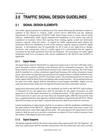
SECTION 22.0 TRAFFIC SIGNAL DESIGN GUIDELINES2.1SIGNAL DESIGN ELEMENTSAny traffic signal proposed for installation on City streets shall meet the minimum criteria asoutlined in the Manual on Uniform Traffic Control Devices (MUTCD) and the AlabamaDepartment of Transportation (ALDOT) Traffic Signal Design Guide & Timing Manual, latesteditions. Additionally, traffic signals proposed for installation on City streets may only beconsidered at locations where their spacing from existing signals would not deteriorateroadway capacity along the street. A request for traffic signalization shall address theminimum criteria for installation as well as the roadway capacity impacts created by signalspacing. A development may be responsible for all or part of any right-of-way, design,hardware, and construction costs of a traffic signal if it is determined that the signal iswarranted by the traffic generated from the development. The procedures for traffic signalinstallation shall be in accordance with criteria established by the MUTCD and ALDOT, asapplicable.2.1.1Signal HeadsAll signal lenses shall be DIALIGHT (or approved equal) twelve (12) inch LED balls with aquick disconnect feature utilizing a fork terminal end for termination purposes. The LEDlenses shall be wired to a terminal block located in the yellow lens housing. The LED lensesshall be installed in a yellow aluminum signal head housing with yellow aluminum tunnelvisors. Back plates are typically not required on City signals unless a visibility problem exists.Back plates are required by ALDOT on all State routes. All mounting hardware for mast armtraffic signals shall be black Pelco articulating cable mount brackets. All mounting hardwarefor span wire traffic signals shall be aluminum tri-stud hanger assemblies. Signal wire formast arm intersections shall enter through the bracket and not be externally exposed.Signal head placement shall adhere to the standards set forth in the MUTCD, latest edition.A minimum of two (2) signal faces shall be provided for the major movement on eachapproach, even if the major movement is a turning movement. If the signal faces providedon the mast arm or span wire are more than one hundred eighty (180) feet beyond the stopline, a supplemental near side signal face shall be installed as required by the MUTCD. Wheredual left turn lanes are provided, a separate left turn face shall be provided for each lane.Lateral positioning of signal heads shall be in accordance with the guidelines established inthe latest edition of the MUTCD. Adjacent signal faces on the same mast arm or span wireshall be placed no closer than eight (8) feet apart. The placement of the signal head over theroadway shall be such as to provide a minimum seventeen (17) foot vertical clearance fromthe bottom of the signal head to the roadway.2.1.2Signal SupportsAll signals supports shall be decorative mast arms unless approved by the City Engineer. Allmast arm signal poles shall be smooth, round poles with an arched mast arm and a powderLATEST REVISION: JANUARY 1, 20182-1
2. TRAFFIC SIGNAL DESIGN GUIDELINEScoated gloss black (P-33) finish. Poles are to be assembled with the ornamental pole base andornamental pole top per the City standards. The factory finish on the ornamental ball on poletop shall be gloss black on all assemblies.Strain poles and mast arm poles should be located as far as practical off the edge of roadwaywhile staying within the right-of-way. Additionally, the poles shall be located to maximizethe separation between the foundation and existing utilities. The location of strain poles andmast arm poles shall be in compliance with the AASHTO Roadside Design Guide and ALDOTstandards, and approved by the City Engineer.2.1.3Cabinet and Controller EquipmentThe standard controller to be used at all signalized intersections shall be an Eagle or approvedequal 16-phase, NEMA-compatible controller that meets current ALDOT standards andspecifications. Controller cabinets shall be 16-phase powder coated gloss black groundmounted cabinets with railroad preemption and remote traffic signal override cord, unlessotherwise approved by the City Engineer. The controller cabinet shall be so oriented that thetraffic personnel will be facing the intersection while looking in the cabinet. Controllercabinets should be located as far as practical off the edge of the roadway and in the sameintersection quadrant as the power source. Cabinet shall have integrated UPS cabinet unlessapproved by Traffic Engineer. All cabinet components and controller shall be capable ofoperation with flashing yellow arrow sequencing. All cabinet pedestals shall be constructedwith a spare 2” conduit stubbed out for future use.2.1.4 CommunicationsSignal interconnect provides communication between two (2) or more individual trafficsignals to provide coordination of signals. The different types of communication includehardwire, twisted pair, closed-loop and radio. Other types of communication may beconsidered and approved at the discretion of the City Engineer. When an intersection withexisting communications equipment is modified or upgraded, the existing communicationequipment shall be reinstalled in the newly completed signalized intersection and fullyfunctional unless new communication equipment is specified in the project plans anddocuments.2.1.4.1Extension of Existing SystemIf a new signal is to be added to an existing hardwire connection, a local controller withadequate cabinet space for an interconnect panel must be designated as the systemsupervisor. If the signal modifications are significant, the replacement of the hardwiresystems with a more advanced interconnect system may be necessary.To connect a new signal with an existing twisted pair connection, a local controller must bedesignated as the system supervisor and communications boards must be installed in eachcontroller.If a new signal is to be added to an existing closed-loop system or if an existingcommunication system is being upgraded to a closed-loop system, all controllers must beof the same make or all controllers must be upgraded.LATEST REVISION: JANUARY 1, 20182-2
2. TRAFFIC SIGNAL DESIGN GUIDELINES2.1.4.2New System ImplementationClosed-loop systems and radio interconnect systems are most common for newinstallations. Radio signals require a clear line of sight between antennas and transmissionsmay be disrupted by rolling terrain, dense tree canopies and/or tall building structures. Aclosed-loop twisted pair interconnect system may be installed underground.2.1.5Signal Wiring, Conduit and Junction BoxesAll signal head wiring is required to be seven (7) conductor stranded, regardless of signalhead (3-, 4- or 5- section heads).Wiring from cabinet to signal heads should have no joints.Terminations are to be made in signal heads and cabinets only. Any changes to an existingintersection with solid wiring will require complete re-wire of all components using strandedcable. At existing span wire intersections, removal of existing lashing may be required whennew wire is added. Adding new wire over existing lashed wire shall not be permitted unlessold lashing is removed. Lashing shall be aluminum lashing tape only.A minimum of two (2) – 2” conduit are required for signal cable from the controller cabinetunder roadways. Two (2) – 2” conduit is also required for signal cable and loop returns, oncethe run has crossed the roadway. All above ground conduit is required to be rigid metallic,while PVC Schedule 40 conduit is the standard for trenched underground conduit andcontinuous run HDPE conduit is the standard for underground bored conduit. A spare 2”conduit shall be stubbed out of each pole foundation and the cabinet pedestal for future use.Traffic rated junction boxes of a minimum size of 17”x 30” and minimum Tier 15 rating arerequired for all installations throughout the City, regardless of location within the right-ofway. Junction box lids shall have “traffic” molded into the lid. Any joints within undergroundjunction boxes shall be water-tight connectors and approved by the Traffic Engineer.2.1.6Power SupplyThe electrical power source for the controller cabinet shall be underground. It shall bedesignated on signal plans in the same quadrant as the signal controller. The power sourceshould be verified by the engineer in the field with a representative of the power companybefore the power source is located on the plans. The service disconnect shall be black andconstructed in accordance with the standard detail shown in Appendix H Any chargesimposed by the utility company for service shall be paid by the project contractor or signalcontractor.An uninterruptible power system (UPS) (battery back-up system Clary SP 1250LX orapproved equal) is required for all intersections. The entire UPS system and batteries shall behoused in the traffic signal controller cabinet with integrated UPS cabinet. When added to anexisting cabinet without space for the UPS, the UPS and batteries shall be housed in a 336Scabinet. The UPS shall use the OP72C battery. Aesthetics should be considered whendesigning the location and style of the power service supply and disconnect to maintain thestandard established by the decorative black poles.LATEST REVISION: JANUARY 1, 20182-3
2. TRAFFIC SIGNAL DESIGN GUIDELINES2.1.7Vehicle DetectionThe type of vehicle detector used depends upon the type of information needed by thecontroller to operate efficiently at its location with respect to the roadway. There are two (2)types of inductive loop detectors, as well as video detection, which are acceptable for usewithin the City. The type of detection used at each intersection shall be approved by the CityEngineer. Video detection shall be required at all new or improved intersections. Other typesof detection may be considered and approved at the discretion of the City Engineer. Alldetection, regardless of type, shall be capable of obtaining and providing volume data via themesh network and shall detect and respond to the presence of bicycles.The inductive loop detects vehicles by sensing a change of inductance in the loop caused bythe passage or presence of a vehicle over the loop. This type of detection is made up of three(3) components: a loop of wire sawcut into the roadway surface, a lead-in (home run) cableand an amplifier unit in the controller cabinet. It is capable of both passage and presencedetection. All loops sawcut into the road way shall have individual homerun cables andindividual curb side cut outs. Loops shall be installed and tested in accordance with ALDOTStandard Specification 730(p). Testing results for each loop shall be provided to the TrafficEngineer for approval.Video detection utilizes video cameras and an image processor to detect the presence of avehicle to determine when to activate a particular phase.2.1.7.1Stop Line DetectionStop line detection, as the name implies, are inductive loops located at or near the stop lineon an intersection approach to detect the presence of stopped vehicles and operate in thepresence (non-locking memory) mode of detection. Stop line detection is typically used onlow speed [twenty-five (25) mph or less] and side street approaches. They are typically usedin through lanes on minor approaches (at a minimum), in left turn lanes on both major andminor approaches and across bicycle lanes. When used with a delay, stop line detectors canscreen out right turns made on red, or left turns clipping opposing lanes, thus preventingfalse calls.The standard size loop is six (6) feet by forty (40) feet regardless of lane widths. At largeradius intersections, wider loops may be used. The width of the loop in a curbside lane canincrease significantly when it is located ten (10) feet back from a cross street and theintersection has large curb radii.2.1.7.2Advanced DetectionAdvanced detection are inductive loops that can be used with volume density controllersand are located some distance in advance of the approach stop line. The advanced loop issix (6) feet by six (6) feet and located in the through lanes of the major street where speedsare thirty (30) mph or greater. These loops operate in a passage or pulse mode and detectvehicles as they pass a specific point. Advanced loop detection can provide the controllerwith information on vehicles approaching the intersection, and in the case of a volumedensity controller, can count the number of vehicles on the approach that are waiting withLATEST REVISION: JANUARY 1, 20182-4
2. TRAFFIC SIGNAL DESIGN GUIDELINESa red signal indication. The location of these loops is based on the safe stopping distance ofapproaching vehicles which varies according to the approach speed.TABLE 2.1Advanced Detector LocationApproach SpeedLoop Setback30 mph140’35 mph185’40 mph230’45 mph285’50 mph340’55 mph405’Source: ITE Manual of Traffic Signal Design, 2nd Edition2.1.7.3Video DetectionVideo detection can operate in both presence and passage mode, similar to stop line andadvanced detection. Detection zones are designated in the image processor to detect thepresence of a vehicle and a bicycle and send a call to the controller. Video detection is oftenused in place of stop line detection, but can also be used for advanced detection (mayrequire cameras downstream of the intersection). If the intersection cameras cannot detectadvancing vehicles because of the topography and additional downstream cameras are notfeasible, advanced loops may be necessary.The latest model color Ieteris camera and VRack (mounting rack) are required at allintersections operating with a video detection system. Cameras are to be mounted on amast arm on the far side of the intersection. Proper mounting height is necessary, and variesby location, to ensure the cameras have an acceptable field of vision. ALDOT recommendsmounting heights from thirty (30) to forty-two (42) feet. Engineering judgment is requiredto determine the ultimate mounting location. All cameras and mounting hardware for videodetection shall be black. Powder coated black cable mount brackets shall be used formounting.2.1.7.4Wireless DetectionWireless detection shall be compatible with and interchangeable with the existing wirelesssystems provided by Sensys Networks.2.1.8Railroad Pre-EmptionThe MUTCD states that railroad pre-emption shall be provided whenever the distancebetween a rail crossing and traffic signal is two hundred (200) feet or less. Additionalwarrants include: Analysis that indicates vehicle queues from a traffic signal have the potential toextend into or past the rail crossing, and Analysis that indicates vehicle queues caused by a passing train have thepotential to extend into the signalized intersection and obstruct traffic flow.LATEST REVISION: JANUARY 1, 20182-5
2. TRAFFIC SIGNAL DESIGN GUIDELINESThe maximum [ninety-five (95%) percent] queue is recommended to be used whendetermining whether the queue will extend into the track area [within eight (8) feet of thenearest rail]. Refer to ALDOT’s Traffic Signal Design Guide & Timing Manual for the standardpre-emption sequence and guidelines for computing the minimum interval times.2.1.9Intersection SignageThis section presents only the most commonly required signing associated with traffic signals.Guidance for additional signing may be found in the MUTCD, latest edition.Spanwire/Mast arm mounted sign arrangements shall be installed in conformance with theMUTCD, latest edition. Where overhead signs are installed, they shall have a minimum ofseventeen (17) foot vertical clearance over the roadway. Examples of these signs include:1.2.3.4.Left Turn Signal Signs R10-10, R10-12,Lane Control Signs R3-5 through R3-6a,Turn Prohibition Signs R3-1, R3-2, R3-4, R10-5, R10-11a,Street Name Signs D3-1.Ground mounted signs to be used at or in advance of signalized intersections shall be installedin conformance with the MUTCD, latest edition. Examples of these signs include:1. Turn Lane Supplemental Sign R3-7,2. Signal Ahead Sign W3-3,3. Street Name Signs D3-2.Street name signs shall be LED internally edge lit illuminated signs with high intensityprismatic white letter on the standard City of Auburn blue background. They shall beequipped with flip front faces for field maintenance. Frames shall be gloss black in color. Allmounting hardware for illuminated signs shall be black under-hang brackets for use withtwo-sided signs. Each individual sign shall be fused at the base of the pole unless otherwiseapproved by the Traffic Engineer. One black photoelectric cell shall be located on the bottomof the disconnect to control both signs.Traffic control signs used at signalized intersections in the City shall be high intensityprismatic and of the size specified in the MUTCD. The unit measurement for these signs asshown in signal plans shall be in square feet of sign face.2.1.10 Pedestrian SignalPedestrian signals shall be LED countdown signal heads (Lumination PS7-CFF1-01A-18),with a “walking person” indication and a “flashing/steady upraised hand”. Audible devicesshall also be installed to provide standard information about the status of the signal cycle topedestrians with disabilities. Pedestrian signal housing shall have a gloss black finish. Allmounting hardware for pedestrian signal heads shall be black clam-shell brackets drilled andtapped to the pole.Pedestrian push buttons shall be provided on their own individual poles on the appropriateapproach with an audible push button for each crossing direction. Pedestrian push buttonpoles shall be installed in accordance with the standard detail shown in Appendix H.LATEST REVISION: JANUARY 1, 20182-6
2. TRAFFIC SIGNAL DESIGN GUIDELINESPedestrian push buttons shall be POLERA Navigator (or approved equal) compliant withPublic Rights-of-Way Accessibility Guidelines’ (PROWAG) issued by the United StatesAccess Board. Each push button is to be supplemented by sign R10-3i, which includes thestreet name of the street to be crossed with an arrow pointing in the direction of the crossing.The street name shall also be identified in Braille. Audible push button programming shall beimplemented in accordance with the latest edition of the MUTCD including all individualstreet names and messages. Standard Polera settings for volume and tones may be obtainedfrom the Traffic Engineering Department.The pedestrian signal phase is a special sequence actuated by pedestrian push buttons toallow pedestrians to safely cross a street.2.1.10.1 WarrantsA pedestrian signal phase with pedestrian signal heads shall be installed when any of thefollowing occur:1.2.3.4.When Signal Warrant 4, “Pedestrian Volume” is fulfilled,When Signal Warrant 5, “School Crossing” is fulfilled,Where there is an established school crossing at the proposed signal location,Where pedestrians are present and multiphase signal operations (lead-lag leftturns, split phasing, etc.) are used that could confuse the pedestrians,5. Where a sidewalk approaches the intersection on opposite sides of theintersection and on the same side of the street.6. As required by the City Engineer.2.1.10.2 SequenceThe most commonly used sequence is to move pedestrians concurrent with parallelvehicular traffic. Care must be taken however not to move pedestrians during the displayof a conflicting left turn or right turn arrow for the parallel vehicular traffic. The exclusivemovement sequence moves pedestrians on a phase totally separate from any vehicularphase. When used, pedestrians cross all approaches simultaneously. This sequence shouldonly be used where both pedestrian volumes and conflicting vehicular turning movementvolumes are high.2.1.10.3 TimingWalk timing provides the time necessary for a pedestrian to leave the curb to cross the street.Its minimum setting ranges from three (3) to seven (7) seconds. Pedestrian clearance timeshall be calculated utilizing the latest edition of the MUTCD. It is calculated using theequation:PC W / V PWhere:PC Pedestrian Clearance (sec)W Width of street (ft)V P Pedestrian walking speed (see MUTCD latest edition)A portion of the pedestrian clearance interval can be timed simultaneously with the yellowand all red intervals of the concurrent vehicular phase.LATEST REVISION: JANUARY 1, 20182-7
2. TRAFFIC SIGNAL DESIGN GUIDELINES2.1.11 Intersection LightingA twelve (12) foot luminaire arm with a Phillips Roadstar 130 130W98LED4K (or approvedequal) cobra head fixture shall be installed on all traffic signal poles at the intersections.Luminaire assembly shall be painted with a gloss black finish and include an equivalent to atwo hundred fifty (250) watt high pressure sodium fixture. Each fixture shall be individuallyfused at the base of the pole.LATEST REVISION: JANUARY 1, 20182-8
2. TRAFFIC SIGNAL DESIGN GUIDELINES2.2SIGNAL TIMINGTraffic signal timings shall be developed in accordance with the criteria established by theMUTCD, Federal Highway Administration (FHWA) Traffic Signal Timing Manual and theALDOT Traffic Signal Design Guide & Timing Manual, latest editions. The engineer shouldconsult with the City Traffic Engineer to determine whether a traffic signal will operate asactuated. Fixed time signals are often used in the downtown area and on low volume roads.Actuated signals with a fixed cycle length are more commonly used.2.2.1Cycle LengthsSignal cycle length is the total time required to complete one (1) sequence of signal phasesand generally should be as short as possible. Table 2.2 “Typical Cycle Length Ranges”contains guidelines regarding typical cycle length ranges. Cycle lengths should be calculatedfor the A.M. peak hour, the P.M. peak hour and off peak periods, as a minimum. If the cyclelengths vary by more than ten (10) seconds, each period should operate on a different cyclelength. Signal timing software should be utilized to determine optimum cycle lengths.TABLE 2.2Typical Cycle Length RangesTraffic VolumesTypical CycleLength RangeLow50 – 90 sec.Moderate/High90 – 130 sec.Congested130 – 180 sec.Source: ALDOT Traffic Signal Design Guide and Timing Manual, November 20072.2.2Actuated Timing ParametersThe following timing parameters are for stop line detection of an actuated signal: minimumgreen, vehicle extension (passage time), maximum green (I and II), yellow all red, walk andpedestrian clearance. The following timing parameters are for advanced detection of avolume density signal controller. These features are typically used for approach speeds thirty(30) mph or greater and provide a variable (minimum) green as well as a variable “gap”feature. The timing parameters are: minimum initial (minimum green), added initial, initialgap (passage time), time before reduction, time to reduce, minimum gap, maximum green (Iand II), yellow, all red, walk and pedestrian clearance.2.2.3Signal Timing PlansA signal timing plan is the combination of cycle length, phasing, splits (green clearance foreach phase) and offsets (for coordinated systems) and should be included with traffic signalplans.LATEST REVISION: JANUARY 1, 20182-9
2. TRAFFIC SIGNAL DESIGN GUIDELINES2.3PLANS PRODUCTIONA Traffic Signal Plans Submittal Checklist has been provided in Appendix F to facilitate amore efficient plan review process for the designer and the review team. The checklist mustbe submitted with every set of plans for traffic signal improvements or new signalinstallations. The various signal plan sheets, their format and contents are described in thissection. At a minimum, all plan sheets shall have a title block containing the intersection orcorridor name, a scale, the design date and the design firm information, including the initialsof the designer. The title sheet shall be stamped, signed, and dated by the engineer of recordthat supervised the design and plans production.2.3.1Traffic Signal NotesThis sheet contains, as the name implies, notes of general nature that apply to all thesignalized intersections in the plans. It generally includes items from the ALDOT StandardSpecifications for Highway Construction (latest edition) for which emphasis is intended forthe contractor. The most frequently used notes are shown in Appendix G.2.3.2Signal PlanSignal plan sheets shall illustrate the basic intersection geometry, channelization, driveways,ditches, right-of-way, the location of underground and aerial utilities, utility poles, pavementmarkings, construction stationing (if available), and the power source for the controllercabinet.The following information concerning the timing, phasing and installation of the signal is alsorequired on the signal plan sheet.2.3.2.1Installation NotesThis set of notes applies to the signal installation at a particular intersection only. It shouldnot repeat notes covered in the signal general notes section. Items typically covered in thesenotes include but are not limited to: 2.3.2.2Signal Controller/Cabinet – Specifies installation and typeElectrical Service – Specifies installationJunction Boxes – Specifies installation and typeSignal detectors – Specifies installationReferences – Refers to the signal General Notes and the signal timing andoperations sheets for additional informationSpeed Limits – Posted speed limits on all intersection approachesFlashing Operations – Yellow to major street, red to minor street.Signal Head DisplaysThis diagram shows the signal indication arrangement for each head on the signal plan. Italso specifies the signal indication lens size twelve (12) inches and signal head housing color(yellow).LATEST REVISION: JANUARY 1, 20182-10
2. TRAFFIC SIGNAL DESIGN GUIDELINES2.3.2.3Signage Displays2.3.2.4Pre-Emption Phasing Diagram2.3.2.5Signal Sequence Chart2.3.2.6Conflict Monitor Chart2.3.2.7Wiring Diagram and TableThis diagram shows the sign type, MUTCD designation and size for each sign called for onthe signal plans. If a non-standard sign, such as a street name sign, is called for, its size,color and legend must be specified.If emergency or railroad pre-emption is included in the signal design, a pre-emptionphasing diagram is needed to show all the phasing sequences possible when the signal ispre-empted. The phase in which normal operations is to resume after pre-emption is to bedesignated. Normally pre-emption is limited to major roadways and not side streets.Exceptions would be if there was a fire/EMS station or hospital located on the side street.This table contains all the timing parameters applicable for the type of signal specified inthe plans. The timing is shown for each signal phase in addition to its recall status.The conflict monitor chart contains the permissible or safe phase combinations to behardwired into the conflict monitor. Any combination not wired into the circuit board willtrip the conflict monitor and place the signal into flash mode.The wiring diagram shows the wiring required to accommodate the signal heads, detectors,signal controllers and power source for the signal installation shown on the signal plan. Forclarity purposes, the combination of conductors required in each different section of thewiring diagram may be designated with a letter code corresponding to a wiringcombination shown in the wiring table.The wiring table is a chart that describes the various conductor combinations as designatedby the letter code on the wiring diagram. The wiring code should include all runs bothaerial and underground. It also specifies the conduit size needed for each particularcombination of conductors run underground.2.3.2.8Materials ListThis chart shall list the components of the signal equipment that are covered under the 730“Furnishing and Installing Traffic Control Unit” pay item. Computed quantities are notnecessary as they are part of a lump sum pay item. The following items, as applicable,should be listed in a box on the plan sheet: 3/8” messenger cable1/4” tether wire#14 signal cablePower source (specify 120V or 240V)Miscellaneous hardwareSpan mounted signs with hardware (ex. R10-12, R10-10, etc.)Backplates with hardwareWeatherheadsPedestrian signal displaysLATEST REVISION: JANUARY 1, 20182-11
2. TRAFFIC SIGNAL DESIGN GUIDELINES 2.3.3Pedestrian pushbutton assemblies.Details and Standard DrawingsThe traffic signal plans shall also include all standard details, drawings and specifications asapplicable to the signal design. This includes, but it not limited to the City’s StandardDecorative Pole Assembly and the applicable ALDOT Traffic Signal Operating Plan. Typicaldetails, drawings and specifications are provided in Appendix H of this Manual.2.3.4Communication PlanA communication or interconnect plan shall be required if a traffic signal is being coordinatedwith other signal installations, via hardwire, radio, fiber optic or other. The plan shallillustrate required equipment such as master controllers, and the placement ofcommunication cable, either underground or aerial, and tabulate all related interconnectquantities. The communication plan sheet shall indicate all signal and/or utility poles towhich communication cable will be attached. In the case of radio coordination, the plan shallillustrate all necessary antennae, master controllers or other required equipment.LATEST REVISION: JANUARY 1, 20182-12
2. TRAFFIC SIGNAL DESIGN GUIDELINES2.4CONSTRUCTIONA certified Traffic Signal Technician shall have active involvement with all work required forthe installation and operational testing of electrical materials and equipment (conduit, boxes,conductors, etc.).All installations shall comply with the regulations of the National Electrical Code and theNational Electrical Safety Code, latest editions, and with the service rules of the electric serviceprovider. Prior to beginning work, contractors shall provide at least 48 hours notification tothe Traffic Engineering Department.In the case of a signal upgrade, existing equipment that is not in operation at the project siteshall be returned to the Public Works Department.2.4.1Mater
All signal lenses shall be DIALIGHT (or approved equal) twelve (12) inch LED balls with a quick disconnect feature utilizing a fork terminal end for termination purposes. The LED lenses shall be wired to a terminal block located in the yellow lens housing. The LED lenses