Transcription
Lighting Design Guidelines20201.Introduction . 21.1Guideline Overview . 21.2When to Use This Guideline . 31.3Lighting Selection . 32.Lighting Applications. 42.1Rural vs. Urban Lighting. 42.2Special Lighting Applications . 52.2.1Freeways, Viaducts, and Flyovers . 62.2.2Complete Interchanges . 82.2.3Partial Interchanges .102.2.4Highway Underpasses .122.2.5Tunnels .132.2.6Roundabouts .162.2.7Unincorporated Streets .172.2.8Pedestrian and Bicycle Pathways .192.2.9Crosswalks .212.2.10 CDOT Park and Ride facilities .232.2.11 Rest Areas .252.2.12 Chain-up and Chain-down Areas .272.2.13 Solar Roadway Lighting .292.2.14 Temporary Roadway Lighting .302.2.15 Temporary Construction Lighting .322.2.16 Political Boundary Sign Lighting .333.Lighting Controls .353.1Dimming .353.2Photocontrol Receptacles and Control Nodes .353.3Lighting Control Centers and Meter Power Pedestals .364.Lighting Fundamentals .374.1Visibility.374.2Common Luminaire Classifications .424.3BUG Ratings .424.4Lighting Equipment .434.5Design Configurations.454.6Pedestrian Area Classification .474.7Calculation Parameters .474.8Maintenance and Economics .495.Glossary and References .505.1Glossary .505.2References .55
Lighting Design Guidelines202011.The CDOT Lighting Design Guidelines represent the current recommended practices for roadwaylighting and includes criteria for typical applications found in the State of Colorado. It is based onthe Illuminating Engineering Society (IES) Lighting Handbook Tenth Edition, the AmericanNational Standard Practice for Design and Maintenance of Roadway and Parking Facility Lighting(ANSP/IES RP-8-18), and the American Association of State Highway and TransportationOfficials (AASHTO) 2005 Roadway Lighting Design Guide. The CDOT Lighting Design Guidelinesshould be used in conjunction with the latest version of these references. Exceptions to theseguidelines should be thoroughly evaluated and documented in accordance with CDOT’s designexception policies.The guidelines were developed, prepared, andreviewed in 2019 by Clanton and Associates,Inc. and a team of CDOT engineers representingall CDOT regions.Comments on this Design Guide may be sent toColorado Department of TransportationTraffic and Safety Engineering Branch2829 W. Howard Pl.Denver, Colorado 80204303-757-9654The lighting justification listed in these guidelinesare taken from the AASHTO Roadway LightingDesign Guide lighting warrants. The meeting ofAASHTO lighting warrants does not obligate theDepartment to undertake a lighting project on either existing or proposed highways. Thejustification for lighting should be based on conditions relating to the need for roadway lightingand the benefits that may be derived from lighting.These guidelines use standard US Customary units (inch-feet-mile). One exception to this formatis made when discussing candela / square meter (cd/m2), the unit of lighting luminance. TheEnglish term for this unit, footlamberts, is no longer current in the lighting industry. While this isinconsistent with the other US Customary units, all luminance criteria are given in cd/m2.The purpose of roadway lighting is to improve nighttime visibility by lighting roadway conflict points,pedestrians in crosswalks, fixed objects, or obstructions on the roadway. A good lighting systemthat can improve nighttime visibility will have effective, high quality light of an appropriate quantity
Lighting Design Guidelines2020with minimal glare. Effective lighting refers to the ability of the light to provide contrast betweenobjects and surroundings so that motorists can detect conflicts in time to take evasive action.The roadway lighting system design is based on pavement luminance. Luminance is defined asthe amount of light reflected from a surface that the eye perceives (in cd/m2). More specifically,pavement luminance refers to how bright the pavement appears. Luminance quantifies the visualenvironment with respect to how a motorist will view it. Another metric used in roadway lightingdesign is illuminance, which is defined as the amount of light that reaches a surface, in footcandles(fc). Curving roadway sections, such as partial interchanges, are based on illuminance due tocalculation software limitations. Intersections and pedestrian pathways are also based uponilluminance, both horizontal and vertical. Illuminance, while easy to calculate and an initial startingpoint in the design process, does not quantify what a motorist sees and is not used as the lightingcriteria in most roadway applications.In addition to providing adequate visibility, roadway lighting design must address the importanceof operation and maintenance. Typical operation and maintenance issues includes life of the lightsource, durability of the luminaire, access to the luminaire due to both location and height of thelight standard, and availability of replacement parts. Some control systems can simplify themaintenance process by providing real time analytics of the light source and luminaire along withissuing error messages when a luminaire fails.Chapter 4 of these guidelines offers further explanation regarding many of the lighting conceptsand terminology used throughout. Chapter 5 contains a glossary of the terms used in thisdocument. Refer to the current versions of the IES Lighting Handbook, ANSP/IES RP-8-18, andthe AASHTO Lighting Guide for additional information on roadway lighting design.This guideline should be used for all CDOT owned and maintained lighting installations. Forlighting projects with CDOT oversight, the designer should first consider the lighting requirements,both criteria and equipment, of the entity that will be owning and maintaining the lightingequipment. If this guideline is more stringent than the controlling entity, this guideline should befollowed. For instance, if the entity has high or no glare criteria, the design should follow theseguidelines for minimizing glare. These design guidelines may also be used in the absence oflighting criteria or lighting equipment requirements.Any luminaire specified on a CDOT roadway project must satisfy the luminaire specifications andLED dimmable driver specifications outlined in Section 613 and 715 of CDOT StandardSpecifications.Coordinate with the CDOT Project Manager about CDOT’s three name specification requirementsprior to beginning the lighting design.
Lighting Design Guidelines202022.The following application pages outline when lighting is justified, the performance criteria to meet,and best practices to provide the designer with a starting point for the design with an overall viewof the design objectives. Special considerations for each application are also listed. Exampledesigns are illustrated to show how the criteria may be met for a given case; they cannot be takenas a standard. All designs should be treated individually.The criteria and examples assume a simple layout such as straight, horizontal stretches ofroadway. For sharp curves, steep hills, or any special case consult the latest version of the Manualof Uniform Traffic Control Devices (MUTCD), IES Lighting Handbook, ANSP/IES RP-8-18, orAASHTO Design Guide.The designer should consider the ambient conditions (rural, mountainous and/or urban) of theproject area when applying the lighting criteria for a given application. The performance criteriaoutlined in this guideline is appropriate for areas with minor to moderate anticipated pedestrianactivity. This guideline does not consider areas of high pedestrian activity, which would be typicalin a downtown district within a city. The city’s lighting criteria should be applied in these situations.If the lighting application is in a rural ambient lighting environment with little or no anticipatedpedestrian activity, the designer may provide justification for deviating from the performancecriteria. Power is not available in some rural areas, making it impractical to provide electricalservice for roadway lighting. In these locations, solar or wind powered streetlights should beconsidered; or if there are no anticipated pedestrians, minimal vehicular traffic, and the postedspeed is below 30 mph then lighting may not be necessary. The designer and CDOT projectmanager are responsible for discussing whether lighting is needed on such stretches of roadway.These areas typically include cities, towns, counties, residential communities, locations in themountains or eastern plains, and open space areas with low ambient light levels. Due to thenaturally low ambient nighttime lighting level, installing high intensity luminaires (B3-U0-G3 orgreater BUG ratings per IES TM-15-11) that output too much light for the application, or do notmeet the glare ratings, can negatively impact nighttime visibility. When the lighting application is
Lighting Design Guidelines2020in an area with low ambient lighting levels, the designer should consider installing warmercorrelated color temperature lighting (2700K or less) with low BUG ratings (B1-U0-G2 or less) tobetter integrate with existing conditions.Urban environments typically include moderate pedestrian activity commercial areas, hospitals,or regional transportation stops that may require increased ambient lighting levels due to thenumber of pedestrians using the area. Installing insufficient lighting in these areas may decreasenighttime visibility since objects are not properly lighted to improve object contrast which couldresult in the objects blending into the background.The following sections provide a summary for each of the given lighting applications includinglighting justification, criteria, and special considerations.The roadway lighting criteria found in the Lighting Applications varies by street classification andanticipated amount of pedestrian activity. Refer to Chapter 4 for a glossary of terms used in 6Freeways, Viaducts, and Flyovers . 6Complete Interchanges . 8Partial Interchanges.10Highway Underpasses.12Tunnels .13Roundabouts .16Unincorporated Streets.17Pedestrian and Bicycle Pathways .19Crosswalks .21CDOT Park and Ride facilities .23Rest Areas .25Chain-up and Chain-down Areas .27Solar Roadway Lighting .29Temporary Roadway Lighting .30Temporary Construction Lighting .32Political Boundary Sign Lighting .33
Lighting Design Guidelines2020Definitions Freeway: A divided highway with full control access. Freeway A: a highway with visual complexity and high traffic volumes. Freeway B: all other highways. Viaduct: A long bridge-like structure carrying a road across a valley or other low ground. Flyover: A high-level overpass built above main overpass lanes, or a bridge built over an atgrade intersection.When to LightLighting should be considered when the freeway is in or adjacent to a lighted development or city.When adjacent lights are visible from an unlighted roadway, it can make adaptation difficult, whichmay diminish nighttime visibility. Lights should be considered to improve nighttime visibility andminimize contrast of shadows on the roadway to improve motorist navigation at night. In manyareas non-continuous partial interchange lighting is sufficient for Freeway B applications.Continuous lighting may be justified when the following conditions exist: The adjacent area is substantially urban.The freeway is in or near a city where the present average daily traffic (ADT) is 30,000 vehiclesor more.There are three or more successive interchanges with an average spacing of 1.5 miles or less.The crossroad is lighted for at least 0.5 miles on each side of the interchange.Lighting is recommended on crossroad ramp terminals when there are raised channelizingislands or when sight distance is poor.Lighting CriteriaLighting levels will be considered as meeting the criteria if the calculated values are within tenpercent (10%) of the criteria or do not exceed the criteria by more than two times (2x).RoadwayTypeFreeway AFreeway BAverage Luminance Average aximumLuminance 0.3Flyovers0.60.440.3Best Practices Mounting height: typically, 30 to 70 feet. Mid mast light standards (40 feet to 70 feet) are typically installed on large roadwayprojects; these light standards are typically median mounted to light the entire roadway. CDOT no longer installs high mast lights on new projects. Light Distribution: Begin with a Type II or Type III distribution without any uplight (U0). Other distributionsmay be considered depending on the roadway design and light standard location. A Type IV distribution may be appropriate when light standards are set further away fromthe roadway than typical, or the roadway has more than 5-lanes for traffic. Spacing: begin with a 6:1 spacing to mounting height ratio. Modify accordingly to meetlighting criteria and other critical design issues.
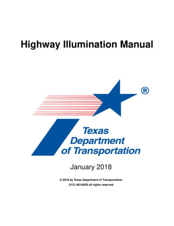
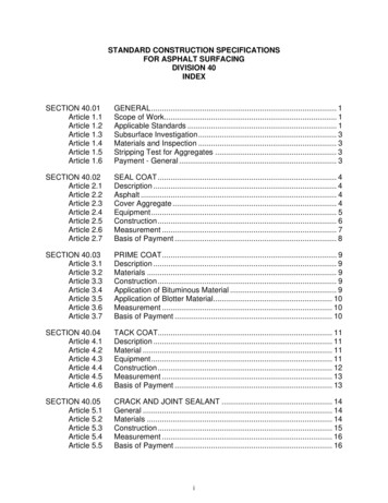
Lighting Design Guidelines2020Special ConsiderationsIlluminance calculations can be used to design curves and short steep hills. The atypical sectionof roadway should meet the same illuminance value as a straight section of roadway. With lightingcalculation software, the straight roadway illuminance value can be calculated at the same timeas the roadway luminance value. Curves typically require closer spacing of standards.Short steep hills may require closer spacing of standards.Some viaducts and flyovers may require alternative lighting solutions that limit the use of lightstandards.DESIGN EXAMPLESFigure 1: Typical Freeway Design, Plan ViewFigure 2: Alternative Flyover, Plan ViewLights located on the outside edge of theroad are typically 30 to 40 feet tall.Mid mast lights are typically 40 to 70 feettall and barrier mounted in the median.Figure 3: Alternative Flyover, Isometric View
Lighting Design Guidelines2020Complete interchange lighting provides relative uniform lighting within the limits of the interchange,including: main lanes, ramp terminals, frontage roads, or crossroad intersections.When to LightInterchange lighting is recommended when the local government agency is willing to pay anappreciable percentage of, or wholly finance, the lighting installation.Complete interchange lighting should be considered when the roadway is adjacent to a lighteddevelopment or roadway. Lights should be considered to improve nighttime visibility and minimizecontrast or shadows on the roadway to improve motorist navigation at night. Completeinterchange lighting may be justified per the following conditions: There are three or more successive interchanges with an average spacing of 1.5 miles.The adjacent area is substantially urban.The crossroad is lighted for at least 0.5 miles on each side of the interchange.Lighting CriteriaLighting levels will be considered as meeting the criteria if the calculated values are within tenpercent (10%) of the criteria or do not exceed the criteria by more than two times (2x).RoadwayTypeCompleteInterchangesFreeway AFreeway BAverageLuminance (cd/m2)AverageLuminance (cd/m2)0.60.4Average Uniformity(avg:min)Maximum VeilingLuminance Ratio(LVmax:Lavg)40.3Best Practices Mounting height: typically, 30 to 70 feet. Mid mast light standards (40 feet to 70 feet) are typically installed on large roadwayprojects; these light standards are typically median mounted to light the entire roadway. CDOT no longer installs high mast lights on new projects. Light Distribution: begin with a Type III distribution without any uplight (U0). Spacing: begin with a 5:1 spacing to mounting height ratio. Modify accordingly to meet lightingcriteria and other critical design issues. Light standards should follow the roadway through the interchange. When possible, a light standard should be placed in the gore area at off-ramps.Special Considerations Lights should be located on the inside of curves to minimize potential strikes from vehicles. Light standards present near residential neighborhoods present greater light trespasspotential. Low backlight (B0 through B2) and low glare ratings (G2 or less) should beconsidered to minimize light trespass.
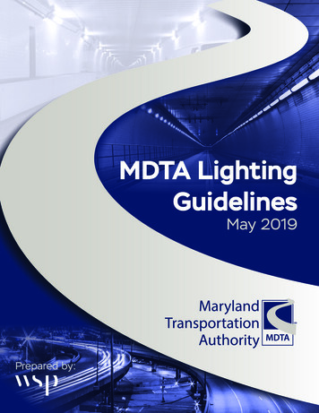
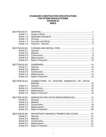
Lighting Design Guidelines2020DESIGN EXAMPLESFigure 4: Continuous Interchange, Plan ViewLights should be located on theinside of curves whenever possibleto minimize potential knockdowns.
Lighting Design Guidelines2020Partial interchange lighting provides illumination only on decision-making areas of roadwaysincluding: acceleration and deceleration lanes, ramp terminals, crossroads at frontage road orramp intersections, or areas of nighttime hazard.When to LightPartial interchange lighting is recommended at all locations where a non-continuously lightedhighway is adjacent to a lighted development or roadway. Partial interchange lighting is oftensufficient for lighting Freeway B highways adjacent to local developments.Partial interchange lighting should be considered for the following applications: Crossroad ramp terminals adjacent to a local development.Crossroad ramp terminals connecting any two of following roadway types: Intersections National highways State highwaysLighting CriteriaLighting levels will be considered as meeting the criteria if the calculated values are within tenpercent (10%) of the criteria or do not exceed the criteria by more than two times (2x).R1 (Concrete)Average Luminance(cd/m2)R3 (Asphalt)Average Luminance(cd/m2)Uniformity .40.64Local0.30.46Street ClassificationBest Practices Mounting height: typically, 25 to 40 feet. Light Distribution: begin with a Type II or Type III distribution without any uplight (U0). Fornarrow interchanges a Type II distribution may perform better. Spacing: begin with a 5:1 spacing to mounting height ratio. Modify accordingly to meet lightingcriteria and other critical design issues. Two to four light standards are typically installed along cross ramp terminalsSpecial Considerations Light standards present near residential neighborhoods present greater light trespasspotential. Low backlight (B0 or B1) and low glare ratings (G1) may be required to minimizelight trespass. Motorists are more likely to utilize the full length of a merge/diverge lane if the lane is lighted.Motorists are more inclined to immediately merge with traffic when the lane is not lighted.
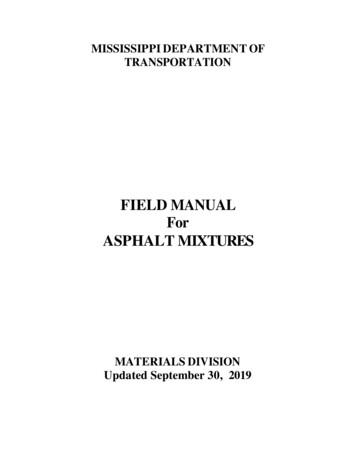
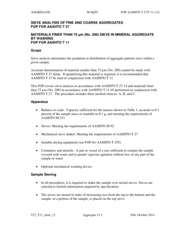
Lighting Design Guidelines2020DESIGN EXAMPLESFigure 5: Partial Interchange Lighting, Plan ViewA light should be located inthe gore area at off-ramps.Figure 6: Partial Interchange Lighted On-Ramp,Isometric ViewFigure 7: Partial Interchange Lighted Off-Ramp,Isometric View
Lighting Design Guidelines2020When to Light Underpasses do not require nighttime lighting if the adjacent roadway is not lighted. Underpasses on lighted roadways should be lighted to the same luminance as the roadway. Underpasses less than 80 feet in length, do not require supplemental lighting for daytimeadaptation. Underpasses between 80 feet and 410 feet in length, may require supplemental lighting fordaytime adaptation. Refer to Section 2.2.5 for more information.Lighting CriteriaLighting levels will be considered as meeting the criteria if the calculated values are within tenpercent (10%) of the criteria or do not exceed the criteria by more than two times (2x).StreetClassificationLuminanceRange (cd/m2)Avg. Uniformity(avg:min)Max. Uniformity(max:min)Max. VeilingLuminance Ratio(Lvmax/Lavg)Freeway Class A0.6460.3Freeway Class B0.4460.3Best Practices Luminaire optics or shielding should be carefully considered to avoid glare for motorists. Whenever possible the lights should be located above the shoulder on the outside edge ofthe roadway to minimize traffic impacts, due to lane closure, when the luminaire is maintained. Controls should be installed such that all underpass lights turn on and off at the same time.Special Considerations Most underpasses do not require lighting if the roadway light standards are adequately spacedand light the pavement beneath the underpass. For shorter underpasses, it may be possible to locate the roadway luminaires such thatsufficient light shines into the underpass without the bridge shadowing the roadway. For longer underpasses, it will be necessary to install wall or ceiling mounted luminaires. Use lighting calculation software to confirm whether adjacent streetlights sufficientlyilluminate the underpass or if additional underpass lights are needed. When the length to height ratio of an underpass exceeds approximately 6:1, it should beevaluated for the need for additional daylight illumination. Refer to Section 2.2.5 Tunnels foradditional information on short tunnels (underpasses with a length greater than 80 feet).DESIGN EXAMPLESFigure 8: Highway Underpass, Plan ViewFigure 9: Highway Underpass, Isometric View
Lighting Design Guidelines2020The term “tunnel” means an enclosure roadway for motor vehicle traffic with vehicle access limitedto portals, regardless of the type of structure or method of construction, that requires, based onthe owner’s determination, special design considerations that may include lighting, ventilation, fireprotection systems, and emergency egress capacity.Long tunnel structures with limited daylight penetration reduce motorists’ ability to adapt to lowerlight levels during the daytime, within the structure. For this reason, daytime and nighttime lightingshould be considered for any tunnel greater than 150 feet in length. Daytime and nighttime lightingis required for any tunnel greater than 410 feet in length.Refer to ANSI/IES RP-8-18 Chapter 14: Tunnel Lighting for information on how to design thelighting system for tunnels greater than 80 feet in length.When to LightThe type of tunnel lighting system upgrade is to be confirmed by the CDOT Project Manager. Existing lighting system upgrades: Minor upgrades do not need to follow these guidelines. Major upgrades may not need to follow these guidelines. Replacement of existing lighting system should follow these guidelines.Condition based replacements shall refer to the CDOT Bridge Inspection – National TunnelInspection Specification (NTIS) Inventory for information on the lighting system condition.Tunnel lighting rebates may justify a lighting upgrade.CriteriaTunnels have both daytime and nighttime lighting criteria; refer to ANSI/IES RP-8-18 Chapter 14:Tunnel Lighting for complete design criteria. Apply the Lseq method to determine the appropriatepavement luminance.Factors influencing lighting design criteria include: Bi-directional (undivided) or divided tunnel traffic direction. Confirm with the CDOT ProjectManager to see if a bi-directional lighting design is necessary for tunnel maintenance boreclosures.AASHTO Stopping Sight Distance varies by speed and roadway grade.Threshold zone lighting criteria is dependent on the: Tunnel portal solar orientation and surrounding geometry. Tunnel length, traffic volume, wall reflectance, daylight penetration, and visibility of theportal.The ratio between the average illuminances of the pavement and wall should not exceed 2.5:1.The luminaire shall be tested per, and meet, the following requirements:Tunnel Luminaire RequirementsCorrelated color temperature (CCT)4000K within the tunnelSalt spray test per ASTM B1171000 hours, minimumVibration rating per ANSI C136.313GIP rating per IEC 60598IP66Ambient operation temperature-40 C to 40 CPhotometric testingIES LM-79 and IES LM-80
Lighting Design Guidelines2020 Refer to NFPA 502 for emergency lighting considerations. Since NFPA has not been officiallyadopted by the State of Colorado, at this time, consult with the CDOT Project Manager todetermine which measures in NFPA 502 will be applied to the tunnel.Best Practices The tunnel preliminary design documents should include an evaluation of the existingconditions of the tunnel elements associated with the tunnel systems (luminaires, conduit,electrical wiring, lighting control system, etc.). On-site tunnel measurements should be taken per IES LM-71-14 Photometric Measurementof Tunnel Lighting Installations. Tunnel Maintenance and Operations should be consulted about: The tunnel cleaning schedule, The existing lighting system utility costs, and Desires for adding assets to the inventory. Avoid flicker and luminaire frequency between the range of 4 Hz to 11 Hz per the frequencyanalysis based on the luminaire spacing and design speed. The tunnel pavement and wall lighting levels should be calculated using AGi32 or equivalentlighting calculation software. Refer to the International Commission on Illumination (CIE) Guide for the Lighting of RoadTunnels and Underpasses, 2nd Edition for additional information on tunnel lighting systems.Special Considerations Luminaire maintenance is especially difficult in tunnels. Consul
the AASHTO Lighting Guide for additional information on roadway lighting design. This guideline should be used for all CDOT owned and maintained lighting installations. For lighting projects with CDOT oversight, the designer should f