Transcription
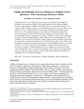
HOW TO SYNCHROAPRIL 2016HOW TO SYNCHROADD AERIAL PHOTO FROM BING Go to File Select Backgrounds, then click on “Bing Region List”, click on “Create Bing Region” button. Navigate or search to get to the location of your study. Pan and zoom to get the aerial view you would like in the window, then click on the “set reference” button.Click on the middle of the intersection and then a view of your synchro model will appear and ask you toselect the reference point in there as well. (If this is a new project you can put the Synchro reference point atX:0 Y:0). Then click OK Click the “Set Region Boundaries” button then click “Set 1st boundary point”. Click the red pin somewhere onthe lower left side of the aerial photo. Then “Set 2nd boundary point” on the upper right side of the aerialphoto. After you set the two boundary points it will shade the area in red, this will be the aerial photo viewthat will be downloaded into your Synchro model. Click the “Save Region” button, then “Close” button Now it will show a “Region 1” under the Bing Region List tab, click OK to exit the select backgrounds window. The aerial should appear in your Synchro model:1
HOW TO SYNCHROAPRIL 2016ADD LINKS Click on the add link button: Click on the screen at the approximate end points of your roads. It is okay to go outside of the aerial photo.After drawing two links that cross, the program will create a node at the point where the links intersect. Tomove the location of nodes (including end points), click this button:2
HOW TO SYNCHRO APRIL 2016Note that when the intersection node is selected, more buttons become available:Click hereMap WindowLane SettingsHCM 2010SettingsVolumeSettingsTiming SettingsSimulationSettingsPhasing Settings3SimTrafficAnimation
HOW TO SYNCHROAPRIL 2016LANE SETTINGSThis screen is used to enter in the lane arrangement on each approach of your intersection. At a minimum, enter thedata for the rows marked with the yellow star.Clicking in this area allows a drop down menu. Select thelane geometry for each traffic movement in this row.Default is 1900, change to 1750. See notes below.Enter storage length for any dedicated turn lanes. This isthe full-width distance of the turn lane.Ideal saturated flow should be 1750 for NDDOT projects. Go to Options Network Settings LanesFlow Rate (vphpl) [which shows up as “Ideal Satd. Flow” in the Lane Settings button] From NCHRP Report 599 page 6item 5 and also 2010 HCM page 18-76.If you are working on a proposed scenario to determine lengths of turn lanes, you may want to set the storage lengthas 1000 ft or leave it blank as a test run. Several test runs may be needed to fine tune the ideal storage lengths ofturn lanes before making the final recommendation in your traffic study.4
HOW TO SYNCHROAPRIL 2016MAP WINDOWGo back to the map window to verify if the lane geometry is correct. After you get your lane geometry entered itshould appear something like this:Click on the end node then clickthe lane settings button to set thespeed limit here, do this for allyour end nodes5
HOW TO SYNCHROAPRIL 2016VOLUME SETTINGSUse this screen to enter in your traffic volumes, truck percentages and peak hour factor.Enter the peak hour factor. Notethat it should be the same valuefor the entire row.Enter the hourly volume for each movement inthis rowEnter the percentage of heavy vehiclesSee notes belowFor the Peak Hour Factor (PHF) – if you have actual hourly counts, use may use that PHF to enter into this screen. Ifyou are using TMC’s use the default values of 0.88 for rural areas, 0.92 for urban.Link OD Volumes:Typically only change this at interchange ramps, to prevent off-ramp vehicles from turningonto the crossroad and then immediately turning back onto the interstate in the otherdirection. For example, if interstate runs E/W, go to the WB off-ramp intersection (a.k.a.north ramp), click “Link OD Volumes” for the NB lanes, go under the NB L column, and setthe “From EBL Weight” to zero. Then flip-flop these steps for the EB off-ramp intersection(a.k.a. south ramp). You may also want to use this when modeling J-Turn intersections – toprevent mainline thru vehicles from using the U-Turn areas.6
HOW TO SYNCHROAPRIL 2016TIMING SETTINGSSelect the type of intersection control here. Pretimed – traffic signal without detectors,typically downtown areasAct-Uncrd – traffic signal in “free” modeSemi Act-Uncrd – traffic signal with detectors onthe side street only, normally not used in NDActd-Coord – traffic signal with coordination withother nearby traffic signalsUnsig – stop signs on one or more approaches, skipto page 11RoundaboutNormally between 60 sec & 120 secOptions Network Settings Timings: Offset Style “TS2 – 1st Green” rather than “Begin of Green”. This greatlyimpacts time-space diagrams and coordination when one direction turnsgreen before the other! “TS2 – 1st Green” references the first coordinatedmovement to turn green, similar to controllers in the field. “Begin ofGreen” references when both coordinated movements are green.7
HOW TO SYNCHROAPRIL 2016TIMING SETTINGS (CONTINUED)Go to Options Phase Templates Edit Template Phases. This window will appear, edit these numbers so that thesignal phase numbers match with NDDOT practice. The correct numbers are shown below:Next, go to Options Phase Templates then select “Intersection to East-West” or “Intersection to North-South”,depending on your intersection. Then click OK.8
HOW TO SYNCHROAPRIL 2016PHASING SETTINGSAt a minimum, the yellow and all-red times should be entered on this screen.9
HOW TO SYNCHROAPRIL 2016SYNCHRO REPORTSDepending on the type of study you are doing, you may want to include some Synchro reports to provide moredetails of the timing and phasing as shown below:10
HOW TO SYNCHROAPRIL 2016SIGNING WINDOWIf unsignalized is selected as the control type, the button’s appearance will look like this:If your intersection is a two-waystop, be sure to set your majorroad approaches as “free”11
HOW TO SYNCHROAPRIL 2016SIMULATION SETTINGSNormally 12 ft, edit this if you arestudying a divided highway.This screen repeats some of the same information as the Lane Settings screen.Enter taper length here or go to Options Network Settings Simulation. Set to 100 ft rather than the default of25 ft. This makes the maps appear more realistic. In SimTraffic this allows vehicles to slide over into the turn lanewhen thru queues are backed-up all the way to the taper area.If your major road is a divided highway, enter the median width in the appropriate columns.Go to Options Maps Settings. These settings may be adjusted to control the appearance of the map view inSynchro. Check on the “Intersection Paths” to see the centerline of vehicle and pedestrian paths through theintersection. This may help you identify errors in the model.12
HOW TO SYNCHROAPRIL 2016SIMTRAFFIC ANIMATIONIf your Synchro file has been saved, a SimTraffic animation of your model can be created. Click this button:General Notes to Consider: In SimTraffic simulations, vehicles are not able to make two-stage left turns at unsignalized divided highwayintersections. The vehicles wait for a gap in both directions of traffic prior to turning (they won’t cross intothe median and wait in the median). However, the results in Synchro, do account for two-stage left turns ifthe median is wide enough to store a vehicle. See Version 7 user guide page 7-19. Typically use an average of 10 runs for SimTraffic simulation results. Synchro and SimTraffic queue lengths can be quite different. See Version 7 user guide page 23-13 and 7-27.For studies, typically use SimTraffic 95th percentile length or SimTraffic maximum length, whichever isshorter, rounded to 25ft increment. However, use Synchro (not SimTraffic) queue lengths for unsignalizeddivided highway intersections. Delete the simulation .HST files when finished with study. These have HUGE file sizes. Go to Options Intervals and Volumes: Change start time and duration if needed. Typical seeding 5minutes. Typical Duration [analysis period] 15 minutes. From 2010 HCM page 18-76 and Synchro Version 7user guide page 13-29. Switch “PHF Adjust” to “yes” rather than “no”. This incorporates the PHF values thatwere originally entered in Synchro. Go to Options Vehicle Parameters: Adjust the occurrence and length as appropriate for your situation.An example is below. Typically change Carpool1 and Carpool2 occurrence to zero.Watch the animation to see if there are any errors while coding the model in Synchro.13
HOW TO SYNCHROAPRIL 2016SIMTRAFFIC REPORTOnce you are satisfied with your Synchro/SimTraffic model, you are ready to generate a report.In SimTraffic, Go to File Create Report. The window below appears:Click this button to record additionalanimations. Typically we use an average of10 runs prior to generating reports.Queueing information isused to determine the turnlane geometryAt a minimum, a report should be generated showing the information shown in the window above. Other measuresof effectiveness (MOEs) can be generated as the author sees fit.14
Go to Options Intervals and Volumes: Change start time and duration if needed. Typical seeding 5 minutes. Typical Duration [analysis period] 15 minutes. From 2010 HCM page 18-76 and Synchro Version 7 user guide page 13-29. Switch "PHF Adjust" to "yes" rather than "no". This incorporates the PHF values that