Transcription
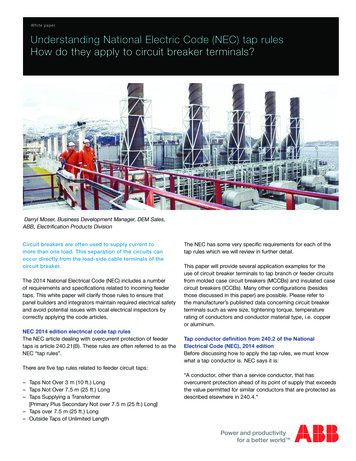
White paperUnderstanding National Electric Code (NEC) tap rulesHow do they apply to circuit breaker terminals?Darryl Moser, Business Development Manager, DEM Sales,ABB, Electrification Products DivisionCircuit breakers are often used to supply current tomore than one load. This separation of the circuits canoccur directly from the load-side cable terminals of thecircuit breaker.The 2014 National Electrical Code (NEC) includes a numberof requirements and specifications related to incoming feedertaps. This white paper will clarify those rules to ensure thatpanel builders and integrators maintain required electrical safetyand avoid potential issues with local electrical inspectors bycorrectly applying the code articles.NEC 2014 edition electrical code tap rulesThe NEC article dealing with overcurrent protection of feedertaps is article 240.21(B). These rules are often referred to as theNEC “tap rules”.The NEC has some very specific requirements for each of thetap rules which we will review in further detail.This paper will provide several application examples for theuse of circuit breaker terminals to tap branch or feeder circuitsfrom molded case circuit breakers (MCCBs) and insulated casecircuit breakers (ICCBs). Many other configurations (besidesthose discussed in this paper) are possible. Please refer tothe manufacturer’s published data concerning circuit breakerterminals such as wire size, tightening torque, temperaturerating of conductors and conductor material type, i.e. copperor aluminum.Tap conductor definition from 240.2 of the NationalElectrical Code (NEC), 2014 editionBefore discussing how to apply the tap rules, we must knowwhat a tap conductor is. NEC says it is:There are five tap rules related to feeder circuit taps: Taps Not Over 3 m (10 ft.) Long Taps Not Over 7.5 m (25 ft.) Long Taps Supplying a Transformer[Primary Plus Secondary Not over 7.5 m (25 ft.) Long] Taps over 7.5 m (25 ft.) Long Outside Taps of Unlimited Length“A conductor, other than a service conductor, that hasovercurrent protection ahead of its point of supply that exceedsthe value permitted for similar conductors that are protected asdescribed elsewhere in 240.4.”
The NEC tap ruleNext, let’s look at the specific NEC requirements for the twomost commonly used feeder tap rules:(1) Taps not over 3 m (10 ft.) long. If the length of the tapconductors does not exceed 3 m (10 ft.) and the tap conductorscomply with all of the following: The ampacity of the tap conductors isa. Not less than the combined calculated loads on thecircuits supplied by the tap conductors, andb. Not less than the rating of the equipment containing anovercurrent device(s) supplied by the tap conductors or notless than the rating of the overcurrent protective device at thetermination of the tap conductors.Exception to b: Where listed equipment, such as a surgeprotective device(s) [SPD(s)], is provided with specificinstructions on minimum conductor sizing, the ampacityof the tap conductors supplying that equipment shall bepermitted to be determined based on the manufacturer’sinstructions. The tap conductors do not extend beyond the switchboard,switchgear, panelboard, disconnecting means, or controldevices they supply. Except at the point of connection to the feeder, the tapconductors are enclosed in a raceway, which extendsfrom the tap to the enclosure of an enclosed switchboard,switchgear, a panelboard, or control devices, or to the backof an open switchboard. For field installations, if the tap conductors leave theenclosure or vault in which the tap is made, the ampacity ofthe tap conductors is not less than one-tenth of the rating ofthe overcurrent device protecting the feeder conductors.(2) Taps not over 7.5 m (25 ft.) long. Where the length of thetap conductors does not exceed 7.5 m (25 ft.) and the tapconductors comply with all the following: The ampacity of the tap conductors is not less than one-thirdof the rating of the overcurrent device protecting the feederconductors.Notes for application examples in this paper:1. All wire size ampacity references are for copperconductors.2. Conductor ampacities were taken from the 75 C columnof Table 310.16 in the 2014 Edition of the National ElectricalCode.3. Although conductors with insulation temperature ratingshigher than 75 C may be used, the ampacities may not exceed those shown in the 75 C temperature column.4. Circuit breakers are used in these examples but otherovercurrent protective devices such as fusible disconnectswitches may also be used.2 Understanding NEC Tap Rules ABB white paper The tap conductors terminate in a single circuit breaker or asingle set of fuses that limit the load to the ampacity of thetap conductors. This device shall be permitted to supply anynumber of additional overcurrent devices on its load side. The tap conductors are protected from physical damage bybeing enclosed in an approved raceway or by other approvedmeans.A highly simplified paraphrasing of the NEW tap rules has twomain points:1. A conductor rated a minimum of 10% of the ampacity ofa feeder conductor may be tapped from the feeder providedits length is not greater than 10 feet and it terminates in anappropriately sized overcurrent protective device.2. A conductor rated a minimum of 33% of the ampacity ofa feeder conductor may be tapped from the feeder providedits length is not greater than 25 feet and it terminates in anappropriately sized overcurrent protective device.Addressing the need for tap conductorsSome panel builders may use power distribution blocks to distributeelectrical power to multiple loads but many power distribution blockshave a low short circuit current rating (SCCR). Since their usage willlower the SCCR of the entire assembly, a better alternative solutionmay be to distribute branch circuits directly from the circuit breaker’sterminals. In order to do this, the circuit breaker terminal must haveprovisions to accept more than one cable per phase.Terminals for larger circuit breakers often have the ability to accepttwo or more conductors and some circuit breaker manufacturersmay have multi-conductor lugs available as an accessory for smallercircuit breakers. Normally, multi-conductor lugs on larger-framecircuit breakers are used to supply a single large load from a singlecircuit breaker, but this need not be the only application for theselugs. These multi-conductor lugs may also be used to split ordistribute the cables to feed more than one smaller load from thecircuit breaker by using the NEC tap rules.
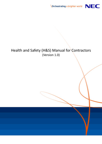
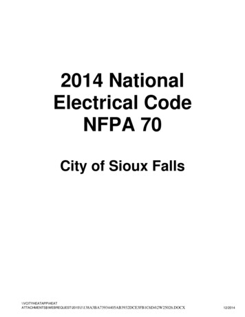
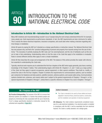
Short circuit current ratingsPower distribution blocks may serve the purpose of distributingelectrical circuits; their function is to provide a means to tap smallerconductors from a larger conductor, provided the tapping rules arefollowed. Conductors equal to the full ampacity of the circuit breakermust be extended to the power distribution block, and then properlysized taps may extend from the power distribution block to anovercurrent protective device.Even though the NEC tapping rules are followed, the short circuitcurrent rating (SCCR) of the circuit may be limited to a low value.Untested and unmarked power distribution blocks have a SCCR ofonly 10,000 amps which may severely limit the SCCR of anassembly. The use of multi-conductor terminals for circuit breakerscan overcome this limitation. Listed and approved multi-conductorcircuit breaker terminals take on the same SCCR as the circuitbreaker to which they are connected, allowing you to build a panelwithout having to reduce the SCCR. Also, by using the multiconductor terminal lugs and making the tap connection at the circuitbreaker terminals, the need for additional connection points iseliminated and panel space is saved.MisapplicationsIt is important to understand misapplication of the tap rules to avoiddesign or field installation errors; Figures 1-3 illustrate applicationexamples of feeder taps that are not in compliance with the NECrequirements.Figure 1 – Taps not permittedIn Figure 1, the 10 ft. tap rule is not in compliance with the NECbecause the #14 AWG wire is not at least 10% of the rating of theupstream overcurrent protective device.In this case, the #14 AWG wire is correctly sized based on theampacity of the Tmax XT1 circuit breaker to which it is feeding.However, the conductor is sized less than 10% of the rating of theTmax XT4 250A circuit breaker from which the tap originates, so itdoes not comply with the NEC tap rules. In order to make thisexample comply with code, the conductor must be less than 10 feetin length and the wire must be sized for at least 25 amps, therefore,changing the #14 AWG wire to a #10 AWG wire would bring theexample into compliance with the NEC tap rule.Figure 2 – Taps not permittedFigure 2 illustrates an example of the 25 ft. tap rule that is not incompliance. The conductor is within the 25 ft. limit allowed, but the#6 AWG wire is not sized to be at least 33% of the rating of theTmax XT4 250A circuit breaker. A #4 AWG wire would be theminimum wire size allowed in this example because it would berated for 85 amps and thus meet the 33% minimum ratingrequirement of the upstream overcurrent protective device.Figure 3 – Taps not permittedFigure 3 illustrates a Tmax XT4 frame circuit breaker with a 250 amptrip unit, with two circuit breakers tapped from it: one with a 10 ft.tap and the other a 25 ft. tap. In this example, the 10 ft. tap is incompliance but the 25 ft. tap is not because of the excessive wirelength. While multiple taps may be used, designers and installersmust be careful to meet all of the code requirements to be a validinstallation.In this example, the 10 ft. feeder tap is in compliance with the NECbecause the #10 AWG conductor is at least 10% of the rating of theupstream overcurrent protective device and the length does notexceed the 10 ft. limit. Unfortunately the #2 AWG conductor is not incompliance with the 25 ft. tap rule. Even though the conductor is atleast 33% of the rating of the upstream overcurrent protectivedevice, the wire length is 30 ft., exceeding the maximum lengthallowed, 25 ft.Often, an industrial control panel or NEC installation requires a circuitbreaker to be used as a main device, with lower ampacity circuitstapped from it. The following examples illustrate the correct usage oftaps derived directly from circuit breaker terminals.ABB white paper Understanding NEC Tap Rules 3
Figure 4 – Tmax XT4 circuit breakerFigure 4 illustrates use of a Tmax XT4 circuit breaker with a 250amp trip unit being tapped directly from the circuit breakerterminals. The 10 ft. tap rule states that a cable rated for at least10% of the rating of the upstream protective device must be used.In this example, we see that multiple taps are used coming from asingle circuit breaker as long as all of the taps comply with theNEC requirements.The 10 ft. taps are in compliance with the NEC because the #10AWG conductors are at least 10% of the rating of the upstreamovercurrent protective device and the lengths do not exceed the 10ft. limit. The multi-conductor cable lug of the Tmax XT4 is UL listedas a circuit breaker accessory and can accept up to six cables perphase within the range of #14 – 2 AWG. This allows the possibilityof having up to six taps coming from one circuit breaker. Note thata downstream circuit breaker with a lower rating may be used aslong as the conductor is still sized at a minimum of 25 amps.Figure 5 – Tmax T5 circuit breakerThe Tmax T5 circuit breaker has terminals available that can accepttwo wires per phase within the range of 3/0 to 250 kcmil. Figure 5illustrates a Tmax T5 circuit breaker with taps going to two TmaxXT3 200A circuit breakers. Taps are shown at full capacity foreach breaker.4 Understanding NEC Tap Rules ABB white paperFigure 6 – Tmax T6 circuit breakerThe Tmax T6 600A circuit breaker in Figure 6 has two smallerbreakers tapped from its terminals. The K6TH lug kit accepts twocables per phase, from 250-500 kcmils. By using a single 250kcmil conductor out as a tap up to 25 ft. in length, one can supplya circuit breaker up to 250 amps (A Tmax XT4 250A is shown inthe example to represent this.). By using a 500 kcmil conductor,which is the maximum wire size accepted by the K6TH lug kit, acircuit breaker up to 380 amps may be supplied. The adjustableelectronic trip unit settings of the Tmax T6 breakers makesthis possible.Figure 7 – Tmax T6 circuit breakerIn this example, the Tmax T6 600A circuit breaker has three tapsconnected to it. The K6TJ lug kit accepts wires within the range of#2/0-400kcmil. The minimum wire size (#2/0) is rated at 175 amps,so there is no problem meeting the 10% of the rating of the circuitbreaker requirement. Circuit breakers smaller than 175 amps mayalso be used, provided the cable is sized according to what thecable lugs can accept. Figure 7 shows the Tmax XT3 125A circuitbreaker tapped from the Tmax T6 600A circuit breaker, since thesmaller frame Tmax XT1 and XT2 cannot accept the #2/0conductor. The #2/0 is the smallest that can be installed in theK6TJ lug kit of the Tmax T6.
Figure 8 – Tmax T7 circuit breakerFigure 8 illustrates a Tmax T7 1200A circuit breaker used with three10 ft. taps. The KT7X1200-3 lug kit accepts four cables per phaseFigure 10 – Tmax T8 circuit breakerFigure 10 illustrates a Tmax T8 2500A circuit breaker used with four10 ft. taps. The K8TL lug kit accepts four cables per phase from#1/0 – 750 kcmil, to create a tap at 10% of the circuit breaker rating(250A) using a Tmax XT4 250A circuit breaker and a single 250kcmil cable per phase. Larger taps can also be created using largercables or multiple cables per phase. Another lug kit available for theTmax T8 circuit breaker, the K8TM, accepts six cables per phasefrom #1/0 – 750 kcmil, thereby expanding the options available forcreating taps.from 4/0-500kcmil. In this example, we demonstrate a range offrame sizes is demonstrated with circuit breaker ratings that can betapped using a single conductor from the Tmax T7 circuit breaker. Itshould be noted that lower ampere ratings of circuit breakers can beused, as long as the terminal lug will accept the proper conductorsize. In this example, a Tmax XT3 60A circuit breaker, or a TmaxXT4 rated as low as 25A, can be substituted in place of the 225Acircuit breaker.Figure 9 – Tmax T7 circuit breakerFigure 9 illustrates a Tmax T7 1000A circuit breaker used with two25 ft. taps. As evident in Figure 8, the KT7X1200-3 lug kit acceptsfour cables per phase from 4/0-500kcmil, but in this example we willshow that a tap can be more than one cable per phase. Here wedemonstrate a tap using three per phase #4/0 cables connected toa Tmax T6 600A circuit breaker and a single 500 kcmil conductorconnected to a Tmax T5 circuit breaker.Power distribution blocks are often used in industrial control panelsand NEC installations for tapping circuits; however, higher SCCRscan be achieved and panel space can be saved through the use ofmulti-conductor terminals on circuit breakers.SummaryFeeder rules apply to every industrial control panel. That makes itcritical that panel builders and integrators understand therequirements laid out in the NEC tap rules.This white paper provided both an explanation of these rules applyand a number of examples clarifying the rules. The correctapplication of these rules ensures proper protection of theequipment controlled by the panel, as well as the safety of thoseworking on or near the attached equipment.ABB white paper Understanding NEC Tap Rules 5
AppendixCircuit Breaker Cable LugsFrame sizeA1XT1XT2XT3A2XT4T5T6T7T81234Number of conductors per phase11161161161111111161223446Wire size14 AWG - 24 AWG - 114 AWG - 1/014 AWG – 2 AWG14 AWG - 1/014 AWG - 1/014 AWG – 2 AWG14 AWG - 1/04 AWG - 300 kcmil12 AWG – 2 AWG1 AWG – 300 kcmil300 - 350 kcmil14 AWG - 1/04 AWG - 300 kcmil250 - 350 kcmil14 AWG - 1/010 AWG - 250 kcmil250 - 350 kcmil12 AWG – 2 AWG250 kcmil - 500 kcmil3/0 - 250 kcmil250 - 500 kcmil2/0 - 400 kcmil4/0 - 500 kcmil1/0 - 750 kcmil1/0 - 750 kcmilCatalog number (set of 3PC2KXT4CUAL3-3PC2KXT4XCU-3PC1 3K6THK6TJKT7X1200-3K8TLK8TMFC Cu Terminals for copper cables onlyNot available for XT4X up to 150AFor use with the XT4 X version up to 150A only. Note XT4X from 175-250A uses the standard 250A CU lug.IEC rated onlyReferences NFPA 70, The National Electrical Code, 2014For more information please contact:Ted WodoslawskyABB Electrification Products8155 T&B BlvdMemphis, TN 38125Email: ted.s.wodoslawsky@us.abb.comwww.abb.comNote:The information contained in this document is for general information purposes only. While ABB strives to keep the information upto date and correct, it makes no representations or warranties ofany kind, express or implied, about the completeness, accuracy,reliability, suitability or availability with respect to the information,products, services, or related graphics contained in the documentfor any purpose. Any reliance placed on such information is therefore strictly at your own risk. ABB reserves the right to discontinueany product or service at any time. Copyright 2016 ABB Inc. All rights reserved.1SXU000243G0201 September 2016Tmax, Tmax XT and Formula Circuit Breakers
The 2014 National Electrical Code (NEC) includes a number of requirements and specifications related to incoming feeder taps. This white paper will clarify those rules to ensure that panel builders and integrators maintain required electrical safety and avoid potential issues with local electrical inspectors by correctly applying the code articles.