Transcription
Handicap RampDesign and ConstructionGuidelinesJanuary 2015Created June 2006Rev 10/30/2007Rev 11/6/2010Rev 10/5/2012Rev 1/31/2015Rockwell Collins Retiree VolunteersRCRVandWheelchair Ramp Assistance ProgramWRAPThese guidelines are provided as a service to interested parties; no liability is accepted by WRAP or RCRV in relation to its safety or applicability inindividual cases or in relation to its installation or adaptation for which appropriate medical, engineering or other professional services ought to beobtained. Permission is hereby given to reproduce these guidelines. WRAP and RCRV are voluntary organizations which provide assistance todisabled people utilizing the capabilities of retired technical volunteers, professional engineers, technicians, tradesmen and others.wrapiowa.orgCedar Rapids, Iowarcrv.orgCedar Rapids, Iowa
1/31/2015Handicap Ramp Design and Construction GuidelinesWheelchair Ramp Accessibility Program (WRAP) and Rockwell Collins Retiree Volunteers (RCRV)volunteers build handicap ramps for qualifying individuals and various service agencies in the CedarRapids, Iowa area. WRAP is primarily focused on providing handicap access for disabled people of limitedincome or resources. For those with adequate financial means, a contractor should be contracted for aramp. The handicap accessibility need is normally identified through the WRAP Intake Coordinator at 319369-7377 or through a service agency. Available funding depends on the individual qualifications andservice agency ability to assist. The cost of a WRAP ramp construction is basically for materials, while thevolunteers provide design and construction services at no cost. Each ramp design must be completed onan individual basis to accommodate the home owner, site, building permit requirements and individualneeds. As a result, a generic process has been defined which is then applied on an individual basis. Thisprocess flow includes the following steps: Handicap ramp need identified to WRAPFunding requestFunding availableIdentify ramp designerSurvey siteDesign ramp including ramp layout, material list, cut list, and costo Cut list is very important to avoid cutting the wrong boards and ending up short!Obtain approval from owner and neighborhood authorities (if required)Obtain building permit (if required)Ramp build scheduledMaterials ordered and DeliveredConstruction crew arrangedConstruction of rampNotify building department of ramp completionThe project requires a considerable amount of coordination and communication. The steps which usuallytake the longest calendar time to complete are: Site survey, ramp design, funding arrangement, andscheduling the materials and construction crews. Completion of a ramp project will typically be 4-6 weekslong even though the actual construction is only 1-2 days.The requirements that must be accommodated in the design of a handicapped-access ramp include:ConsiderationExplanationHome entryThe choice of door to which to run a ramp is influenced by the ease of accesswithin the home to the various doorways, the widths of the doorways, andwhether any platforms, stairs or porches already exist to which a ramp could beconnected.Space limitationsand obstaclesMany aspects of the design of a ramp are limited by the space available andobstacles (such as trees, buildings, and walkways) that affect where it can berun. Also, where is the lower end of the ramp to be terminated? The lower ramptermination must be on an even surface. This surface doesn’t need to be level,but should have a cross-slope of 1:48 or less.Building codesExplicit and implicit code requirements imposed by the city or county. Somecities require a signed permission slip from the owner stating that they wantWRAP to build handicap ramp on their property.1
1/31/2015StandardpracticesDesign standards that are commonly applied in the area. Also, although theyare not legal requirements for homeowners, the ADA Standards for AStandards/2010ADAstandards.htmestablish practices for commercial ramps that may be applicable or expected inhome construction. We also follow the guidelines established by the CedarRapids Building Department (attached).Specifics of thedisability andmeans ofmovementAlthough “standard” designs work well for many people, the specifics of how theramp will be used MAY affect the design. Examples include: If the disabled person can only be move with his/her legs extended, widerturning platforms are needed than can be accommodated by someone whocan move in a wheel chair with the feet lowered. If the disabled person uses a walker but is unstable on slopes, shallow stepsare probably preferable to a ramp. If the caretaker for the disabled person is weak, the ramp will need to beless steep than normal. Conversely, a powered chair or scooter can make asteeper-than-standard ramp quite acceptable. A design standard slope is 1:12; however several ramps have been builtwith 1:10 slope due to space limitations.Landing attachedto the houseThe landing next to the house is normally built on frost footings to prevent frostheaving-caused interference with the door in the winter. If the front stoop is seton frost footings, then the landing would normally be set on top of the stoop witha ledger board attached to the house. If the stoop is not on frost footings, thelanding can be set on posts set on frost footings. However, some city inspectorsdo allow the use of a ledger on the home and the other posts floating, which isusually much simpler. This can be built using a slight down-slope of the landingaway from the home (less steep than 1:48), which allows floating posts in thewinter from interfering with the storm door opening. This practice is sometimesallowed for mobile homes, in the same manner, which minimizes doorinterference issues with frost heaving and does not require frost footings.Verification of approach with the associated inspector is required.Expected usefullife of the rampA ramp with a longer expected useful life (more than 5 years?) or a tall structuremay need to be solidly attached to the home and built on frost free footings.Ramps expected to be used for five years or less float by setting on top of theground without footings. Some jurisdictions may require frost free footings. Thejustification for not using frost free footings is that they are temporary structures.NeighborhoodcovenantsRestrictions, especially affecting the aesthetic qualities of a ramp, may beimposed by non-governmental agencies. For example, many mobile-homeparks require that skirting be installed to hide the space underneath a ramp.Aestheticcompatibility withthe neighborhoodThe appearance of the ramp, especially the type of railing treatment (balusters,rails, etc.), should be chosen to ensure that a functional ramp is not viewed asan eyesore by neighbors.HomeownerpreferencesIf a ramp is needed in a home owned by someone other than the family of thedisabled person, the requirements of the owner may trump all otherconsiderations. Also, the home owner may desire to match some existingdecking or railing design.2
1/31/2015Client preferencesWhen designing a ramp that is not financed by the client or homeowner, tradeoffs must be made between functionality and cost. Some client preferences canbe accommodated with little impact on cost; others cannot. The ramp designermust deal with these tradeoffs to meet the client’s real needs while ensuring thatan agency intending to provide home access does not end up footing the bill fora great party deck.Access limitationsIt may be appropriate, particularly when designing a long ramp, to include stepsor other means for non-disabled people (such as mail carriers and deliverypeople) to reach the doorway without navigating the ramp.Some standard design practices have been developed which provide simplified, low cost construction totake place. These standards are the starting point of each design, and although variations can andsometimes must be made to these standards, adherence to them is desired. The Standards of RampDesign include: 3Construction with treated lumberIn general “medium” length lumber should be purchased for efficiency and stability (2x4 and 2x6boards 16’ or less and 4x4 posts 10’ or less). The designer may choose longer boards for aparticular design in order to optimize the design.Purchase standard 5/4x 6” deck board to minimize waste: 4-42” from a 14’ board and 2-60” from a10’ board.Assemble with screws (no bolts or nails except for joist hangers)Standard width 42” clearance between posts (allows 39” clearance between railings)Use three 2x6” stringers (see 90 and 180 Landing Detail drawings for ramp framing)Posts 4x4” and spacing not more than 8 feet (6’nominal)Posts to rest on 12”X12” piece of treated ¾” plywood for ground supportAssure lateral stability of posts (cross bracing at least one place in each direction as needed asshown in Figures 1 and 2)Stringers are attached to the posts with 3.5” screws where possible. Also use a high shear strengthscrew such as Spax, Torx or lag screw, 1/4 inch by 4 inch, at sill to home and at least one at everyload joint, typically 2x6's attached to 4x4s.Use of joist hangers required on all free stringers (not attached to 4x4) and use of hanger nails 15/8” required, not screws.Use 2x6 beams 49" long (48” minimum) or as required under stringers at every 4x4 post pairsupporting the stringers unless the stringers are resting on or very close to the ground. One beam isused if the stringer continues beyond the post. A beam is used on each side of the post if stringersjoin at the post. A center post is not needed if a beam is used unless two stringers are joined.In places where a free standing post does not have a beam cross member, 18.75" 2x6 blocks shouldbe place between the stringers close to the post to stabilize lateral movement of the post.Tall landings or ramps should have diagonal bracing between the posts to stabilize the structure.Use 5/4 x 6” decking boards on ramp surface and attach with 2.5” screws. (Shank on 2.5” extendsthrough the deck board and only binds the stringer.)An overhead clearance of 6'8" minimum is always required above all walking surfaces.Highly recommend use of a hand rail with finger hold routed out of 2x6. Ready-made vertical handrails may be purchased in only 8 ft length at lumber yards. Vertical hand rails routed from a raw 2x6can be obtained with any desired length. (Prior design using a 5/4x6 and 2x4 handrails raised someconcern with some building inspectors due to the long reach for a finger hold.)Railing height 36” above decking (height of 34-38” is allowed) unless 30" above ground where 36"minimum is required)Railing extension beyond the ramp ends varies by individual constraints and installation. Wherethere is no physical interference and the railings are used by the client, 12" extensions can be used.
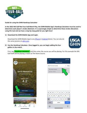
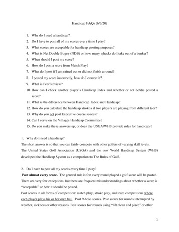
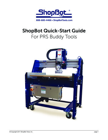
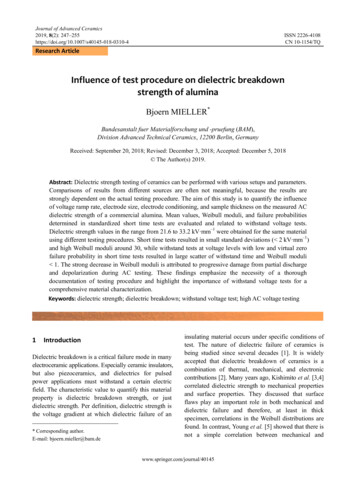
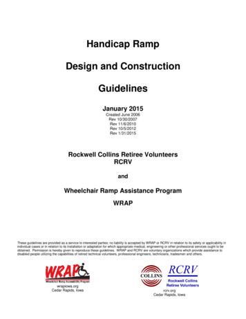
1/31/2015However, where an extension creates difficulty for entry to the ramp, no extension might be justified.Often the railings terminate at the ramp termination.Enclosed sides (Guards) are required for sections of the ramp over 30" above the ground or otherlower surface. The sides must be enclosed with openings less than 4".o If ramp is over 30” high, use two horizontal 5/4x6” deck boards or vertical balusters (must beenclosed with openings less than 4”).o Some building inspectors object to a “ladder” type of enclosed side that consists of horizontalboards.o Four balusters can be ripped from a 2x6 for less cost than the ready-made balusters ifacceptable to the client.Toe Board – use 2x4 mounted 3 ½” above deckingUse 5’x8’ landing for 180 degree turnaround (see Figure 1, 180 Landing Detail drawing)o When the handrail is attached to a post that extends above the handrail, a 2x4 spacer isplaced between the post and the handrail to allow room for a finger hold. It is recommendedthat the 2x4 extend all the way to the ground as shown in Figure 1.Use 5’x5’ landing (inside offset) for 90 degree turn (see Figure 2, 90 Landing Detail drawing)A 5’ long level ramp section or landing is required after each continuous 30’ of ramp length or 30” oframp rise.Vary joint locations of stringers, railing members and toe boards for improved stabilityHold downs are sometimes required by local codes for wind loading. If required, one approach is touse 12-15” earthen hold downs (not dog-screw types) and cable from the eyelet to each section ofthe ramp. If the ramp is constructed over concrete, Tapcon screws holding metal plates can beused.An End Post Bracket is used to support the two end posts. This is fabricated from steel angle ironand plates as shown in the drawing in Figures 3 and 4, Handicap Ramp Termination drawingsA Ramp End Assembly is constructed from wood as shown in the drawings. This may either befabricated in advance or on site. The structure is screwed together from the bottom and attached tothe end posts with screws through the 2x4 toe board. A ¾” plywood base may be required underthe End Post Bracket and Ramp End Assembly to stabilize it on the ground. (see Figures 3 and 4,Handicap Ramp Termination drawings and Appendix A.) It is very desirable to terminate the ramp atan even surface so the tapered edge of the last deck board is tight against the ground. Whenterminating on uneven concrete, consider fastening the end board down with a Tapcon screw intothe concrete.Building codes are followed (see Figure 5, Cedar Rapids building code handout)Each installation requires site assessment and a specific design developedA great deal of time may be saved at the construction site by developing an accurate bill of materialsin advance.It is also very helpful to create a “cut list” which includes each board and its length, and where theboard will be used in the construction.Figures:1. 180 Landing Detail2. 90 Landing Detail3. Ramp Bottom Termination Assembly4. Ramp Bottom Termination Detail5. Cedar Rapids Building Code Handout6-10. Photos of typical rampsAppendices:A. Ramp Termination Construction GuidelinesB. Vertical Handrail Construction GuidelinesC. Stair Design GuidelinesD. Skirting Installation GuidelinesE. Jigs used in construction4A1-5. Stringer CutsA6-12. Terminal decking constructionB1. Handrail ProfileC1. Stair Design ExampleD1-5. SkirtingE1-5. Jig photos
2x4 spacers forhand railingbeamsRamp framingbeam2x4 spacer oninside-down-railingpostsCompleted ramp2x6 cross bracebeam67routed groove in 2x6423530.5362x4 toe board5/4x6 flooring963.52x6 stringer4x4 post12x12x3/4AC2/GC plywood base60sides with less than4" openings requiredif over 30"Post detail1:12 typical slope2x4 spacer forhand railingbeams60 decking18 boards reqFrame top view6 to 8 ft typicalRamp side viewRCRVFigure 1. Handicap Ramp180 Landing Detailrev 10/30/07rev 11/6/10rev 1/31/15
2x6 cross bracescenter postno beambeamno center postno 2x6 cross bracesCompleted RampRamp Framing6760 decking11 boards req4257.549beamRamp top view6 to 8 fttypical18.75cross brace 2x6Ramp side viewRCRVrev 10/30/0742Figure 2. Handicap Ramp rev 11/6/10rev 4/7/1290 Landing Detail rev 1/13/15
Attach stringer to post with screwsEnd Ramp Assemblybottom viewAttach End RampAssembly topost with screwsStringer and Post LayoutEnd Post BracketAttach post toEnd Post Bracketwith screwsRCRV / WRAPCompleted RampFigure 3. Handicap RampRamp Bottom Terminationrev 11/6/10rev 1/31/15
3.5 x9 x 0.125 steel plate9weld all edges1.5 x 1.5 x 0.125 angle iron1.51.51.542 1/849 1/8End Post Bracket20.75305/4 x 6 x 42deck boardstapered edgeon last board0.56.257/324 holes2x4 toe board922 min1.75 minimum3.53.5 x 9 x 0.125 steel plate (2)tapered 2x stringer 23"end post bracket27.5End Ramp AssemblyRCRV / WRAPFigure 4. Handicap RampRamp Bottom Terminationrev 11/6/10rev 1/31/15
1/31/2015Photos of typical rampsFigures 6 through 10 are photos of a typical ramp constructed using the design standardsdescribed above. The ramp is 33 feet long with a 180 landing.Figure 6. Ramp frame with 180 landing.Notice cross bracingFigure 8. Stringers into Ramp end postassembly. Notice cross braces.Figure 10. Completed ramp10Figure 7. Ramp frameFigure 9. Ramp frame. Notice crossbraces.
1/31/2015Appendix A. Ramp Termination Construction GuidelinesTermination of a ramp has special issues because it is so close to the ground. Often digging is not possible andwhen it is, it is difficult and time consuming. WRAP has developed several techniques to construct solid rampterminations that are described here. The ramp usually consists of a Termination Assembly and the End Stringersthat extend from the fully above ground ramp structure to the Termination Assembly. Both the End Stringers andTermination Assembly construction considerations are discussed here.End Stringer ConstructionWhen terminating the ramp on concrete or on a hard reasonably level surface that requires little or no digging, thestringers approaching the ramp termination must be tapered to rest on the ground. In other cases it may be desiredto have the ramp butt into the edge of a concrete or other hard surface so there is a smooth level transition to theramp without using a tapered deck board. Occasionally the ground is sloping away from the ramp at the plannedramp termination and will require a very thin taper on the stringer which may be very weak. In this case the stringershould be dug in with little or no taper.Figure A1 shows a common situation where the termination assembly is set on concrete or reasonably level groundand the stringer must be tapered to lay on the ground. The 2x6 stringer is set exactly 5.5" above its final restingplace and a line is drawn on the stringer that is 5.5" above the ground. When marking the cut line, the stringershould be positioned so that the bottom of the stringer is exactly at the level planned for the top of the stringer whenit is installed. One end of the stringer is set on the previously installed up-ramp stringer and the other end of thestringer is shimmed so that a projection of the bottom surface of the stringer intersects the ground 2"-3" from theplanned end of ramp. Figure A2 shows the final installation using a tapered end deck board.If the ramp will end by butting up to a concrete, dirt, or other solid surface, the ramp can end with a whole deckboard rather than the tapered end board. The ground approaching the solid surface edge must be an inch below thatsurface so the last deck board can be flush. Marking the cut line is similar except the stringer is set on top of a deckboard at one end and shimmed so the bottom surface of the stringer projects to the top edge of the solid surface asshown in Figure A3. The cut line must be marked 6 5/8" above ground level to account for the deck boardthickness.If the ground has a downward slope at the ramp end as shown in Figure A4, the required taper on the stringer leavesinsufficient thickness to support the ramp. The stringers could be partially dug in to lower the ground level underthe stringers and use the tapering method of Figure A1. A better solution is often to use a full width 2x6 extendedall the way to end of the ramp as shown in Figure A5 where a trench is dug for the stringers. The end bracket is stillused to provide lateral support for the end posts.A1
Installed postand stringer1.75 minimumcut lineEnd of rampEnd of stringer27.5termination assembly5.5groundFigure A1. End stringer cut line markingdeckingEnd of rampEnd of stringerTapered deck board27.5termination assemblygroundFigure A2. End stringer installed on level groundInstalled post, stringerand deck board1.75 minimumEnd of rampcut lineend deck boardconcrete,dirt, or othersolid surface27.5termination assembly6 5/8groundFigure A3. Ramp butts into concrete or dirtcut lineInstalled postand stringerEnd of rampEnd of stringer5.527.5termination assemblygroundFigure A4. End stringer cut line marking on down slope groundInstalled post,stringer and deckEnd of rampwith endbracketEnd deck board flush with groundground before excavationFigure A5. Uncut end stringer installed on down slope ground
1/31/2015Termination Assembly ConstructionThis is a general approach to construction and installation of the termination assembly (TA). This assembly fitsbetween the steel end bracket (last 4x4 posts) and the end of the ramp. The use of the end bracket and this assemblyallows the ramp to terminate on hard surfaces like concrete without digging holes or using Tapcon screws.1. Decide length of termination desired. Standard design uses 5 deck boards and is about 27 ½" long. Standard42" deck boards are used and the last board is typically tapered to minimize the abrupt start up the ramp.a. Options including using less than 5 boards, especially if ending on a slight “upslope.”b. The TA determines where the steel end bracket, last two 4x4 posts and ends of final stringer willbe.c. If the surface just before the termination is soft and can be excavated, a full thickness deck boardshould be considered rather than a tapered board.2. Install the steel end bracket and final 4x4 posts. This step finalizes the final stringer lengths, and verifiesthe length of TA required. NOTE: If the position of the end bracket has been confirmed, its installation canwait until the TA is completed.3. Locate a flat area for assembly and gather the needed boards: 4-standard 42" deck boards, 1-tapered 42"wide deck board, and 2-2x4x30" toe boards with 5 degree ends.4. Construct the Termination Assembly UPSIDE DOWN.Figure A6. Upside down terminal decking constructiona. Place 2 toe boards 42" apart with 5 degree ends proper and mark 4" from one end on each.b. Place a deck board on the toe boards at the 4" line just marked. NOTE: I usually place all 4 regulardeck boards on the two toe boards just to stabilize things.c. Use a framing square to line up the deck board at 90 degrees to one toe board and attach with two2 ½"screws.d. Measure the distance between the outsides of the two toe boards and make this measurement 42".This is IMPORTANT to make sure that this assembly will fit between the two 4x4 end posts andend bracket “wings.”e. Use framing square to line up the second toe board at 90 degrees to this first deck board with thedeck board at the 4" line. Attach with 2 screws.f. IMPORTANT measure to make sure the toe boards are parallel and 42" apart (outside tooutside) at both ends, AND recheck that first deck board is still perpendicular to both toe boards.g. Attach remaining 3 standard deck boards one at a time by snugging them up to the prior one (don’tuse spacers) and using 2 screws at each end of each. When these 4 deck boards are screwed to theA3
1/31/20155.6.7.8.9.toe boards, there should be about 3-4" of each toe board remaining for attachment of the tapereddeck board.h. Attach the tapered deck board using two screws on each end. Place the sawn, tapered side down (itwill be showing when the assembly is placed right-side up). It is IMPORTANT to only use screwswhere the tapered board is full thickness (about the first 2 inches or so). This prevents the screwsfrom “lifting” the board’s edge. NOTE: It is sometimes helpful to predrill the tapered board toprevent splitting from the screws.Install end bracket and 4x4 posts are if not yet installed (#2 above). It is IMPORTANT to install the 4x4posts vertically, but equally IMPORTANT, they cannot extend into the 42" wide space between the twobracket “wings”. Note: the end bracket must horizontally aligned with the ground at the termination, whichmay not be level. Therefore the vertical posts may not be 90 from the bracket.a. 4x4 posts should be long enough to be 35" above the tops of the stingers. Attach end bracket toposts with 2 ½" screws.b. See other information on cutting the stringers to fit. Their ends should be 1 ¾" height minimum.c. Attach outside stingers to 4x4 posts using 3 ½" screws. The center stringer should be resting on thesteel angle iron.d. Install a standard 42" deck board across the ends of the stringers with its edge even with the angleiron.Place TA in position to verify that it fits into space properly and its tapered board end will fit “flush” tosurface at ramp’s end. This also verifies that the assembly will fit between the two 4x4 posts.Construct “wedges” to be used as extension of stringer to support deck boards.a. Construct each wedge as if all three are different (they most often are not the same size).b. Measure the height for one “outer” wedge at the angle iron bracket. Then measure the expectedheight 23" toward the end from the bracket (this is often 0" (zero) for concrete surfaces).c. Construct a wedge (triangular) with the dimensions from b. above and place it in place to see howit fits. Adjust as necessary.d. Install first wedge with one screw to simply hold it in place for now.e. Repeat this process for the other outer wedge, test it, and when the fit is right, install with onescrew.f. Measure the height of the center wedge like b. above, construct the wedge and test it. It isIMPORTANT that this wedge supports the center of the deck boards adjust if necessary.g. When all 3 wedges fit properly, attach the outer wedges with more screws. The center wedge canbe screw both from the top or bottom, being careful not to go too deep if screwing fromunderneath.Install completed TA at the end of the ramp. It is IMPORTANT that this assembly does not “lift” thetapered board end on one side or the other. The tapered board edge MUST lay against the hard/concretesurface. This can be tested by standing on the upper part of the TA and making sure the end stays down.a. Sometimes adjusting is necessary to keep the TA end in contact with the concrete.b. Rarely, balusters made of 2x4s can be placed between the railing and the toe boards at the end ofthe TA toe boards “pushing” them down to hold the TA edge tight against the concrete.Attach TA toe boards with two 3 ½" screws. IMPORTANT-This should be done while standing on thetapered board to assist holding it down during attachment.a. The regular ramp toe boards rest on top of the TA toe boards and therefore must be attached afterthe TA.NOTE: The termination bracket was widened by 1/8” in 2015 so the dimension between the two bracket wings increased from42 to 42 1/8”. If constructing a TA from an older bracket, use a 41 7/8” width instead of the new, 42” width of the TA.A4
1/31/2015Figure A8. Cut 3 wedges for TAstringers.Figure A9. Completed TA - upsidedown.Figure A11. End post bracketFigure 12. TA inserted into end postbracketFigure A7. Screw deck boards to toeboards while upside down.Figure A10. Completed TA - rightside up.A5
1/31/2015Appendix B. Vertical Handrail Construction GuidelinesTools required: Two routers with 1/2" collets.Freud 99-444 or equivalent 1-3/16" (Dia.) Handrail Bit.Freud 34-124 3/8" or 34-126 1/2" or equivalent Radius Rounding Over Bit.Hand held electric planner (Optional).Random orbit sander.80 grit sanding disksEquipment to support the 2x6 such as a Workmate Construction process (see figure B1):1. Select the best 2x6 material before the saw guy starts cutting them up. Selection should be madebased in lack of defects such as knots and slits along one edge.2. Inspect the material for any foreign objects that may damage the cutting tools.3. Plane the top edge using a hand held electric plane (Optional).4. Plane the sides if needed (Optional).5. Route the finger hold along ONE side with the bit adjusted to place the center of the radius 1”below the top. It is best to do this in two passes.6. Route the round over along both of the top edges. Note: if the bearing on the bit falls into thefinger hold it will be necessary to run the bearing on the top of the 2x6 or route the round overbefore the finger hold. Another option is to route the round over first.7. Sand the top and sides to provide a smooth splinter free surface.Note: An acceptable alternative is to route a 3/4" 'V' 1" down and 1/2" deep on the 2x6 and then sand thetop and bottom edges but that is not the WRAP standard.Figure B1. Handrail profileB1
REQUIREMENTS:Rise less than or equal to 7 3/4"Tread greater than or equal to 10"Variation in Rise or Tread less than 3/8"Some Building Departments allow open stairs(No deck board on the Rise)LandingAttach Stair stringersto landing withhangers and/or4x4 posts.A header board onthe landing may berequired.Rise 1.125HeightRiseTread-1.1252x3 - 2x12 stringers12 - 5/4x6 deck boards 1.125 x 5.5"Tread 11"Height 33.5"Steps 5Tread12TreadstringerRise Height / Steps 33.5/5 6.7" 6 11/16"1.125RiseRiseRise - 1.125GroundRun (Steps - 1) x TreadAppendix C. Stair Design GuidelinesFigure C1. Stair design example1/31/2015
1/31/2015Appendix D. Skirting Installation GuidelinesD1. IntroductionSkirting is added to ramps, typically only in mobile homes which have a requirement specified by themobile home court owners. Skirting prevents various animals from camping underneath ramps andprovides a consistent look to the home and ramp. Aesthetically, the ramp and home would have a finishedand consistent look throughout the property.To give the skirting a smooth and consistent look from the home throughout the entire ramp, filling ingaps as described in the Installation Guide is necessary. Filling in gaps between 4x4’s and from platformsto decks enables a smooth look to the skirting and enables installation to complete with much more ease.Vinyl skirting pieces are easily cut with a circular saw, and portable saws are especially handy. A vinylsaw blade can be used, or simply reverse the standard wood cutting blade in the saw for even, not tooaggressive cuts. Old (reused) skirting pieces become much more brittle and sometimes cannot be cutwithout chipping and breaking off pieces and must be discarded.Sheet metal screws are normally used for attachment of vinyl pieces to the ramp, and hex heads areconvenient. Using nails for attachment can
may need to be solidly attached to the home and built on frost free footings. Ramps expected to be used for five years or less float by setting on top of the ground without footings. Some jurisdictions may require frost free footings. The justification for not using frost free footings is that they are temporary structures. Neighborhood covenants