Transcription
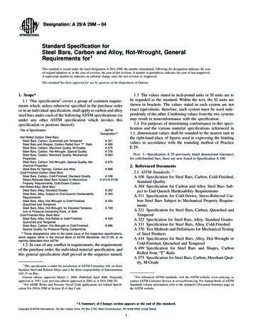
iSPAN , A Light Steel Floor SystemD.M. Fox1, R.M. Schuster2, and M.R. Strickland3AbstractDescribed in this paper is a cold-formed steel floor system called ‘iSPAN’. Thesystem is comprised of multi-functional components including the iSPAN FloorJoist, which is fabricated by fastening two cold-formed chord elements to a flatweb element resulting in a visual I-type cold-formed steel section. This makes itpossible to create a section where the chord elements can be of a different steelthickness with respect to the web element, resulting in a most structurallyefficient cross section. The section has lip-reinforced web openings along thejoist length to accommodate the usual service elements. Extensive tests havebeen carried out to substantiate the structural performance in comparison to thecalculated values for flexure, shear, and web crippling. It can be concluded thatthe iSPAN Floor System has one of the highest mass to strength ratios in theindustry.IntroductionThe iSPAN Floor System, shown in Figure 1, has been developed in response tothe need for a simple, long spanning floor system with superior fire resistanceand acoustic ratings. It is comprised of multi-functional components including1Product Developer, iSPAN, Richmond Hill, Ontario, CanadaProfessor Emeritus of Structural Engineering and Director of the CanadianCold-Formed Steel Research Group, Department of Civil Engineering,University of Waterloo, Waterloo, Canada3President, Paradigm Focus Product Development Inc., Richmond Hill, Ontario,Canada2
the iSPAN Floor Joist, End Connector, Snap-In Bridging, and Blocking. It isthe first light weight floor system that is able to achieve a 1 hour Fire ResistanceRating (FRR) with only one layer of 5/8in. gypsum board and plywood or OSBsheathing while maintaining a Sound Transmission Coefficient (STC) of 50when constructed as per UL L575 / ULC M513.¾” OSB or PlywoodiSPAN JoistEnd ConnectorBlockingBridgingFigure 1 - iSPAN Floor SystemThe joist, shown in Figure 2(a), is comprised of a top and bottom chord rivetedto a web element, allowing for structural optimization of the joist. Lipreinforced utility holes are provided at regular intervals in the web along themember to facilitate service installation for follow-up trades. Shown in Figure2(b) is an integrated end connector that connects the joist to a rim joist as well asstiffens the web element at bearing locations. Furthermore, the end connector isable to extend past the end of the joist, accommodating on-site tolerances. Thewings of the chords have bridging holes that accept iSPAN Snap-In Bridging.Top ChordWebUtility HoleEnd Connectorextends past web,elongating joistBottom Chord(a) iSPAN Joist(b) Integrated End ConnectorFigure 2 - iSPAN Floor Joist
iSPAN Bridging, shown in Figure 3, snaps into the wings of the chord elements.As well as providing lateral stability of the joist, the bridging allows for properjoist alignment without the need of a measuring tape or a square after properinstallation of the initial joist in a floor. The bridging elements also provide asurface to attach iSPAN Blocking. The blocking, shown in Figure 3, providesadditional lateral stability and resistance against racking while maintaining aservice corridor with the same utility holes as found on the joist web.iSPANBlockingiSPAN BridgingFigure 3 - iSPAN Bridging and BlockingiSPAN Joist TestsPresented in the following sections is an overview of the tests performed on thejoist along with appropriate comparisons based on the 2001 North AmericanSpecification for the Design of Cold Formed Steel Structural Members (hereinreferred to as the NAS) (NAS, 2002). All tests were carried out in RichmondHill, Canada. All tested joists were fabricated from ASTM A653 steel fromwhich coupon tests were taken, the results of which are shown in Table 1.Table 1 - Material si)Fu(ksi)160.057057.572.5 [500]180.047558.568.0Flexural TestsFlexural tests were performed on 12in. deep joist, the dimensional properties ofwhich are shown in Table 2 and the test setup is shown in Figure 4. The shear
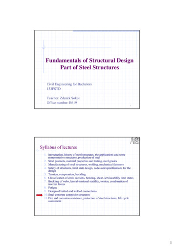
spans of the joists were reinforced to prevent preliminary failure and the joistswere fully supported laterally during loading.In each test, the total load, Pt was electronically recorded and the results of thetests are summarised in Table 3. In all tests, the joists failed away from thelocation of the lip-reinforced hole by chord/web local buckling, as shown inFigure 5. Failure always occurred between rivets. Neither rivet failure norlocalized failure of the material around the rivets was ever observed.The NAS was used to calculate the nominal flexural capacities of the joists, Pc,with modified stiffened and unstiffened plate buckling coefficients of 2.50 and0.30. Test to calculated ratios, Pt/Pc, for the specimens were on average equal toor greater than 1.0 and are shown in Table 3.Table 2 - Flexural Specimen .0161.751.016Table 3 - Comparison of Flexural Test Results to 7.698.129.1010.1Pt/Pc1.021.021.040.99
FCWPL’t2PbL’Dt1L(b) Joist Cross Section(a) Test SetupFigure 4 - Test SetupFigure 5 - Photograph of Typical Flexural Failure of iSPAN Joist
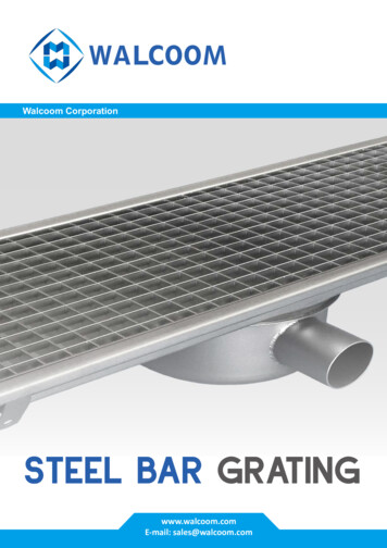
Shear StrengthThe shear strength of the joist web was established using the test setup shown inFigure 4. The constant moment region of the joist was reinforced to prevent apremature failure and the joists were fully supported laterally during loading.Joists with and without lip-reinforced holes were tested, the properties of whichare shown in Table 4 and Table 5, respectively. The web was fully reinforcedalong the length of the joist except within the shear panel, a.In each test, the total load, Pt, and the mid-span deflection were electronicallyrecorded, the results of which are shown in Table 6 and Table 7 for joists withand without holes, respectively. Each test failed in diagonal shear buckling,originating from the corners of the shear panel inside the chord elements, asshown in Figure 6 and Figure 7 for specimens with and without holes,respectively. The NAS was used to calculate the nominal shear capacity of theweb, the results of which are included in Table 6 and Table 7 as Pc. As a resultof the shear buckling being confined between the wings of the chords, theeffective height of the web, h, can be assumed to be the distance between thewings of the chords, reducing the web slenderness ratio relative to a C-section ofsimilar overall depth. As such, Pc was calculated on the basis of the web area,slenderness ratio, and aspect ratio as follows:Web Area, Aw [D 2t1 ]t 2(1)Slenderness Ratio, h t [D 2C ] t 2(2)Aspect Ratio, a h a [D 2C ](3)The tested web shear strength of the ranged from 13% to 96% for webs withholes and 63% to 309% for webs without holes greater than the predictedcapacity calculated as per the NAS.The shear buckling equations found in the NAS were calibrated from test resultsof C-sections. Due to the profile of the C-section, the support conditions alongthe edges of the web tend to behave in a simply supported manner with a shearbuckling coefficient, kv, of 5.34, as shown in Figure 8(a). In the iSPAN FloorJoist, the web is held in place at the top and bottom by the chords. This providesa rotationally stiffer edge support, as shown in Figure 8(b), and is supported bythe fact that no web distortion is observed within the chords during shear failure.The theoretical shear buckling coefficient, kv, for fixed edges is 8.98.
However, setting kv equal to 8.98 and calculating the shear capacities, shown asPc2 in Table 7, is still a conservative approach for the specimens without holes.The tested capacities ranged from 3% to 172% greater than the calculatedcapacities, Pc2. Further work is required to fully develop a suitable designequation.Table 4 - Shear Specimen Dimensions WITH Utility Holest2L’(in.)ShearPanel,a 1.0SH3122.01.75SH4122.01.75SH5122.0SH612SH712Table 5 - Shear Specimen Dimensions WITHOUT Utility Holes1.0t116t21825.0ShearPanel,a (in)72
Table 6 - Results of shear tests on specimens WITH 4710.59.221.14SH71793.5310.85.541.96Table 7 - Results of shear tests on specimens WITHOUT 2632.0415.73.844.095.772.72
Figure 6 - Typical Shear Failure WITH HolesFigure 7 - Typical Shear Failure WITHOUT Holes
Figure 8 - Web Support Conditions for (a) C-section, and (b) iSPAN JoistWeb Crippling CapacitySome preliminary web crippling tests have been carried out considering the fourtypical loading cases contained in the NAS. Early indications show that thebasic web crippling equation in the NAS can be applied to the joist with newlyestablished coefficients based on test results.Floor System ComparisonsComparison TestsThe primary objective of the comparison tests was to establish the structuralcapacity of an iSPAN Floor System in comparison with an equivalent typicalC-section floor system. The overall dimensions of both floor systems were thesame, i.e., 22 ft x 4 ft. In the case of the C-section floor, four 22 ft long 16gauge joists were spaced at 16 in. on center while the iSPAN Floor System wasmade up of three 22 ft long 18 gauge joist sections spaced at 24 in. on center. Inboth cases, ASTM A653 (Grade 50) steel and 5/8 in. OSB sub flooring wasused. The OSB sub floor was attached with 1 1/2 in. long # 10 self-drillingscrews, spaced at 6 in. o.c. along each joist length.
In each case, the floor specimens were positioned in the test frame as shown inFigure 9 and Figure 10. After proper alignment of the floor specimens in thetest frame, a string-pot deflection transducer was attached at centre span torecord the deflections during loading. A line load was then applied at the centreof the 22 ft span until failure. Each steel assembly, without the OSB subfloor,was also weighed to establish the proper strength to weight ratio. In both cases,failure was experienced by local buckling in the compression flanges, as shownin Figure 11 and Figure 12.Shown in Figure 13 are the load deflection curves for each floor system tested.The weight of the C-section floor was 352 lbs and the failure load was 6624 lbs,resulting in a strength to weight ratio of 6,624/352 18.8. For the iSPAN floor,the failure load was 10,724 lb and the weight was 366 lb, which resulted in astrength to weight ratio of 10724/366 29.3.As well, it can be observed that the iSPAN floor has an increased stiffness incomparison to the C-section floor. In fact, at both the L/360 and L/480deflection levels (0.73in. and 0.55in., respectively) the iSPAN Floor Systemcarried 25% more load than the C-section floor at the same deflection.Figure 9 C-section Floor in Test Frame
Figure 10 - iSPAN Floor System in Test FrameFigure 11 Photograph of failure in C-section Floor
Figure 12 - Photograph of failure in iSPAN Floor SystemFigure 13 - Load Displacement Plots of Assembly Tests
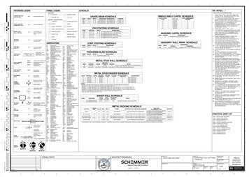
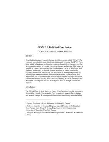
Weight to Span ComparisonTo extend the comparison of the test assemblies, an analysis was performed todetermine the weight savings that could be achieved by using the iSPAN FloorSystem with respect to typical C-section floor system.For the iSPAN Floor System, joist depths of 10in. to 16in. were assumed, using20ga. (0.036in.) to 14 ga. (0.075in.) steel thicknesses. The flange width (F),chord depth (C), and the wing length (W) were kept constant at 2.0in., 1.75in.,and 1.0in., respectively. The yield strength of the steel in all cases was 50ksi.For the C-section floor, typical configurations offered by current manufacturerswere used. Joists depths ranged between 10in. to 16in. Gauge thicknessesranged from 18 ga. (0.048in.) to 14ga. (0.075in.). Flange widths ranged from1 5/8in. to 3 1/2in. Lip depths ranged from 1/2in. to 1.0in. Finally, the grade ofsteel assumed was 33ksi for gauge thickness thinner than 16 ga. and 50ksi forgauge thickness of 16ga. and thicker.Criteria used to determine maximum span were:1.Strength Flexure2.Serviceability Deflection Limit of L/480The result of the analysis is graphically shown in Figure 14. It can be seen thatthe iSPAN Floor System with 24in. on center joist spacing provides weightsavings throughout the entire span range under consideration (16 feet toapproximately 33 feet) relative to the C-section floor at 16in. o. c., with amaximum weight savings of 46% at a span of 26 feet. Comparing the C-sectionfloor with a joist spacing of 24in. o. c. shows that the iSPAN Floor Systemexhibits weight savings after a span of approximately 20 feet, with themaximum weight saving being 17% at a span of 26 feet. The iSPAN FloorSystem results in a 17% larger span than the C-section floor at the same joistspacing.
Figure 14 - Weight Comparison of iSPAN Floor with C-section Floor
ConclusionsContained in this paper is a summary of the tests performed on the iSPAN joistand Floor System. More specifically, flexural, shear and web crippling testswere carried out on the joist and respective comparisons were made with thecalculated values based on the NAS. In addition, two floor assembly tests wereperformed, one with the iSPAN joists and the other with typical C-section joists.Based on the tests and respective calculated results, the following observationscan be made:1.The flexural capacity of the joist can be predicted accurately with somemodifications in the plate buckling coefficients.2.The slenderness ratio of the joist, for web shear buckling calculations,can be reduced to the height between the chords. Furthermore, the webedge supports are rotationally stiffer due to the fact that they are held inplace by the chords, resulting in an increased shear-buckling strength.3. Web crippling tests have been carried out considering the four typicalloading cases contained in the NAS. Early indications show that thebasic web crippling equation in the NAS can be applied to the joist withnewly established coefficients based on test results.The following observations can be reached for the two floor assembly tests:1.The iSPAN Floor System with 24in. o. c. joist spacing can save up to46% in weight with respect to a C-section floor with 16in. o. c. joistspacing, which is the typical cold-formed steel joist in the marketplacetoday.2.The iSPAN Floor with 24in. o. c. joist spacing can span up to 17%further than the C-section Floor with the same joist spacing, and saveup to 17% in weight.Appendix I - ReferenceAmerican Iron and Steel Institute. (2002). North American Specification for theDesign of Cold-Formed Steel Structural Members. Washington DC
Appendix II - NotationaAwbCDkvFFyFuLL’PPc , Pc2Ptt1t2WAspect Ratio of Shear PanelCross-sectional area of webLength of Constant Moment RegionOverall Chord DepthOverall Joist DepthShear Buckling CoefficientOverall Flange WidthYield StrengthUltimate strengthLength of Joist SpanLength of Shear SpanApplid LoadCalculated Strength of SpecimenTested Strength of SpecimenThickness of Chord ElementThickness of Web ElementWing Width
Gauge Thickness Base Steel Thickness (in) F y (ksi) F u (ksi) 16 0.0570 57.5 72.5 [500] 18 0.0475 58.5 68.0 Flexural Tests Flexural tests were performed on 12in. deep joist, the dimensional properties of which are shown in Table 2 and the test setup is shown in Figure 4. The shear iSPAN Bridging iSPAN Blocking