Transcription
IOP SOLUTIONSMANUALHYTROL CONVEYOR CO., INC. COPYRIGHT 2007—HYTROL CONVEYOR CO., INC.BULLETIN NO. 586
ContentsTABLE OF CONTENTSTABLE OF CONTENTS.2OVERVIEW.4INTRODUCTION . 4What is IOP? . 4The IOP Concept . 5IOP Advantages . 7COMPONENTS.8IOP Unit . 8IOP I/O Boards. 9Enhanced EZLogic Zone Controllers. 10Genesis Configuration Software and Cable. 11INSTALLATION AND SETUP .12System Layout/Component Selection. 12Single IOP Unit. 13Multiple IOP Units, One IOP Unit Used as a Wiring Hub . 14Multiple IOP Units Used as Wiring Hubs. 15I/O Board Setup and Installation . 16What are IOP Channels? . 16I/O Board Setup . 17Backplane Connector . 18Screw Terminals. 18I/O Selector Switches . 19Indicator LEDs . 19I/O Board Installation. 19IOP Unit Setup and Installation. 21Installing I/O Boards in the IOP Unit. 21Enable/Disable IOP Hub Capability. 21Enhanced Zone Controller Installation and Setup. 22Connecting the PC to a Zone Controller . 22Configuring IOP Settings. 22IOP Channel Boxes . 25Output State Selection. 27Zone Stop Default State Selection. 27Page 2
ContentsTo Configure an Enhanced Zone Controller:. 28Notes on IOP System Configuration . 29IOP SYSTEM OPERATION .30IOP Channels . 30Using the IOP System for “Peer-to-Peer” Communications. 34IOP COMMUNICATIONS SYSTEM SPECIFICATIONS.36I/O Board. 36General. 36Inputs. 36Outputs. 36IOP Unit (IOP Communications Information ONLY). 36General. 36Enhanced Zone Controller (IOP Information ONLY) . 37Available Inputs . 37Available Outputs . 37Output States. 37Page 3
OverviewOverviewINTRODUCTIONThis manual describes how to install, configure, and use Hytrol’s EZLogic Gen3IOP technology to simplify controls interfacing on conveyors using the EZLogic Gen3 accumulation system. This manual is a supplement to the “EZLogic Gen3Component Manual.” Please read both manuals carefully to familiarize yourselfwith the system and its operation.What is IOP?“IOP” stands for “Input/Output/Power.” The IOP system gives the integratorand/or installer one central location to wire all “real time” inputs and outputs tothe EZLogic Gen3 system. “Real time” inputs and outputs are signals betweenEZLogic and other control devices that must be received as soon as they aresent. These include: Zone stop inputs Slug mode inputs Photo-eye outputs Other “real time” I/OPage 4
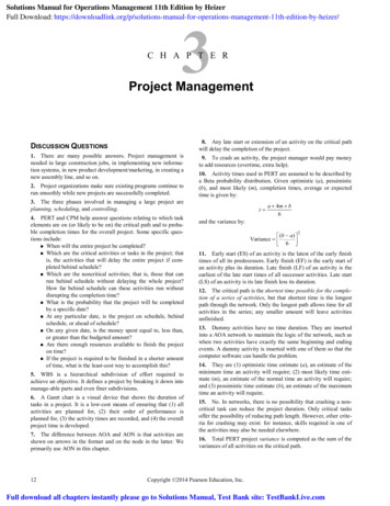
OverviewThe IOP ConceptA typical EZLogic -equipped conveyor may have several locations where controlinputs and/or outputs are needed. Figure 1 shows an example of a typicalconveyor and the required control wiring.Infeed conveyor “shutdown”output to PLC“Lane full” output to PLCZone stop input fromPLC, “product present”output to PLCConveyorFLOWDC “health” output toPLCPLC control panelControl wires routed toeach I/O pointFigure 1—Typical Conveyor Control Wiring Without IOPIn this example, there are four outputs from the conveyor being sent to the PLC,along with one input from the PLC to the conveyor: A zone stop input signal to control the accumulation and release ofcartons in the discharge zone. A “product present” output to inform the PLC of a carton present in thedischarge zone. A “lane full” output to inform the PLC that cartons have accumulated onthe conveyor almost back to the infeed end. An “infeed conveyor shutdown” output to inform the PLC that the conveyorcannot accept any more cartons from the upstream conveyor. An output from the “DC health” terminals in the power supply to monitorthe status of DC power on the conveyor.Page 5
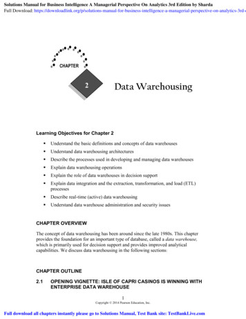
OverviewIn a traditional system each of these I/O points must be wired “locally.” That is,control wiring must be installed from the PLC control panel to each input oroutput at the point on the conveyor where the I/O is used, as illustrated in Figure1. In many installations this control wiring is run in conduit, adding material andlabor costs.In Figure 2, the same conveyor is illustrated using the IOP system for the controlwiring.Infeed conveyor “shutdown”output to PLC“Lane full” output to PLCConveyorZone stop input fromPLC, “product present”output to PLCFLOWDC “health” output toPLCControl signals passed throughnormal zone-to-zone wiringPLC control panelControl wires routed toone central locationFigure 2—Conveyor Control Wiring Using the IOP SystemThis example uses the same input and outputs as the previous example. Insteadof wiring the I/O points locally, all of the control wiring is routed to one centrallocation, the IOP unit. From there the signals are passed to and from each I/Opoint using the normal EZLogic zone-to-zone wiring. The EZLogic zonecontrollers in the I/O locations are configured to send and receive the propersignals to/from the IOP unit and on to the PLC.Page 6
OverviewIOP AdvantagesThe IOP system offers several advantages to the integrator, installer, and enduser. Some of these advantages are listed below: Reduced installation costs—The number of conduit runs and junctionboxes required, as well as the labor required to install them, is greatlyreduced. This eliminates the cost of these items from the installationequation. Easy to reconfigure—Inputs and outputs can be moved to other zoneson the conveyor without having to run new conduit and wiring. I/O can bereconfigured by physically moving zone controllers or by changing themthrough software. Central location for installation, I/O checking, andtroubleshooting—Since all control wiring goes to one location, installing,debugging, and troubleshooting inputs and outputs is simplified. Can be used for “peer-to-peer” communication betweencontrollers—A signal from one zone controller may be used as an inputto another zone controller several zones away, using the IOP system,without running any wires.Page 7
ComponentsComponentsThere are four key components of the EZLogic accumulation system that arerequired to use IOP control functionality. These work with the other componentsof the system to provide a feature-rich zero-pressure conveyor control package.The four key IOP components are: IOP unit IOP I/O board(s) installed in the IOP unit Enhanced EZLogic zone controllers in locations where I/O operationsare required Genesis configuration software and PC adapterIOP UnitThe IOP (Input/Output/Power) unit is a key component of the EZLogic system.The IOP unit performs two tasks:The unit provides power to the other EZLogic components. It converts 100130 VAC 1ph, or 210-250 VAC 1ph input power into the 27 VDC power requiredby EZLogic .The unit is the “hub” and controller for the IOP control wiring system. All IOPsignals are passed through the IOP unit, and all control wiring is connected here.Page 8
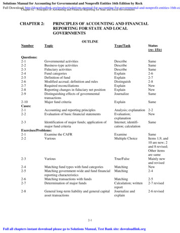
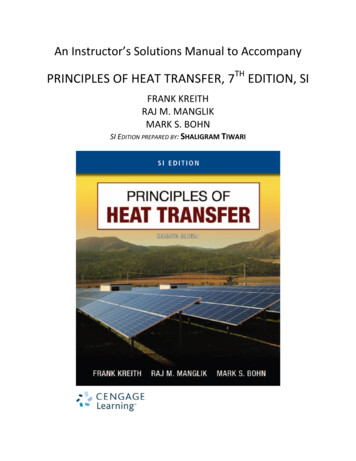
ComponentsFigure 3—IOP UnitIOP I/O BoardsThe I/O boards are the wiring point for control signals and install in the IOP unit(Figure 4). Each I/O board supports up to two I/O points, or channels. Thesemay be configured as inputs or outputs as required.Up to four I/O boards may installed in one IOP unit (Figure 5). This provides atotal of eight inputs and/or outputs that may be wired through a single IOP unit.A channel configured as an input accepts 24 VDC or 115 VAC control signals.The channel is considered “active” when a voltage is applied to the input.A channel configured as an output provides a solid-state relay, or “contactclosure” style output. This output may be used to switch a signal of 80mA @ 24VDC, or 80mA @ 115 VAC.Page 9
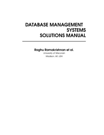
ComponentsFigure 4—IOP I/O BoardFigure 5—I/O boards installed in IOP UnitEnhanced EZLogic Zone ControllersThe EZLogic zone controller is the main element of the EZLogic accumulationsystem. There is one zone controller in every accumulation zone of the conveyor.There are two functional variations of the zone controller. Standard zonecontrollers provide the functionality needed in most zones of the conveyor. Theyare identified by the EZLogic logo with a yellow background. Enhanced zonecontrollers incorporate an expanded function set, including the ability to work withthe IOP system. They are identified by the EZLogic logo with a whitebackground.Page 10
ComponentsFigure 6—Enhanced Zone ControllerEnhanced zone controllers must be installed at the locations where control inputand/or output is required. Each enhanced controller may be configured to use avariety of input and output functions. The functions are each assigned to achannel, one function per channel. A single enhanced controller can beconfigured to use as many channels as required, up to the eight available fromthe IOP unit.Genesis Configuration Software and CableThe PC adapter cable with Hytrol’s Genesis configuration software providesaccess to the full feature set of the EZLogic zone controller. The cable plugs tothe auxiliary port of a zone controller and provides a 9-pin RS232 serial interfaceto a Windows PC through a built-in serial port or, by the use of a third-partyadapter, through an available USB port.Figure 7—PC Adapter and Genesis SoftwarePage 11
Installation & SetupInstallation and SetupHytrol zero-pressure accumulation conveyors equipped with the EZLogic system are pre-assembled at the factory. The proper setup procedure variesfrom conveyor model to conveyor model. The information in this manual refers totypical installations and, while accurate, may not be complete. Please refer to theinstallation and maintenance manual for your specific conveyor model forinformation about the physical setup of your conveyor.This section describes the basic installation and setup of the componentsrequired for IOP control communications. For specific information about zonecontroller removal and installation, IOP unit installation, etc, please refer to the“EZLogic Gen3 Component Manual.”The following steps are used to set up the IOP system:1. . .System layout/component selection2. . .I/O board setup and installation3. . .IOP unit setup and installation4. . .Enhanced zone controller setup and installation.System Layout/Component SelectionThe conveyor layout should be considered when selecting the requiredcomponents for IOP communications. There are three basic layouts that may beused when setting up IOP control wiring. They are: Single IOP unit Multiple IOP units, one IOP unit used as a wiring hub Multiple IOP units used as wiring hubsPage 12
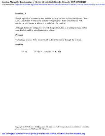
Installation & SetupSingle IOP UnitA conveyor using a single IOP unit is illustrated in the following figure:Input/Output locations on the conveyor—oneenhanced zone controller in each locationConveyorFLOWSingle IOP unit withIOP Enabled (hub)Control signals passed throughnormal zone-to-zone wiringI/O boards installed inIOP unit (up to 4boards for 8 channels)PLC control panelControl wires to/from PLCFigure 8—Single IOP UnitThis layout may be used when the system meets all of the following criteria: There are 50 zone controllers or less in the conveyor The conveyor line is 300 feet or less in length There are 8 inputs and/or outputs, or less, required on the conveyorThe single IOP unit layout is the simplest and most cost-effective way to takeadvantage of IOP control wiring technology. All control wiring is routed from thePLC control panel to the IOP unit.Page 13
Installation & SetupMultiple IOP Units, One IOP Unit Used as a Wiring HubThere are times when there is a conveyor line has more than fifty zones in azone controller chain. It is possible to do this by using multiple IOP units toprovide power to the zone controllers. The following illustration shows anexample of a conveyor line with multiple IOP units.Input/Output locations on the conveyor—oneenhanced zone controller in each locationConveyorPower IsolationCable (032.562)IOP unit with IOPEnabled (hub)IOP unit with IOPDisabled (default)Control signals routed tothe enabled IOP unit (“hub”)PLC control panelI/O boards installed inIOP unit (up to 4boards for 8 channels)Control wires to/from PLCFigure 9—Multiple IOP Units, One IOP Unit Used as a Wiring HubIn this layout, two IOP units are used to provide power to the zone controllers onthe conveyor line. One of the IOP units is configured to serve as the IOP hub forcontrol wiring, while the other is set to have IOP communications disabled. (Thisis the default factory setting for the IOP unit. See page 21 for more information.)All control wiring is routed from the PLC control panel to the IOP hub.A power isolation cable (032.562) must be installed between the regions of thezone controller chain powered by separate IOP units. The power isolation cableprevents power from “passing through” from one powered region to another,while allowing normal zone communication and IOP control signals to pass. ThisPage 14
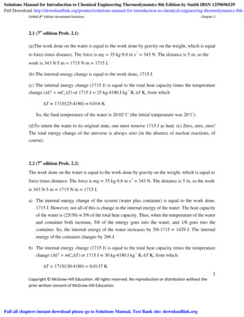
Installation & Setupcable prevents electrical interference between multiple power sources in thesame zone controller chain.This layout may be used when the system meets all the following criteria: The conveyor line is 300 feet or less in length There are 8 inputs and/or outputs, or less, required on the conveyor line No more than 50 enhanced zone controllers have I/O assigned to IOPchannelsThis layout offers the advantage that all inputs/outputs for the entire conveyorline are conveniently routed through one IOP hub.Multiple IOP Units Used as Wiring HubsIn applications where more than eight inputs/outputs are required on oneconveyor line, or where the conveyor line is longer than 300 feet, multiple IOPhubs may be used. This is illustrated in the following diagram.Enhanced zone controllers inthis area use IOP hub “A”Enhanced zone controllers inthis area use IOP hub “B”AIOP unit with IOPEnabled (hub)I/O boards installed inIOP unit (up to 4boards for 8 channels)BIOP IsolationCable (032.570)Control signalsrouted to theenabled IOPunits (hubs)PLC control panelIOP unit with IOPEnabled (hub)I/O boards installed inIOP unit (up to 4boards for 8 channels)Control wires to/from PLCFigure 10—Multiple IOP Units Used as Wiring HubsPage 15
Installation & SetupIn this layout, two IOP units are used to provide power to the zone controllers onthe conveyor line. Both units are also configured to serve as IOP hubs for controlwiring.The conveyor is divided into two IOP regions by an IOP isolation cable(032.570). This cable is similar to the power isolation cable in that it preventspower from “passing through” from one region to another, and allows normalzone communication to pass. However, the IOP isolation cable also prevents IOPcontrol signals from passing between regions. This allows each IOP hub tocontrol its associated region independently of the other.This layout may be used when the system meets all the following criteria: Each conveyor region is 300 feet or less in length There are 8 inputs and/or outputs, or less, required in each conveyorregion No more than 50 enhanced zone controllers in each region have I/Oassigned to IOP channelsThis layout allows the use of more than eight inputs/outputs on the sameconveyor line. It also allows the use of IOP control wiring on units longer than300 feet.I/O Board Setup and InstallationThe IOP I/O boards are the connection point for control wiring from the PLCcontrol panel. Each I/O board supports two IOP communications channels.These channels may be configured for use as inputs, outputs, or one of each.What are IOP Channels?The term “IOP channels” refers to the eight communications signals that areavailable through a single IOP unit. These channels are identified as “IOPchannel 1” through “IOP channel 8”. They provide connection between thecontrol signals connected to the I/O boards and the enhanced zone controllers inthe system.A channel becomes “active”, or on, when either: There is an active input signal from the PLC to the appropriate I/O board,or An enhanced zone controller has an output assigned to that channel thatis active.An “active” channel has the following effect on IOP components: If the I/O board I/O point for that channel is set to “output” then that outputto the PLC becomes active (“contact” is closed) If an enhanced zone controller has an input assigned to that channel, theinput becomes active in the zone controller.Page 16
Installation & SetupI/O Board SetupThe following illustration shows the key parts of an I/O board.BackplaneconnectorA1 A2 B2 B1SW1SW2InputOutput“Odd” channelscrew terminals“Even” channelI/O selectorswitch“Odd” channelI/O selectorswitch“Even” channelscrew terminalsGreen LED, onwhen switch is setto “input” modeRed LED, on whenswi
Genesis configuration software and PC adapter IOP Unit The IOP (Input/Output/Power) unit is a key component of the EZLogic system. The IOP unit performs two tasks: The unit provides power to the other EZLogic components. It converts 100-130 VAC 1ph, or 210-250 VAC 1p