Transcription
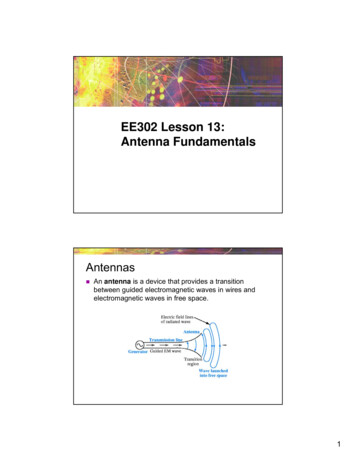
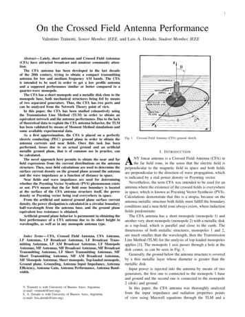
1On the Crossed Field Antenna PerformanceValentino Trainotti, Senior Member, IEEE, and Luis A. Dorado, Student Member, IEEEAbstract— Lately, short antennas and Crossed Field Antennas(CFA) have attracted broadcast and amateur community attention.The CFA antenna has been developed in the last decadeof the 20th century, trying to obtain a compact transmittingantenna for low and medium frequency AM bands. The CFAis intended to be used in order to get a low profile antennaand a supposed performance similar or better compared to aquarter-wave monopole.The CFA has a short monopole and a metallic disk close to themonopole base, both mechanical structures being fed by meansof two separated generators. Thus, the CFA has two ports andcan be analyzed from the Network Theory point of view.In this paper, the CFA has been studied exhaustively usingthe Transmission Line Method (TLM) in order to obtain anequivalent network and the antenna performance. Due to the lackof theoretical data to explain the CFA antenna behavior, the TLMhas been validated by means of Moment Method simulations andsome available experimental data.As a first approximation, the CFA is placed on a perfectlyelectric conducting (PEC) ground plane in order to obtain theantenna currents and near fields. Once this task has beenperformed, losses due to an actual ground and an artificialmetallic ground plane, that is of common use in practice, canbe calculated.The novel approach here permits to obtain the near and farfield expressions from the current distributions on the antennastructure. Then, near field calculations are used to determine thesurface current density on the ground plane around the antennaand the wave impedance as a function of distance in space.Near fields and wave impedance are used for determiningwhether the Poynting Vector Synthesis (PVS) phenomenon existsor not. PVS means that the far field zone boundary is locatedat the surface of the CFA antenna structure itself, the powerdensity or Poynting vector being real everywhere in space.From the artificial and natural ground plane surface currentdensity, the power dissipation is calculated in a circular boundaryhalf-wavelength from the antenna base, and the ground planeequivalent loss resistance is obtained.Artificial ground plane behavior is paramount in obtaining thebest performance of a CFA antenna due to its short height inwavelengths, as well as in any monopole antenna type.Index Terms— CFA, Crossed Field Antenna, CFA Antenna,LF Antennas, LF Broadcast Antennas, LF Broadcast Transmitting Antennas, LF AM Broadcast Antennas, LF MonopoleAntennas, MF Antennas, MF Broadcast Antennas, MF BroadcastTransmitting Antennas, LF Short Transmitting Antennas, MFShort Transmitting Antennas, MF AM Broadcast Antennas,MF Monopole Antennas, Short monopole, Top-loaded monopole,Ground plane, Grounding, Antenna Input Impedance, AntennaEfficiency, Antenna Gain, Antenna Performance, Antenna Bandwidth.V. Trainotti is with University of Buenos Aires, Argentina(e-mail: vtrainotti@ieee.org).L. A. Dorado is with University of Buenos Aires, Argentina(e-mail: luis dorado@ieee.org).Fig. 1.Crossed Field Antenna (CFA) general sketch.I. I NTRODUCTIONNY linear antenna is a Crossed Field Antenna (CFA) inthe far field zone, in the sense that the electric field isperpendicular to the magnetic field in space and both fieldsare perpendicular to the direction of wave propagation, whichis indicated by a real power density or Poynting vector.Nevertheless, the term CFA was intended to be used for anantenna where the existence of the crossed fields is everywherein space, which is known as Poynting Vector Synthesis (PVS).Calculations demonstrate that this is a utopia, because on theantenna metallic structure both fields must fulfill the boundaryconditions and a near field zone always exists, where inductionfields predominate.The CFA antenna has a short monopole (monopole 1) andanother very short monopole (monopole 2) with a metallic diskas a top-load, which is parallel and close to the earth. Thedimensions of both metallic structures, monopoles 1 and 2,are much smaller than the wavelength, then the TransmissionLine Method (TLM) for the analysis of top-loaded monopolesapplies [1]. The monopole 1 axis passes through a hole at thedisk center, as can be seen in Fig. 1.Generally, the ground below the antenna structure is coveredby a thin metallic layer whose diameter is greater than themetallic disk.Input power is injected into the antenna by means of twogenerators, the first one is connected to the monopole 1 baseand ground and the second one is connected to the monopole2 (disk) and ground.In this paper, the CFA antenna was thoroughly analyzedfrom the input impedance and radiation properties pointsof view using Maxwell equations through the TLM and aA
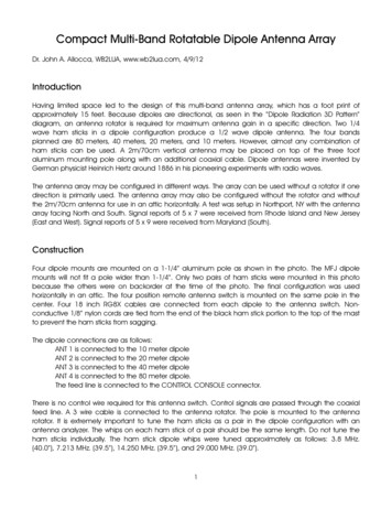
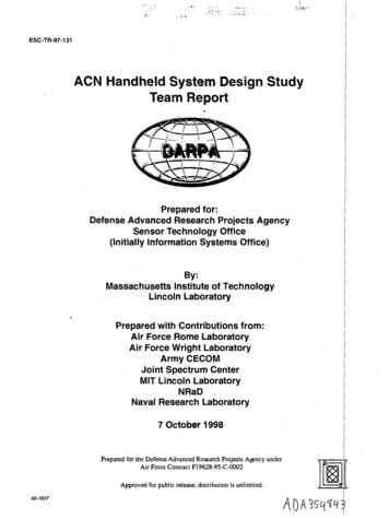
2Fig. 2.Crossed Field Antenna (CFA) feeding system.Moment Method approach. No serious theoretical analysis ofthis antenna has been found in the technical literature and onlypartial analysis made up by software simulations [2]–[5] orsome experiment with actual and reduced scale models [6]–[10]. Both intents do not explain clearly the actual antennaperformance, inventors explanations are too vague and theydo not support their invention by means of a clear theory inorder to assure its working performance [11]–[16].II. E QUIVALENT N ETWORKThe CFA antenna can be analyzed from a network point ofview, taking into account the two ports in the antenna structure.Monopole 1 base and ground are the port 1 terminals, whilemetallic disk (monopole 2) and ground are the port 2 terminals.A sketch of this antenna can be seen in Fig. 2.Generators are connected to both monopoles, 1 and 2 (disk),with short leads as it is usual in high and very high frequencytechniques. Pictures of some published CFA antennas havetheir feeding connections with long wires placed in the spaceoccupied by the near fields. It seems that this technique is thesame as used by electrical 50 or 60 Hz installations and itshould be avoided in RF frequency systems.The antenna equivalent network can be characterized by itsimpedance parameters, the monopole 1 self-impedance, Z 11 ,the monopole 2 self-impedance (disk), Z 22 , and the mutualimpedances, Z 12 and Z21 , between them.Fig. 3 shows the antenna equivalent network, where agenerator is connected to each port. Generator 1, connected toport 1, has a voltage V 1 , while generator 2, connected to port2, has a voltage V 2 . As soon as both generators are connectedto the antenna ports, currents I 1 and I2 will flow into theantenna structure.By using impedance parameters, the standard network equations can be written in matrix form as follows [17]–[19]: Z11 Z12I1V1 ·(1)V2Z21 Z22I2From the Reciprocity Theorem, it follows that Z 12 Z21 .Fig. 3.Crossed Field Antenna (CFA) equivalent network.Admittance parameters will also be required and are obtained by inverting the impedance matrix, that isY11 G11 j B11 Z22Z11 Z22 Z212Y12 Y21 G12 j B12 Y22 G22 j B22 Z12Z11 Z22 Z212Z11Z11 Z22 Z212(2)(3)(4)The impedance and admittance matrices are functions offrequency and the physical dimensions of the antenna system.A. Network ParametersThe CFA antenna can be considered as an array of twotightly coupled short monopoles. The first one is a monopoleof height H1 , which could have or not a top-load, while thesecond one is a monopole of height H 2 with the disk as itstop-load. These monopoles are shown in Figs. 4 and 5.Thus, the present theory is based on the Transmission LineMethod (TLM) outlined in [1] for the analysis of a top-loadedmonopole [20].When port 2 is an open circuit, the monopole 1 inputimpedance, Z 11 R11 j X11 , is the impedance of a shortmonopole with a given degree of top-loading.When port 1 is an open circuit, the monopole 2 inputimpedance, Z 22 R22 j X22 , is the impedance of anothervery short monopole with the disk as its top-load (practicallya Hertz monopole).Self-resistance and reactance of each monopole are givenby [1]Rii Rradi Rci RgpiXii Z0miZ0mi tan βHi XtiZ0mi Xti tan βHii 1, 2i 1, 2(5)(6)
3Due to a very small disk height, H 2 , over the ground planeand a disk radius, L 2 , greater than this height, the currentdistribution on monopole 2 is practically constant, thereforeHe2 H2(9)The top-reactance of monopole 1, X t1 , is [1]Xt1 Fig. 4.Z0t1n tan βL1(10)WhereZ0t1 is the monopole 1 top-load characteristic impedance[1] [Ω].L1 is the monopole 1 top-load length [m].n is the number of top-load branches of monopole 1.CFA monopole 1 current distribution.The top-reactance of monopole 2, X t2 , isXt2 12 π f C2(11)Where the disk capacitance, C 2 , can practically be calculated as a simple capacitor with a circular plate of radius L 2and a separation from the ground plane equal to the monopole2 height, H2 , thenC2 0π L22H2(12)When port 2 is an open circuit, the mutual impedance Z 21is the ratio between the open circuit voltage in port 2 and thecurrent flowing in port 1, that isFig. 5.CFA monopole 2 and top-loading disk current distributions.Z21 WhereRradi is the i-th monopole radiation resistance [Ω].Rci is the i-th monopole conductor resistance [Ω].Rgpi is the i-th monopole ground plane loss resistance [Ω].Z0mi is the average characteristic impedance of the ithmonopole equivalent transmission line [1] [Ω].Xti is the ith-monopole top-reactance [Ω].Hi is the ith-monopole height [m].The i-th monopole radiation resistance is [21]–[23]Rradi 40 (βHei )2i 1, 2(7)Where Hei is the i-th monopole effective height, whichdepends on the vertical wire current distribution, and it is givenbyβHei sin βHi Xii(1 cos βHi )Z0mii 1, 2(8)V2 I1 I2 0(13)Also, the open circuit voltage V 2 is due to the electric fieldEz1 between the capacitor plate and ground [24], according tothe current I1 in port 1, thenZ21 Ez1 H2 I1I2 0(14)The electric field Ez1 is the near field produced by monopole1 in the space surrounding the antenna and can be calculatedby means of (22).Another possibility to calculate the impedance and admittance parameters is using the Method of Moments (MoM),which has been used extensively by means of our own software[25], but similar results could be obtained by means of otherstandard softwares. These parameters are practically the samefor both techniques, Transmission Line Method (TLM) andMoM, as practical examples indicate.Nevertheless, it is important to have at hands the electromagnetic equations in order to solve the problem and have aclear view of the antenna behavior.
4B. Input ImpedancesThe antenna is excited by means of two generators, for thisreason, monopole 1 input voltage V 1 will be taken as the phasereference and monopole 2 input voltage V 2 will be given byV2 K V1 ej φ2(15)Thus, the parameter K is the amplitude ratio between V 1 andV2 , while φ2 is the phase difference between them. Voltagesand currents are taken as effective values.The port 1 input impedance isV11 I1Y11 Y12 K ej φ2The port 2 input impedance isZ1 R1 j X1 (16)V2K (17) jφI2Y12 e 2 K Y22It can be seen that the input impedances depend on a stronginteraction between both generators.Z2 R2 j X2 Fig. 6. a) CFA operating in the first regime (I) G12 0. b) CFA equivalentcircuit.C. Input PowerThe active or real power W 1 I1 2 R1 , produced bygenerator 1, is given byW1 V1 2 (G11 K G12 cos φ2 K B12 sin φ2 ) (18)The active or real power W 2 I2 2 R2 , produced bygenerator 2, is given byW2 V1 2 (K2 G22 K G12 cos φ2 K B12 sin φ2 ) (19)Then, the total input power will be the sum of the inputpowers of both generators, W in W1 W2 , that isWin V1 2 (G11 2 K G12 cos φ2 K2 G22 )(20)Equation (20) shows that the input power depends on thecosine of the voltage phase difference φ 2 . For this reason,there are three cases:Fig. 7. a) CFA operating in the second regime (II) G12 0. b) CFAequivalent circuit.(I) When G12 0, the input power is maximum forφ2 0 (360 ) and minimum for φ 2 180 .(II) When G12 0, the input power is maximum forφ2 180 and minimum for φ 2 0 (360 ).(III) When G12 0, the input power is constant for anyvalue of φ2 .III. E LECTROMAGNETIC F IELDThese three cases or regimes depend on the antenna physicaldimensions and frequency, and once these are given, theantenna will operate in only one of those regimes.In Fig. 6, a CFA operating in the first regime is shown(G12 0, φ2 0) as well as the antenna equivalent circuit,where the currents of both generators are in phase. In Fig. 7a CFA operating in the second regime is shown (G 12 0,φ2 180 ), where the generator currents are out of phase.When G12 0, the CFA will operate either as in Figs. 6 or 7according to the highest voltage generator, however, the totalinput power will be independent of φ 2 .The electromagnetic field radiated from the antenna is thesum of the radiation produced by the array of the two CFAmonopoles. Monopole 1 is a top-loaded short vertical antennaand monopole 2 is practically a Hertz monopole makes up bythe disk and its feeding vertical lead.Because of the very short distance between both radiators,the radiation center is located on the CFA vertical geometricaxis at a zero height. The feeding currents of each radiatingsource have different amplitudes and phases depending on thevoltages of both generators.A. Near FieldThe near field of a top-loaded monopole has been determined in [1] using Image Theory, according to Fig. 8geometry.Then, the magnetic and electric near fields of bothmonopoles on the ground plane, at z 0, are given by [1]
5Hφ Hφ1 Hφ2(23)Ez Ez1 Ez2(24)On the surface of the earth, a thin metallic layer of radius R 0is laid down, which is called the artificial ground plane. Fromthis metallic layer radius R 0 , the bare soil is considered up toa distance of half-wavelength. This is the surface of the earthto be taken into account in the soil power loss calculations.Over the metallic layer or artificial ground plane the electric field is practically perpendicular, having only the E zcomponent, due to the boundary conditions of a very highconductivity medium, where the surface impedance Z g is givenby [26], [27]Fig. 8. Monopole geometry used to calculate the near field in cylindricalcoordinates.Hφi ImiHijψi jβ(ri Hi ) jβρe e1 e(21)4πρri Hi e jψi 1 e jβ(ri Hi ) e jβρriEzi j Imi4 π 0 ω ρ ejψi(22)ρ e jβ(ri Hi )ri HiHi jβ 1 r2iri e jψiρ e jβ(ri Hi )ri HiHi jβ 1 r2iri jβ e jβρri ρ2 H2i 2XiiImi Ii 1 Z0mi Xiiψi arctanZ0miIt is assumed, as in [1], that only the vertical part of a toploaded monopole produces a net electromagnetic field. Thedistance ρ along the surface of the earth is measured from thecenter of the cylindrical coordinates or antenna vertical axis.The CFA total near electromagnetic fields on the groundplane (z 0) will beρ R0(25)(26)Where Zs is the bare soil impedance, which can be calculated from the soil conductivity, σ, and permittivity, , asfollows [26], [27]j ω µ0σ jω forρ R0(27)B. Wave ImpedanceThe wave impedance in space, just above the earth surfacein the air, is the ratio between the near electric and magneticfields Ez and Hφ on the ground plane, and is a function ofdistance ρ/λ, thereforeZ0 Where i 1, 2 andforEρ Zs HφZs Rs j Xs ω µ0(1 j)2 σmWhere σm is the metallic layer conductivity.On the bare soil, the electric field develops a radial component Eρ due to the low conductivity compared to that of themetallic layer, and is given by j β e jβρ Zg Rg j Xg EzHφ(28)In the far field zone, ρ λ, the wave impedance ispractically equal to the free space intrinsic impedanceZ00 120π Ω. The wave impedance Z 0 is almost pureimaginary or reactive very close to the antenna and almost purereal or resistive at a distance greater than half-wavelength.C. Far FieldIn the far field zone, when spherical coordinates are used,the CFA total far electric field E θ will be the sum of themonopoles 1 and 2 far electric fields, E θ1 and Eθ2 , which aregiven by [22], [23]Eθi j 60 Ii βHeiWheree j β rsin θri 1, 2(29)
6r is the distance from the antenna to any point in space [m].θ is the zenith angle.The total far electric field, E θ Eθ1 Eθ2 , will beEθ j 60 ( I1 βHe1 I2 βHe2 )e j β rsin θr(30)This equation is exactly the same as for any standard shortmonopole. This field is the non attenuated radiated electricfield, because it depends only on the inverse distance law.The actual field intensity along the earth is affected by thesoil physical constants and the diffraction due to the sphericalearth [28], [29].Thensin θrWhere the CFA effective height H e is defined as I2 He2 He He1 1 I1 He1 Eθ 60 I1 βHeIV. A NTENNA T UNING AND L OSSES(31)(32)Therefore, the CFA radiation resistance referred to monopole 1 can be defined as2Rrad 40 (βHe )(33)orRrad 2 I2 He2 40 (βHe1 ) 1 I1 He1 2(34)It is very important to understand that this radiation resistance is not the input resistance in any of the antenna portsand it depends on the current and effective height relationshipsof both monopoles.The antenna radiated power can be calculated asWrad I1 2 RradQLi XLiRLii 1, 2(41)Where RLi and XLi are the i-th monopole tuning coilresistance and reactance, respectively.Network parameters can be written in the following waywhen losses and tuning coils are present:Zii Z ii Rci Rgpi RLi j XLii 1, 2(42)(35)Then, monopole 1 effective input current I 1 , for a givenradiated power W rad , becomes Wrad I1 (36)RradEquations (31), (33) and (36) give the following far effectiveelectric field: 30 Wrad D Eθ sin θ(37)rThus, the CFA antenna directivity is D 3 due to the sin θfar field radiation pattern, as given by any short monopole ofheight less than 0.1λ, as was confirmed by antenna patternmeasurements using a model [6].Taking into account the antenna efficiency η, the radiatedpower Wrad and gain G are given by [26]Wrad η Win(38)G ηD(39)Then, the CFA far effective electric field becomes 30 Win G Eθ sin θrIn the antenna circuit there are losses in conductors, insulators, tuning system and in the earth surface within a circlehalf-wavelength in radius. In general, insulator losses are verylow compared to the other and can be neglected.In order to tune the antenna, a coil is connected in series toeach port, obtaining real input impedances. These coils havemerit factors given by(40)Z12 Z21 R12 j X12(43)WhereZ ii Rradi j Xii is the i-th monopole self-impedancewith no losses and no tuning coils [Ω].Rradi is the i-th monopole radiation resistance [Ω].Rci is the i-th monopole conductor resistance [Ω].Rgpi is the ground plane loss resistance due to the i-thmonopole current distribution and soil conditions [Ω].The mutual resistance R 12 and all the reactances are practically not affected by the antenna losses, because they dependon the very near field distribution, which is not appreciablyaffected by the finite soil conductivity [30], [31].The CFA equivalent network with losses and tuning coilscan be seen in Fig. 9.A. Conductor Loss ResistanceConductor loss resistance R c1 , due to monopole 1 conductors, can be calculated using the following expression,determined from the current distribution on the monopolestructure and its top-load [1]:
7X11 is the monopole 1 self-reactance [Ω].Z0m1 is the monopole 1 average characteristic impedance[Ω].H1 is the monopole 1 height [m].L1 is the monopole 1 top-load length [m].n is the number of the monopole 1 top-load branches.Fig. 9.The current distribution of the top-loaded monopole hasbeen determined in [1] and can be seen in Fig. 4.Conductor resistance per unit length, taking into account theskin effect, is given by [26] f µ01RcL1 (45)a1 4 π σcCFA equivalent network with losses and tuning coils.Whereσc is the conductor conductivity [S/m].a1 is the wire radius [m].f is the operation frequency [Hz].If the disk radius L 2 is sufficiently smaller than the wavelength, a linear current distribution over the disk can beassumed, as shown in Fig. 5, thereforeI(ρ) I2L2 ρL2 r hr h ρ L2(46)WhereI(ρ) is the current distribution over the disk [A].I2 is the effective current at the disk center [A].L2 is the disk radius [m].rh is the disk hole radius [m].The disk feeding lead has a constant current distribution likea Hertz monopole (I(z) I 2 in Fig. 5). From the disk andfeeding lead current distributions, the monopole 2 conductorresistance, Rc2 , can be calculated (see Appendix A), thereforeFig. 10. CFA near electric field lines (displacement current) and groundplane surface conductive currents.Rc1 RcL12 1 X211Z20m1 (47)The feeding lead conductor resistance per unit length, R cL2 ,is given by (45) with subscript 2 instead of 1.H1 X11 1 cos 2βH1X211 sin 2βH1 1 2Z0m12βZ0m1β 2 1X11sin βH1cos βH1 nZ 0m1 1 L1 1 tan2 βL1 cos 2βL1 11sin 2βL1 1 2ββ tan βL1tan2 βL1 ω µ01Rc2 RcL2 H2 24π (L2 rh )2 σc 2LL r2h222L2 ln 2 L2 (L2 rh ) rh2B. Ground Plane Loss ResistanceThe artificial ground plane [32] is made up by means of acircular metallic layer R 0 in radius with a small surface resistance Rg . Then, the ground plane equivalent loss resistancefor each monopole is given by [1](44)WhereRcL1 is the monopole 1 wire resistance per unit length[Ω/m].Rgpi2π Ii 2 R00 Hφi Rg ρ dρ 2λ/2 Hφi Rs ρ dρ2R0(48)Where i 1, 2 andRgpi is the i-th monopole ground plane loss resistance [Ω].
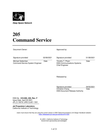
8Hφi is the i-th monopole near magnetic field on the groundsurface, given by (21) [A/m].Rg is the surface resistance of the artificial ground plane ormetallic layer, given by (25) [Ω].Rs is the surface resistance of the natural ground plane orsoil, given by (27) [Ω].Fig. 10 shows a sketch of the displacement currents and theconductive currents flowing on the ground plane at a specifictime.The ground plane is considered up to a distance ρ λ/2because this is the maximum distance covered by the groundsurface currents under the antenna, closing the antenna electriccircuit. Beyond this distance, the ground currents do not returnto the antenna generators and are taken into account in thesurface wave propagation calculations [1].V. E FFICIENCY AND G AINAntenna efficiency η is defined as the ratio between theradiated power W rad and the input power W in . The powerradiated by the CFA antenna is given by (35), while theantenna input power can be written asWin I1 2 R1 I2 2 R2(49)Where Ri is the i-th port input resistance, i 1, 2.Then, the CFA efficiency will beη RradR1 I2 /I1 2 R2(50)Where 2 2 I2 K 2 Z1 (51) I1 Z2 and the input impedances Z 1 and Z2 are given by (16) and(17), respectively.It can be seen that the CFA efficiency η depends on theantenna geometry, operation frequency, the voltage amplituderatio K and the phase difference φ 2 .Antenna gain, taking into account the directivity D 3, isG η D 3 η.VI. BANDWIDTHThe CFA antenna has two ports, for this reason, two bandwidths can be defined, according to the reflection coefficientsof both ports. In this case, taking into account that both inputpowers, W1 and W2 , must be positive, it is more convenientto define a CFA average reflection coefficient as a weightedgeometric mean of the reflection coefficients, Γ 1 and Γ2 , ofboth ports. Thus, the CFA average reflection coefficient isgiven by Γ W1 Γ1 2 W2 Γ2 2Win(52)Then, the CFA VSWR will beVSWR 1 Γ 1 Γ (53)TABLE ICFA DIMENSIONS IN METERS .Monopole 1 heightH110Barrel diameterD13.0Monopole 1 top-load lengthL10.0Barrel base heightδ11.5Monopole 1 wire radiusa16 · 10 31.0Monopole 2 (disk) heightH2Disk radius (monopole 2 top-load length)L22.5Disk hole radiusrh0.05Monopole 2 wire radiusa26 · 10 3Artificial ground plane radiusR05.0TABLE IICFA EQUIVALENT NETWORK MATRIX .METHODZ11Z12Z22TLM2.18 j 4100.11 j 1240.09 j 856MoM2.13 j 4300.20 j 1170.13 j 844VII. E XAMPLESHaving the available theory expressed previously, theCrossed Field Antenna analysis can be made by means ofnumerical examples.A. CFA Operating WindowsAs a first example, a CFA model is analyzed at the frequency of 1 MHz, with the antenna dimensions indicated inTable I and over average soil (σ 10 2 S/m, r 10).The CFA equivalent network impedance matrix can becalculated using the Transmission Line Method (TLM) andby means of the Method of Moments (MoM) [33] (wire gridmodel [25]). Both methods produce practically the same result,as can be seen in Table II for 1 MHz and average ground.In this example, monopole 1 is a barrel build up by twentyfour copper wires (σ c 5.8 · 107 S/m) of radius a 1 , as shownin Fig. 4. Barrel diameter, D 1 , wire radius, a 1 , and barrel baseheight, δ1 , are taken into account in the calculation of themonopole 1 equivalent transmission line average characteristicimpedance Z 0m1 [1].As a first analysis, input impedances of both antenna portsare calculated as functions of voltage phase difference φ 2 forK 1 and over average ground, and can be seen in Figs. 11and 12.In Fig. 11, negative input resistances R 1 and R2 can be seenfor some ranges of φ 2 , while in Fig. 12 the input reactances X 1and X2 are always negative. There exist two small windows,difficult to appreciate in Fig. 11, where both input resistancesare positive, permitting the antenna operation. One window islocated in the neighborhood of φ 2 180 and the other nearφ2 360 .Input impedances are shown in both windows in Tables IIIand IV. It is interesting to see that the input reactances arepractically constant in both windows, where the antenna canoperate.
9R1RR1R300R1R22[Ω] 20052[Ω]01000 5 100R1R2 200φ2 [ ] 30003060φ [ ]2 100306090 120 150 180 210 240 270 300 330 36090 120 150 180 210 240 270 300 330 360Fig. 11. CFA input resistances R1 and R2 as functions of φ2 for K 1and over average ground.Fig. 13. Tuned CFA input resistances R1 and R2 as functions of φ2 forK 1. The 180 -window can clearly be seen where R1 and R2 are positive.X1 300X2 400X1X2[Ω] 500[Ω]6X1X242 600 7000 800 2 900X1X 1000 1100 12000 4φ [ ]23060290 120 150 180 210 240 270 300 330 360Fig. 12. CFA input reactances X1 and X2 as functions of φ2 for K 1and over average ground.φ2 [ ] 60306090 120 150 180 210 240 270 300 330 360Fig. 14. Tuned CFA input reactances X1 and X2 as functions of φ2 forK 1 and in the 180 -window.TABLE IIICFA INPUT IMPEDANCES IN 180 - WINDOW.φ2R1X1R2degΩΩΩΩ179.42.30 343 0.71 629179.82.00 3430.31 629180.21.70 3431.32 629180.61.39 3432.34 629181.01.09 3433.36 629181.40.79 3434.37 629181.80.49 3435.39 629182.20.19 3436.41 629182.6 0.12 3437.42 629X2TABLE IVCFA INPUT IMPEDANCES IN 360 - WINDOW.φ2R1X1R2degΩΩΩΩ358.0 0.12 45915.7 1171358.20.15 45914.0 1171358.40.42 45912.2 1171358.60.69 45910.4 1172358.80.96 4598.67 1172359.01.23 4596.90 1172359.21.50 4595.14 1172359.41.77 4593.37 1172359.62.04 4591.61 1172359.82.31 459 0.16 1172X2In order to tune the antenna, opposite reactances are connected in series to both ports. If the 180 -window is chosen,the reactance to be connected in series with port 1 isXL1 343 Ω and with port 2 is X L2 629 Ω. Under thiscondition, the input resistances and reactances of both portsare shown in Figs. 13 and 14, where they have a very smallvariation as functions of φ 2 , also the input impedances ofboth ports are practically real close to φ 2 180 . In thisexample, only the antenna losses are taken into account andthe tuning coils are supposed to be of infinite merit factorQL QL1 QL2 , permitting to know the antenna operationwithout any other effect.In the 180 -window, when the generators have the samevoltage amplitude (K 1), the antenna is operational becausethe input powers on both ports are positive for φ 2 between 50 and 290 , where both input resistances are positive. In thiscase, the equivalent network mutual conductance is negative,G12 0.253 S, and the antenna operates as in Fig. 7.If the 360 -window is chosen, the reactance to be connectedin series with port 1 is XL1 459 Ω and with port 2 isXL2 1172 Ω. Under this condition, the input resistancesand reactances of both ports are shown in Figs. 15 and 16,where they also have a very small variation as functions ofφ2 . The input impedances of both ports are practically realfor φ2 between 0 and 100 and between 240 and 360 .In this case, the antenna is operational too, because the inputpowers in both ports are positive. Also, because the equivalentnetwork mutual conductance is positive, G 12 0.165 S, the
10R1RTABLE V5CFA PERFORMANCE IN 180 - WINDOW.2[Ω]Kφ2R1X1R2X2 degΩΩΩΩΩ1.6130.61.040.683.47 1.080.591.7155.31.040.423.50 073.540.950.602.0209.61.05 0.103.551.530.602.1230.31.05 0.323.582.280.60KV1 V2 I1 I2 GE VVAAdBimV/m1.627.343.621.912.0 0.691601.724.741.921.912.0 0.691601.823.442.221.911.9 0.691601.922.943.521.911.9 0.6816042.023.045.921.911.9 0.6816022.123.950.221.911.8 0.681600 5R1R2 1003060φ2 [ ]90 120 150 180 210 240 270 300 330 360Fig. 15. Tuned CFA input resistances R1 and R2 as functions of φ2 forK 1. The 360 -window can clearly be seen where R1 and R2 are positive.X1X2[Ω]8X1X26Rrad0TABLE VICFA PERFORMANCE IN 360 - WINDOW. 2 4 6 80φ2 [ ]306090 120 150 180 210 240 270 300 330 360Fig. 16. Tuned CFA input reactances X1 and X2 as functions of φ2 forK 1 and in the 360 -window.antenna operates as in Fig. 6.From this analysis, the range of the voltage phase differenceφ2 was obtained under antenna resonance condition, when theinput impedances of both ports are practically real or resistive.The φ2 value of interest in these ranges or windows is thatwhich permits to have the input powers, W 1 and W2 , undercontrol, with a given relationship K w W2 /W1 .In some cases, it is possible to find values of K, φ 2 and V1 ,which permit to get a given total input power,Win W1 W2 , and a given power ratio K w W2 /W1 ,under the conditions W 1 0 and W2 0. In other
3 Fig. 4. CFA monopole 1 current distribution. Fig. 5. CFA monopole 2 and top-loading disk current distributions. Where Rradi is the i-th monopole radiation resistance [Ω]. Rci is the i-th monopole conductor resistance [Ω]. Rgpi is the i-th monopole ground plane loss resistance [Ω]. Z0mi is the average characteristic impedance of the ith- monopole equivalent transmission line [1] [Ω].