Transcription
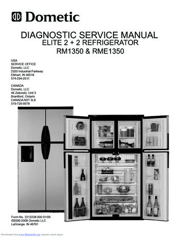
DIAGNOSTIC SERVICE MANUALELITE 2 2 REFRIGERATORRM1350 & RME1350USASERVICE OFFICEDometic, LLC2320 Industrial ParkwayElkhart, IN 46516574-294-2511CANADADometic, LLC46 Zatonski, Unit 3Brantford, OntarioCANADA N3T 5L8519-720-9578Form No. 3312238.000 01/09 2006-2008 Dometic LLCLaGrange, IN 46761Downloaded from www.Manualslib.com manuals search engine
Safety InstructionsForewordThis service manual is the result of the dedication of Dometic Corporation technical staff andits engineers in giving service people the necessary instruction for making accurate analysesof certain conditions. Provided is a diagnosticchart leading a qualified mechanic into the service manual pages to locate and solve symptoms which may occur. Dometic has continuedits commitment in providing service people withthis, the most up-to-date information about servicing Dometic RV accessories.This manual has safety information and instructions to help users eliminate or reduce the riskof accidents and injuries.Recognize Safety InformationThis is the safety-alert symbol. When you see thissymbol in this manual, be alert to the potentialfor personal injury.Follow recommended precautions and safe operating instructions.Understand Signal WordsA signal word, WARNING OR CAUTION is usedwith the safety-alert symbol. They give the levelof risk for potential injury.Indicates a potentially hazardous situation which, if not avoided, could resultin death or serious injury.Indicates a potentially hazardous situation which, if not avoided may result inminor or moderate injury.When used without the safetyalert symbol indicates, a potentially hazardoussituation which, if not avoided may result in property damage.Read and follow all safety information and instructions.1Downloaded from www.Manualslib.com manuals search engine
CONTENTSPAGE NO.DIAGNOSTIC FLOW CHART.4SECTION 1OPERATIONRefrigerator Overview & Operation .6SECTION 2AC VOLTAGEAC Voltage Requirements.16SECTION 3AC COMPONENTS3.1 Heating Element .163.2 AC Icemaker Water valve.163.2 Control Module Water Valve & Auger.173.4 Auger.17SECTION 4DC VOLTAGEDC Voltage Requirements .18SECTION 5DC .135.145.155.165.17Thermistor .19Solenoid Valve.19Igniter .19High Voltage Cable .20Electrode.20Climate Control Heater.20Thermofuse.20Door Switches .21Control Panel .21LED Display Panel .21Flap Heater Wire.21Lower Board .22Fuses .23DC Water Dispenser Valve.23Automatic Door Lock.24DC Relay.24Ventilator Fans.24SECTION 6Wiring6.16.2Internal Wiring .24External Wiring.302Downloaded from www.Manualslib.com manuals search engine
CONTENTSPAGE NO.SECTION 7LP GAS REQUIREMENTS.30SECTION 8GAS COMPONENTS8.18.28.38.48.58.6Manual Gas Shutoff Valve.30Orifice .31Thermocouple.31Burner . .32Flue Baffle.32Flue Tube.32SECTION 9COOLING ion.33Air Leaks.37Interior Liner Seal to Frame.37Door Position.38Ambient Temperature.38Cooling Unit.38Food Storage.38High Humidity.38SECTION 10ERROR CODES10.1 Codes .40SECTION 11DIAGNOSTIC MODE11.1Diagnostic Test .40SECTION 12ICE MAKER12.1 Operation.4112.2 Mold Heater.4112.3 Ice Ejector.4112.4 Mold Thermostat.4112.5 Shut Off Arm.4212.6 Mold Switches.4212.7 Timing Motor.4212.8 Water Valve.4212.9 Ice Maker Replacement.4312.10 Water Fill Adjustment.4312.11 Water Supply.4312.12 Wiring Schematics .433Downloaded from www.Manualslib.com manuals search engine
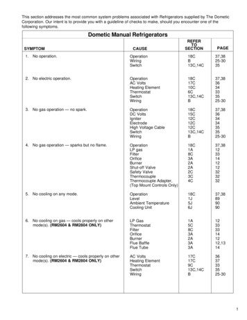
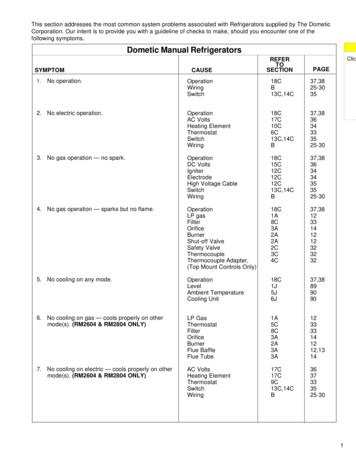
This program will address the most common system problems associated with the RM1350 refrigerator supplied by Dometic LLC. Our intent is to provide you with a guideline of checks to make, should you encounter one of the followingsymptoms.SymptomCauseSection & Page1. No operation - no panel lightsOperationDC VoltsFuseWiringControl PanelLED Display BoardLower Circuit Board1, Page 134, Page 185, Page 235, Page 21 & 6, page 305, Page 215, Page 215, Page 222. No operation - has panel lightsOperationDC VoltsThermistorWiringLower Circuit Board1, Page 134, Page 185, Page 195, Page 21 & 6, page 305, Page 223. No AC operation - operates on gas modeOperationAC VoltsFuseHeating ElementWiringLower Circuit Board1, Page 132, Page 165, Page 233, Page 165, Page 21 & 6, Page 305, Page 224. No Gas operation - operates on AC modeOperationLP GasManual Gas ValveIgniterHigh Voltage CableElectrodeSolenoidWiringLower Circuit Board1, Page 137, Page 308, Page 305, Page 205, Page 205, Page 205, Page 195, Page 21 & 6, Page 305, Page 135. Insufficient cooling on all modes.VentilationLevelingAmbient TemperatureAir LeaksThermistorCooling Unit9, page 339, page 339, page 389, page 375, page 199, page 386. Insufficient cooling on AC - cools properly on gas mode.AC VoltsHeating ElementLower Circuit Board2, page 163, page 165, page 227. Insufficient cooling on Gas - cools properly on AC mode.LP GasOrificeFlue BaffleFlue TubeBurnerLower Circuit Board7, page 308, page 318, page 328, page 328, page 325, page 224Downloaded from www.Manualslib.com manuals search engine
SymptomCauseSection & Page8. Freezes.ThermistorLower Circuit BoardDC Volts5, Page 195, Page 224, Page 189. Check LP flashingDC VoltsWiringLP GasManual Gas ValveSolenoidOrificeBurnerThermocoupleLower Circuit Board4, page 185, page 21 & 6, page 307, page 308, page 305. page 198. page 318. page 328. page 315. page 2210. Interior light on when door is closedWiringDoor SwitchDoor Position5. page 21 & 6, page 305. page 218. page 2111. Rapid formation of frostFood StorageInterior Liner to FrameHigh HumidityAir Leaks8. page 218. page 208. page 218. page 2012. Water on frameInterior Liner to FrameHigh HumidityAir LeaksClimate Control Heater8. page 208. page 218. page 205. page 2013. Intermittent warming up of fridgeAutomatic C/U cycling system1. page 125Downloaded from www.Manualslib.com manuals search engine
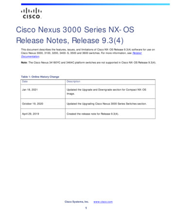
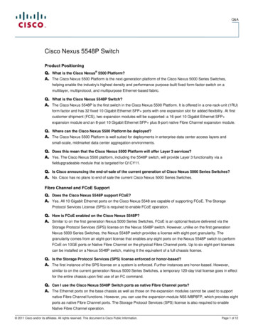
SECTION 11.1 Refrigerator OverviewMODELS WITH MANUAL DOOR LOCKING SYSTEMSControl PanelLED DisplayIce BucketManual Travel LatchDoor CompartmentFinned Cooling PlateShelfDrip ProtectionDraining PipeCrispersThis is a general view of the appliance. The Model shown is equipped with ice maker. Thenumber of shelves and door compartments mayvary according to the model.6Downloaded from www.Manualslib.com manuals search engine
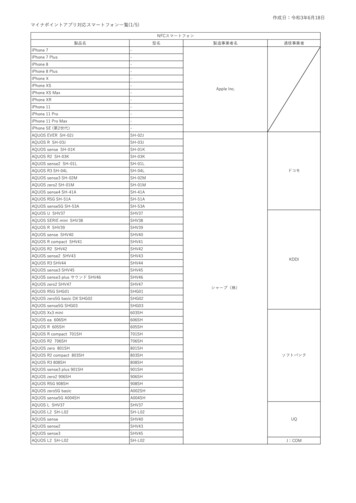
SECTION 1MODELS WITH THE AUTOMATIC DOOR LOCKING SYSTEMAND EQUIPPED WITH WATER DISPENSERControl PanelLED DisplayIce BucketAutomaticTravel LatchWater Dispensernot on all unitsDoor CompartmentFinned Cooling PlateShelfDrip ProtectionDraining PipeCrispersThis is a general view of the appliance. The Model shown is equipped with ice makerand water dispenser. The number of shelves and door compartments mayvary according to the model.7Downloaded from www.Manualslib.com manuals search engine
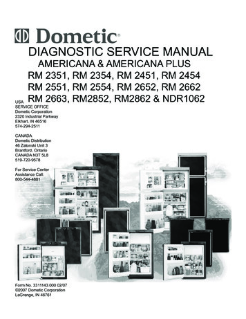
SECTION 1MODELS WITH THE AUTOMATIC DOOR LOCKING SYSTEM ANDEQUIPPED WITH ICE AND WATER DISPENCERControl PanelLED DisplayIce BoxAutomaticTravel LatchDrip Tray topof lower doorDoor CompartmentFinned Cooling PlateDrip ProtectionDraining PipeShelfCrispersThis is a general view of the appliance. The number of shelves and door compartments mayvary according to model.8Downloaded from www.Manualslib.com manuals search engine
DISPLAY PANEL RM1350 & RME1350Refrigerator Control PanelsRM1350 DisplayRME1350 Display1. Main Power Button ON/OFFPress the button to turn the refrigerator on or off.2. AUTO/GAS Mode Selector ButtonPress the button to turn the auto mode on or off.3. TEMP. SET ButtonThe thermostat has 5 settings where 1 indicates thewarmest and 5 the coldest temperature setting. Pressthe button repeatedly until the desired setting, e.g. 3,is shown in LED display. This value is shown for about5 seconds and then the temperature is displayedagain, e.g. 43.9Downloaded from www.Manualslib.com manuals search engine
LED Display PanelThe LED display panel provides a quick visual indicator of the temperature of the food in the fresh food cabinet, statusmessages, and alarm conditions. For RM1350XXX, the AUTO and LP mode indication lamps show the mode of operation.LED PANEL INDICATIONSRM1350M,RM1350IM& RM1350WIDSTATUS INFORMATIONRME1350WIMFresh food temperatureThermostat range setting indication (1-5). Temporary during setting. The thermostat settings are stored automatically after 5 sec.of inactivity60 is displayed. Indicates that the temperature is above measurement range----AUTO mode is lit. Indicates AUTO mode and AC operation----AUTO and LP mode lamps are lit. Indicates AUTO mode and GASoperation----LP mode lamp is lit. Indicates manual gas operation mode----LP is flashing (message alternates between LP and the temperature). Indicates gas operation lockout. Check gas----AUTO mode lamp is lit and LP mode lamp is flashing. Indicatestemporary gas operation lockout10Downloaded from www.Manualslib.com manuals search engine
Models WithSystemAutomaticDoorLockingThe refrigerator is equipped with a travel latch that automatically locks the refrigerators doors when the RVs engine is running. When the RV’s engine is off, the travellatch unlocks the doors.3. Verify that a small spacing has been created betweenthe cabinet and the doors and that the doors have notbeen closed completely. If so, unlock the latch and closethe doors again.4. In order to open the doors again the travel latch mustbe unlocked. Push (to close the doors completely) andthen slide the shutter to the left to unlock the latch.ShutterManually UnlockModels With The Manual Door LockingSystemTo open one of the refrigerator doors while the engine isrunning, the travel latch must be manually unlocked. Tounlock, simply push the shutter to the left. The doors willautomatically lock again after 5 seconds.The refrigerator is equipped with a manual lockingsystem. The doors are automatically locked when closed.To unlock, simply open the doors as usual.Note: If the Refrigerator Has Been Turned OffWhen the engine is turned on, a signal through the alternator, (D ) activates the travel latch, which in turn locksthe refrigerator doors. When turning off the engine, thedoors will not open automatically as usual because therefrigerator is turned off. In order to switch on the refrigerator, the doors must be manually unlocked.Airing PositionWhen the refrigerator isturned off for a period oftime it is recommended thatthe refrigerator is emptied,defrosted,cleanedandthat the doors are leftajar and leveled. Use thedetachable airing positiondevice to ensure the doorsstay ajar.Airing PositionWhen the refrigerator is turned off for a period of time itis recommended that the refrigerator is emptied, defrosted, cleaned and that the doors are left ajar and leveled.To ensure the doors stay ajar, use the automatic travellatch’s airing position function.1. Open the refrigerator doors. Slide the shutter to theright. The automatic travel latch is locked.1. Open the door and slidethe device in place.2. Close the refrigeratordoors. These will immediately hook to the front edgeof the airing position devicecreating a small spacingbetween the cabinet andthe doors.2. Gently close the doors (A) until the pins click into position (B).3. To detach, open the doors and slide the device upward.Remove and keep in a safe place. Close the doors.Pin11Downloaded from www.Manualslib.com manuals search engine
ABSORPTION COOLING SYSTEMThis is why we have a low ambient control. If it so happens that the temperature in the refrigerator has satisfiedthe thermostat setting, and the CUT-OUT threshold hasbeen reached, the refrigerator cycles OFF. If the temperature remains at lower than the CUT-IN threshold for 35minutes or longer, the LAC output will be activated; thisoutput is typically, connected to the interior lamp situatedinside the refrigerator compartment. The warmth generated by the lamp slowly raises the temperature inside therefrigerator cabinet to the CUT-IN threshold; when CUTIN is achieved, the refrigerator cycles back ON again. Atthis point, the LAC output is de-activated, and the interiorlamp turns OFF. The refrigerator will now assume normaloperation, and will continue to cool until thermostat is satisfied once more. If it should so happen that CUT-IN isnot achieved again within 35 minutes, the LAC processwill be initiated once more (and any time thereafter) asrequired.In an absorption refrigerator system, ammonia is liquefiedin the finned condenser coil at the top rear of the refrigerator. The liquid ammonia then flows into the evaporator(inside the freezer section) and is exposed to a circulating flow of hydrogen gas, which causes the ammonia toevaporate, creating a cold condition in the freezer. Whenstarting this refrigerator for the very first time, the cooling cycle may require up to four hours of running timebefore the cooling unit is fully operational. The tubing inthe evaporator section is specifically sloped to provide acontinuous movement of liquid ammonia, flowing downward by gravity through this section. Sodium chromate isused for corrosion protection (less than 2 % weight of thecoolant).LEVELING THE REFRIGERATORLeveling is one of the requirements for proper operationwith absorption refrigerators. To ensure proper levelingthe vehicle needs to be leveled only so it is comfortableto live in (no noticeable sloping of floor or walls).Any timethe vehicle is parked for several hours with the refrigerator operating, the vehicle should be leveled to prevent thisloss of cooling. If the refrigerator is operated when it isnot level and the vehicle is not moving, liquid ammoniawill accumulate in sections of the evaporator tubing. Thiswill slow the circulation of hydrogen and ammonia gas, orin severe cases, completely block it, resulting in a loss ofcooling. When the vehicle is moving, the leveling is notcritical, as the rolling and pitching movement of the vehicle will pass the liquid to either side of level, keepingthe liquid ammonia from accumulating in the evaporatortubing. Leveled at all times - even in storage.Most LP gas appliances used in recreational vehicles are vented to the outside of thevehicle. When parked close to a gasolinepump, it is possible that the gasoline fumescould enter this type of appliance and ignitefrom the burner flame, CAUSING A FIRE ORAN EXPLOSION.FOR YOUR SAFETY, when refueling, shutoff all LP gas appliances which are ventedto the outside.Automatic Cooling Unit Cycling SystemThe refrigerator has been designed with an automaticcooling unit cycling system that helps reduce frost buildup in the fresh food compartment. The first automatic frostreduction cooling unit cycle begins 60 hours after turning“on” the refrigerator (for best operational results the refrigerator should be turned on anytime between 4 and 10PM), and will last for approximately 120 minutes. Thereafter, the cycle will automatically repeat every 48 hours foras long as the refrigerator continues to run.AUTOMATIC ENERGY SELECTOR CONTROLSYSTEMThe refrigerator is equipped with an automatic energy selector control system. The user turns the refrigerator on,selects the desired temperature, and then the refrigerator automatically selects the most suitable energy sourceavailable (either 120 VAC or LP gas operation). The system can be set by the user to be fully automatic (AUTOmode is selected) or to operate on LP gas only (AUTOmode is off). The refrigerator controls will work down to9.6 volt DC.Low Ambient ControlThe automatic Low Ambient Control (LAC) ensures trouble free operation in low ambient temperatures (e.g. below 50 F). In colder weather, the temperature inside theabsorption refrigerator food storage compartment boxtends to hold the temperature inside for a very long period of time. With very long periods in between ON/OFFcycling of the heat source; this is OK for any food productinside the refrigerator cabinet, but is not OK for the freezer compartment (if it happens to have perishable product inside). Because of the long time in between cyclingON/OFF, there is a chance that the temperature may riseabove freezing in the freezer compartment, resulting infood spoilage.Downloaded from www.Manualslib.com manuals search engine12
MODES OF OPERATION - AUTO AND GASTurning Off The RefrigeratorAUTO MODEWhen the refrigerator is in AUTO mode, it automaticallyuses the most efficient energy source that is availablefor operation. Should a more efficient energy source become available during operation, the refrigerator controlschange from the current energy source to the more efficient energy source as follows:1. AC operation (if 120V AC is available). AC operationis only possible in AUTO mode.2. GAS operation (if 120V AC is not available).The refrigerator may be shut off while in any mode of operation by pressing the main power ON/OFF button (OFFposition). This shuts off all DC power to the refrigerator,including the interior light. If the refrigerator will not be inoperation for a period of weeks, it should be emptied, defrosted, cleaned and the doors left ajar and leveled.1.2 Refrigerator OperationBefore starting the refrigerator, check that all the manualgas valves are in the ON position. DO NOT forget themanual shutoff valve on the rear of the refrigerator. Thisrefrigerator is equipped with a control system, which canbe set to automatically select either 120 volt AC or LP gasoperation (AUTO mode), or if desired LP gas only (GASmode).GAS MODE (manual LP gas operation)When AUTO mode is turned off, the refrigerator usesGAS as energy source - even if AC is available.Description Of Operating ModesStartupBefore starting the refrigerator: Check that all manual gas valves are in the on position. Make sure that a continuous 12V DC supply is available for the electronic control to function.To start the refrigerator:1. Press the ON/OFF button.2. Select operation mode: AUTO mode ( AC and GAS )Press the AUTO/GAS mode selector button( if not already on ). GAS mode ( gas operation only ).Press the AUTO/GAS mode selector button to turn offthe AUTO mode (if not already off).Auto ModeWhen operating in the AUTO mode, the AUTO mode indicator dot is lit. The control system will automatically selectbetween AC and GAS operation with AC having priorityover GAS. If the control system is operating with AC energy and it then becomes unavailable, the system will automatically switch to GAS. As soon as AC becomes available, the control will switch back to AC operation again.Gas operation (when 120 volts AC is not available). Thecontrol system will activate the ignition system and willmake three attempts to light the burner for a period ofapproximately 45 seconds with two minutes rest (purge)interval. If unsuccessful, LP will be flashing (the messagealternates between LP and the temperature) in the display. To restart an ignition attempt with LP flashing in thedisplay: turn unit off wait a few seconds and turn back on.The control system will attempt a new ignition sequence.If 120 volts AC becomes available while LP is flashing, therefrigerator will operate on AC but the LP flashing will notturn off until the main power ON/OFF button is pressed tothe OFF then ON position.Adjusting The ThermostatThe thermostat has 5 settings where 1 indicates the warmest and 5 the coldest temperature setting. Press the button repeatedly until the desired setting, e.g. 3, is shown inthe LED display. This value is shown for about 5 secondsand then the temperature is displayed once again.Gas ModeWhen operating in the GAS mode, the AUTO indication dotis off and the LP indication dot is lit. This mode providesLP gas operation only. The control system will activate theignition system and will make three attempts to light theburner for a period of approximately 45 sec onds with twominute (purge) intervals after each trial. If unsuccessful,the display will flash LP. To restart GAS operation, pressthe main power ON/OFF button to the OFF and then ONposition. The control system will at tempt a new ignitionsequence. If the refrigerator has not been used for a longtime or the LP tanks have just been refilled, air may betrapped in the supply lines. Purging the air from the linesmay require resetting the main power ON/OFF buttonthree or four times. If repeated attempts fail to start the LPgas operation, check to make sure that the LP gas supplytanks are not empty and the manual shutoff valves in thelines are turned on.NOTE: Do not continue to reset GAS operation if the LPis flashing in the display after several tries. LP flashing(message alternates between LP and the temperature)indicates gas operation lockout (Flame Failure).13Downloaded from www.Manualslib.com manuals search engine
Adjusting The Size Of CubesTemporary Gas LockoutIn the Auto mode the gas operation will automatically belocked out for a period of 15 minutes when the engine isswitched off (D terminal). This will prevent gas operatione.g. when stopping at a refueling station. Note that thetemporary gas lockout feature does not work when theAUTO mode is turned off! Consequently, when parkingclose to a gasoline pump all LP gas appliances vented tothe outside of the vehicle must be turned off. Otherwisegasoline fumes from gasoline pumps might enter LP gasappliance and these can then ignite from the burner flameand cause a fire or an explosion.If the ice maker was cleaned and drained, no ice cubeswill be dumped into the bin during the first cycle. The firstfew cycles may have small cubes due to air trapped inthe water lines. The first container of ice cubes shouldbe dumped if the water system has been winterized orhas not used for several weeks. Once the ice maker hasrun through several cycles and if cubes are too small orsticking together, adjustment is necessary to the amountof water entering the mold. The maximum water level isrepresented by a thin line. It is essential that the waterlevel does not exceed this line!1.3 Ice Maker OperationBefore the ice maker can operate, make sure that:- the refrigerator is cooled down.- the refrigerator/icemaker is connected to 120 V AC.- the water valve supplying the refrigerator is turnedon.- the ice level bail arm is in its fully down position.Remove the protective cover from the ice makermechanism. Using a flat-head screwdriver, place the tipof the screwdriver in the slot. Twist the screwdriver bladegently to loosen the cover.When the ice maker thermostat senses the preset temperature for the ejection of the ice cubes, the fingers willstart to rotate, dumping any ice cubes and filling the moldwith water. When the storage container is full, the bail armwill come in contact with the ice cubes. The bail arm cannot return to the full down position and the ice production is stopped until the bin is emptied or the ice cubesare removed. To prevent water from splashing out of themold assembly when your recreational vehicle is moving,raise the bail arm to the full “UP/OFF” position about 1-1/2hours before departing. This will allow the water in themold to freeze.Water SupplyLocate the adjusting screw under the protective cover.Turn the screw counterclockwise to increase the sizeof the cubes. Turn the screw clockwise to decrease thecube size, if the mold is over filling or the cubes are stucktogether.The water supply system must have a minimum/maximumpressure of 15/50 pounds per square inch gauge (psig). A1/4” diameter water line to the water valve should be usedat the rear of the refrigerator. The water line must have amanual shutoff valve placed where it is easily accessible.14Downloaded from www.Manualslib.com manuals search engine
Ice & Water DispenserTO DISPENSE ICE, FOLLOW THESE STEPS:1. Insert a glass in the dispensing cavity and press theleft lever.Do not turn the adjustment screw more than one revolutionat a time. Allow the ice maker to cycle several timesbefore another adjustment is made. Be sure to replace theprotective cover on the ice maker after the adjustmentsare complete.Water DispenserVerify that the water valve supplying the refrigerator isturned on. To dispense water at the door, simply press thelever. This will activate a switch which turns on an electricwater valve at the back of the refrigerator. Water will flowthrough a separate tube and out of the dispenser. To keepthe water fresh, it is recommended to use the dispenserevery day. If new installation, or used infrequently, dispense numerous glasses of water before use.2. The ice maker has previously produced ice that isstored in a large bin. When the lever is pressed, aswitch is activated. It turns on a motor which rotatesthe auger. When the auger rotates, it pushes ice out ofthe bin, through a chute and into the glass.3. To stop dispensing, pull glass away from dispensingarm before the glass is full.15Downloaded from www.Manualslib.com manuals search engine
ModelRM1350SECTION 2 AC VOLTAGEAC VOLTAGE REQUIREMENTSWatts420Ohms34.3Amps3.5The RM1350 uses two AC heaters wired in series. Theohms resistance should be 34.3 ohms /- 10%.This is an energized circuit. Shock can occurif not tested properly. Testing is to be doneby a qualified service technician.The refrigerator is a 120 volt AC, 60 Hz appliance. Theproper operating range is 100 to 132 volts. If voltagedrops below 100 volts, cooling efficiency will decreaserelative to voltage decrease. Check the AC volts at thereceptacle where the refrigerator is attached. If voltage isoutside of the proper operating range, correct the powersource problem.120 VoltReceptaclesMay have seperate power cords ifunit has Ice MakerNote: Never over or under size the AC heater.3.2 AC Icemaker Water ValveThi
This service manual is the result of the dedica - tion of Dometic Corporation technical staff and its engineers in giving service people the nec - essary instruction for making accurate analyses of certain conditions. Provided is a diagnostic FKDUWOHDGLQJDTXDOL¿HGPHFKDQLF