Transcription
I-P EditionThis new edition of Load Calculation Applications Manual presents two methods forcalculating design cooling loads—the heat balance method (HBM) and the radianttime series method (RTSM)—in a thorough, applications-oriented approach thatincludes extensive step-by-step examples for the RTSM. Updates for this editionreflect changes in lighting, materials, and equipment used in buildings today, as wellas new methods available since the first edition, including New internal heat gain data for office equipment New methods and data for the effects of internal shading on solar heat gains New data on heat gains from kitchen equipment, based onexperimental measurements New weather data for more than 6000 stations worldwide A new ASHRAE clear-sky model, applicable worldwide Improved methods for generating design day temperature profiles A major revision of thermal properties data for building materialsThis essential engineering reference begins with an overview of heat transfer processesin buildings and a discussion of how they are analyzed together to determine theHVAC load. Later chapters give in-depth coverage of the RTSM and HBM theory andapplication, systems and psychrometrics, and heating loads.Second EditionWith this book comes access to spreadsheets for computing cooling loads with theRTSM and calculating the solar irradiation, conduction time factor series, and radianttime factors used in the method. The spreadsheets can be adapted to compute coolingloads for a wide range of buildings.Load Calculation Applications Manual (I-P)The Applications-Oriented Resource for Load CalculationsLoad CalculationApplications ManualRP-1616Second EditionJeffrey D. SpitlerSpitlerA complete reference including Heat transfer processes and analysis New data and methods Applications-oriented, step-by-step examples Heat balance and radiant time series methodsISBN 978-1-936504-75-61791 Tullie Circle NE Atlanta, GA 30329-2305www.ashrae.orgLoad Calculation Applications Manual Cover IP 2nd Ed.indd 19 781936 50475 6Product code: 9066212/1411/6/2014 2:07:03 PM
Load CalculationApplications ManualSecond EditionI-P Edition
This publication was supported by ASHRAE Research Project RP-1616 andwas prepared under the auspices of TC 4.1, Load Calculation Data and Procedures.Results of cooperative research between ASHRAE and Oklahoma State University.About the AuthorJeffrey D. Spitler, PhD, PE, is Regents Professor and OG&E Energy Technology Chair in theSchool of Mechanical and Aerospace Engineering at Oklahoma State University, where heteaches classes and performs research in the areas of heat transfer, thermal systems, designcooling load calculations, HVAC systems, snow-melting systems, and ground-source heat pumpsystems. He is also the Fulbright Distinguished Chair of Alternative Energy Technology atChalmers University of Technology in Gothenburg, Sweden for the 2014–2015 academic year.He has worked with a wide range of research sponsors, including ASHRAE, the U.S.Department of Energy, the Federal Highway Administration, York International Corporation, andClimateMaster. He is a past president of the International Building Performance SimulationAssociation and is an ASHRAE Fellow.Spitler has served on several ASHRAE technical committees and standing committees. Hecurrently serves on ASHRAE Technical Committee 6.8, Geothermal Heat Pump and EnergyRecovery Applications, and the Conferences and Expositions Committee. He has authored orcoauthored more than 120 technical papers and six books, including the Annotated Guide to LoadCalculation Models and Algorithms.Any updates/errata to this publication will be posted on theASHRAE Web site at www.ashrae.org/publication updates.
RP-1616Load CalculationApplications ManualSecond EditionJeffrey D. SpitlerI-P EditionAtlanta
ISBN 978-1-936504-75-6 2009, 2014 ASHRAE1791 Tullie Circle, NEAtlanta, GA 30329www.ashrae.orgAll rights reserved.Printed in the United States of AmericaCover design by Tracy Becker.ASHRAE is a registered trademark in the U.S. Patent and Trademark Office, owned by the American Society of Heating, Refrigerating and Air-ConditioningEngineers, Inc.ASHRAE has compiled this publication with care, but ASHRAE has not investigated, and ASHRAE expressly disclaims any duty to investigate, any product,service, process, procedure, design, or the like that may be described herein. The appearance of any technical data or editorial material in this publication doesnot constitute endorsement, warranty, or guaranty by ASHRAE of any product, service, process, procedure, design, or the like. ASHRAE does not warrant thatthe information in the publication is free of errors, and ASHRAE does not necessarily agree with any statement or opinion in this publication. The entire risk ofthe use of any information in this publication is assumed by the user.No part of this publication may be reproduced without permission in writing from ASHRAE, except by a reviewer who may quote brief passages or reproduceillustrations in a review with appropriate credit, nor may any part of this publication be reproduced, stored in a retrieval system, or transmitted in any way or byany means—electronic, photocopying, recording, or other—without permission in writing from ASHRAE. Requests for permission should be submitted atwww.ashrae.org/permissions.Library of Congress Cataloging-in-Publication DataSpitler, Jeffrey D.Load calculation applications manual / Jeffrey D. Spitler. -- Second edition. I-P edition.pages cmIncludes bibliographical references and index.ISBN 978-1-936504-75-6 (hardcover : alk. paper) 1. Air conditioning--Efficiency. 2. Cooling load--Measurement. 3. Heating load--Measurement. 4.Heating. I. American Society of Heating, Refrigerating and Air-Conditioning Engineers. II. Title.TH7687.5.S683 2014697.9'3--dc232014033511ASHRAE STAFFSPECIAL PUBLICATIONSMark S. OwenEditor/Group Manager of Handbook and SpecialPublicationsCindy Sheffield MichaelsManaging EditorJames Madison WalkerAssociate EditorSarah BoyleAssistant EditorLauren RamsdellEditorial AssistantMichshell PhillipsEditorial CoordinatorPUBLISHING SERVICESDavid SoltisGroup Manager of Publishing Services andElectronic CommunicationsJayne JacksonPublication Traffic AdministratorTracy BeckerGraphics SpecialistPUBLISHERW. Stephen Comstock
ContentsPreface . . . . . . . . . . . . . . . . . . . . . . . . . . . . . . . . . . . . . . . . . . . . . . . . . . . . . . . . . . . . . . . viiPreface to the Second Edition . . . . . . . . . . . . . . . . . . . . . . . . . . . . . . . . . . . . . . . . . . . . . ixChapter OneIntroduction . . . . . . . . . . . . . . . . . . . . . . . . . . . . . . . . . . . . . . . . . . . . . . . . . . . . . . . 1Chapter TwoFundamentals of Heat Transfer and Thermodynamics . . . . . . . . . . . . . . . . . . . . . . . . . 5Chapter ThreeThermal Property Data . . . . . . . . . . . . . . . . . . . . . . . . . . . . . . . . . . . . . . . . . . . . . 19Chapter FourEnvironmental Design Conditions . . . . . . . . . . . . . . . . . . . . . . . . . . . . . . . . . . . . . . 87Chapter FiveInfiltration . . . . . . . . . . . . . . . . . . . . . . . . . . . . . . . . . . . . . . . . . . . . . . . . . . . . . . 101Chapter SixInternal Heat Gain . . . . . . . . . . . . . . . . . . . . . . . . . . . . . . . . . . . . . . . . . . . . . . . . 127Chapter SevenFundamentals of the Radiant Time Series Method . . . . . . . . . . . . . . . . . . . . . . . . . 147Chapter EightApplication of the RTSM—Detailed Example . . . . . . . . . . . . . . . . . . . . . . . . . . . . . 179Chapter NineAir Systems, Loads, IAQ, and Psychrometrics . . . . . . . . . . . . . . . . . . . . . . . . . . . . 215Chapter TenHeating Load Calculations . . . . . . . . . . . . . . . . . . . . . . . . . . . . . . . . . . . . . . . . . . 239Chapter ElevenHeat Balance Method . . . . . . . . . . . . . . . . . . . . . . . . . . . . . . . . . . . . . . . . . . . . . 249Appendix APsychrometric Processes—Basic Principles . . . . . . . . . . . . . . . . . . . . . . . . . . . . . 259Appendix BSpreadsheet Implementation of the RTSM . . . . . . . . . . . . . . . . . . . . . . . . . . . . . . . 281Appendix CCalculation of CTSFs and RTFs . . . . . . . . . . . . . . . . . . . . . . . . . . . . . . . . . . . . . . . 309Appendix DSolar Radiation and Heat Gain . . . . . . . . . . . . . . . . . . . . . . . . . . . . . . . . . . . . . . . 315Appendix ETreatment of Thermal Bridges . . . . . . . . . . . . . . . . . . . . . . . . . . . . . . . . . . . . . . . 327Appendix FTreatment of Uncontrolled Spaces . . . . . . . . . . . . . . . . . . . . . . . . . . . . . . . . . . . . 335Appendix GCorrection Factor for High-Conductance Surface Zones . . . . . . . . . . . . . . . . . . . . . 341Index . . . . . . . . . . . . . . . . . . . . . . . . . . . . . . . . . . . . . . . . . . . . . . . . . . . . . . . . . . . . . . . 345
PrefaceThis manual is the fourth in a series of load calculation manuals published byASHRAE. The first in the series, Cooling and Heating Load Calculation Manual, byWilliam Rudoy and Joseph Cuba, was published in 1980. A second edition, by FayeMcQuiston and myself, was published in 1992 and focused on new developments inthe transfer function method and the cooling load temperature difference method.Subsequent to the second edition, ASHRAE Technical Committee 4.1, Load Calculations Data and Procedures, commissioned additional research. This research led to theadaptation of the heat balance method for use in load calculation procedures anddevelopment of the radiant time series method (RTSM) as the recommended simplified procedure. Both methods were presented in the third volume of this series—Cooling and Heating Load Calculation Principles, by Curtis Pedersen, Daniel Fisher,Richard Liesen, and myself.The Load Calculation Applications Manual, also sponsored by TC 4.1, builds onthe past three, and some parts are taken directly from previous versions. New developments in data and methods have led to numerous revisions. This manual, intended tobe more applications-oriented, includes extensive step-by-step examples for theRTSM.This work, more so than many technical books, represents the work of many individuals, including the following: Authors, named above, of the previous three versions Numerous ASHRAE volunteers and researchers who have developed material forthe ASHRAE Handbook that has now been incorporated Members of the Project Monitoring Subcommittee, including Chris Wilkins, SteveBruning, Larry Sun, and Bob Doeffinger, who have provided extensive comments,guidance, and direction My graduate student, Bereket Nigusse, who has developed most of the spreadsheetsunderlying the examples and whose doctoral research has led to a number of developments in the RTSM that are incorporated into this manualThe contributions of all of these individuals are gratefully acknowledged.Jeffrey D. Spitler, PhD, PEvii
Preface to the Second EditionTo the casual observer, the need for a new load calculation manual may not beself-evident. Yet, changes in lighting and equipment commonly used in buildingsrequire new data, new methods that are more widely applicable have become available, and other newer data have become available since the first edition was originallypublished in 2008. These new data and methods have been produced by ASHRAEfunded research and by volunteers working on ASHRAE technical committees (TCs).These effort include the following: TC 4.1, Load Calculation Data and Procedures, and their contractors (RP-1482)have produced new internal heat gain data for office equipment. TC 4.1 and TC 4.5, Fenestration, and their contractors (RP-1311) have developed newmethods and data for computing the effects of internal shading on solar heat gains. TC 4.1 and TC 5.10, Kitchen Ventilation, and their contractors (RP-1326) haveproduced a complete new data set on heat gains from kitchen equipment based onexperimental measurements. TC 4.2, Climatic Information, and their contractors have produced new weatherdata (RP-1613) for over 6000 stations worldwide based on the years 1986–2010.TC 4.2 also produced a new ASHRAE clear-sky model (RP-1453) that is applicable worldwide—a significant improvement over the old model, which was onlyvalid for the continental United States. TC 4.2 has also developed improved methods (RP-1363) for generating design day temperature profiles. TC 4.4, Building Materials and Building Envelope Performance, has provided amajor revision of the building thermal properties data.In addition to acknowledging the members of the above technical committees andtheir contractors, I would also like to thank the members of the Project Monitoring Subcommittee who have overseen this work: Steve Bruning, Jim Pegues, Bob Doeffinger,Larry Sun, and Chris Wilkins. Their oversight and suggestions have been invaluable.I have been assisted on this project by three students at Oklahoma State University: a graduate student, Laura Southard, and two undergraduate students, Jimmy Kimand Amy Wong, who have helped with developing revised examples and source codefor the changes to the accompanying spreadsheets.Putting together this book from a set of the author’s Word files was a big taskrequiring quite a bit of attention to detail. I greatly appreciate the work of theASHRAE staff, especially Sarah Boyle, assistant editor of Special Publications, inediting and typesetting the book. Cindy Michaels, Managing editor of Special Publications, was also very helpful in getting me access to handbook chapters as soon asthey became available. Thanks to both of you!I would like to take the author’s prerogative to note three longtime ASHRAE TC4.1 members who passed away during 2011 and 2012. Lynn G. Bellenger was notonly an active TC 4.1 member, but very active in all areas of ASHRAE, serving as thefirst female ASHRAE President in 2010 and 2011. Lynn was an encouragement tomany society members.Two other TC 4.1 stalwarts, Thomas B. Romine, Jr. and Curtis O. Pedersen, bothpassed away in July of 2012. Tom was a consulting engineer in Fort Worth, Texaswho ably represented the viewpoint of the consulting engineer on the technical committee and helped me keep the end user in mind when I was working on some of theearlier load calculation manuals. Curt was a professor at the University of Illinois atix
Load Calculation Applications Manual (I-P), Second EditionUrbana-Champaign, my PhD advisor, an investigator on several load calculationrelated research projects, and proponent of using fundamental methods—i.e., the heatbalance method—for load calculations. Both men have had a great impact on the loadcalculation methodologies presented in this book.Jeffrey D. Spitler, PhD, PEx
1Introductionhis manual focuses on two methods for calculating cooling loads in nonresidential buildings—the heat balance method (HBM) and the radiant timeseries method (RTSM). The two methods presented are based on fundamental heat balance principles, directly so in the case of the HBM, and lessdirectly so in the case of the RTSM. Both methods were first fully presentedfor use in design load calculations in the predecessor to this volume, Cooling and HeatingLoad Calculation Principles (Pedersen et al. 1998). Since that time, there have been anumber of developments in the RTSM. This publication attempts to bring the previousvolume up to date, incorporate new developments, and provide a more in-depth treatmentof the method. This edition incorporates recent improvements in available data forweather, building materials, fenestration, and internal heat gains and improved methodsfor predicting clear-sky radiation, design day temperatures, and solar heat gains from fenestration.This publication is accompanied by a set of spreadsheets and a set of weather files,which can be found at ashrae.org/lcam. The spreadsheets support the more complexexamples in the book; the weather files provided the needed weather information to perform load calculations around the world. If the files or information at the link are notaccessible, please contact the publisher.T1.1 Definition of a Cooling LoadWhen an HVAC system is operating, the rate at which it removes heat from a space isthe instantaneous heat extraction rate for that space. The concept of a design cooling loadderives from the need to determine an HVAC system size that, under extreme conditions,will provide some specified condition within a space. The space served by an HVAC system commonly is referred to as a thermal zone or just a zone. Usually, the indoor boundarycondition associated with a cooling load calculation is a constant interior dry-bulb temperature, but it could be a more complex function, such as a thermal comfort condition. Whatconstitutes extreme conditions can be interpreted in many ways. Generally, for an office itwould be assumed to be a clear sunlit day with high outdoor wet-bulb and dry-bulb temperatures, high office occupancy, and a correspondingly high use of equipment and lights.Design conditions assumed for a cooling load determination are subjective. However, afterthe design conditions are agreed upon, the design cooling load represents the maximum—or peak heat extraction—rate under those conditions.1.2 The Basic Design QuestionsIn considering the problem of design from the HVAC system engineer’s viewpoint, adesigner needs to address the following three main questions:1. What is the required equipment size?2. How do the heating/cooling requirements vary spatially within the building?3. What are the relative sizes of the various contributors to the heating/cooling load?The cooling load calculation is performed primarily to answer the second question,that is, to provide a basis for specifying the required airflow to individual spaces within the1
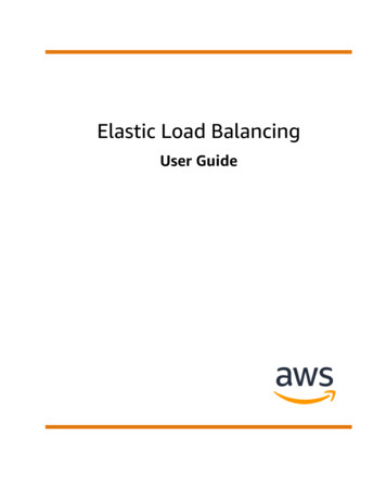
Load Calculation Applications Manual (SI), Second Editionbuilding. The calculation also is critical to professionally answering the first question.Answers to the third question help the designer make choices to improve the performanceor efficiency of the design and occasionally may influence architectural designers regarding energy-sensitive consequences.1.3 Overview of the ASHRAE Load Calculation Methods1.3.1 Models and RealityAll calculation procedures involve some kind of model, and all models are approximate. The amount of detail involved in a model depends on the purpose of that model.This is the reality of modeling, which should describe only the variables and parametersthat are significant to the problem at hand. The challenge is to ensure that no significantaspects of the process or device being modeled are excluded and, at the same time, thatunnecessary detail is avoided.A complete, detailed model of all of the heat transfer processes occurring in abuilding would be very complex and would be impractical as a computationalmodel, even today. However, building physics researchers and practitioners generally agree that certain modeling simplifications are reasonable and appropriateunder a broad range of situations. The most fundamental of these is that the air inthe space can be modeled as well-stirred. This means there is an approximately uniform temperature throughout the space due to mixing. This modeling assumption isquite valid over a wide range of conditions. With that as a basis, it is possible to formulate fundamental models for the various heat transfer and thermodynamic processes that occur. The resulting formulation is called the HBM. There is anintroduction to the general principles of the HBM in Chapter 2 and further description in Chapter 11.1.3.2 The Heat Balance MethodThe processes that make up the heat balance model can be visualized using the schematic shown in Figure 1.1. It consists of four distinct processes:1.2.3.4.Outside face heat balanceWall conduction processInside face heat balanceAir heat balanceFigure 1.1 shows the heat balance process in detail for a single opaque surface. Theshaded part of the figure is replicated for each of the surfaces enclosing the zone.The process for transparent surfaces is similar to that shown but does not have theabsorbed solar component at the outside surface. Instead, it is split into two parts: aninward-flowing fraction and an outward-flowing fraction. These fractional parts participate in the inside and outside face heat balances. The transparent surfaces, of course, provide the transmitted solar component that contributes to the inside heat balance.The double-ended arrows indicate schematically where there is a heat exchange, andthe single-ended arrows indicate where the interaction is one way. The formulation of theheat balance consists of mathematically describing the four major processes, shown asrounded blocks in the figure.1.3.3 The Radiant Time Series MethodThe RTSM is a relatively new method for performing design cooling load calculations. It is derived directly from the HBM and effectively replaced all other simplified(non-heat-balance) methods such as the transfer function method (TFM), the cooling2
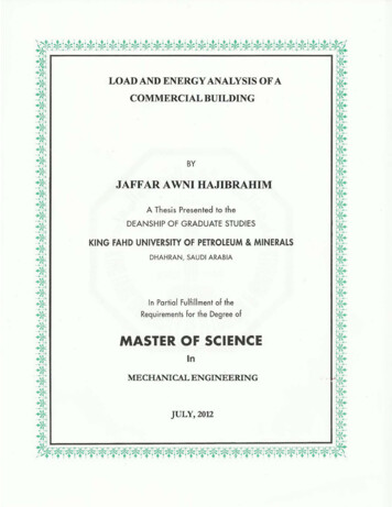
IntroductionFigure 1.1 Schematic of heat balance process in a zone.(Source: Cooling and Heating Load Calculation Principles, Figure 1.1).load temperature difference/solar cooling load/cooling load factor method (CLTD/SCL/CLFM), and the total equivalent temperature difference/time averaging method (TETD/TAM). The RTSM was developed in response to a desire to offer a method that was rigorous yet did not require the iterative calculations of the previous methods. In addition,the periodic response factors and radiant time factors have clear physical meanings;when plotted, they allow the user to visually see the effects of damping and time delayon conduction heat gains and zone response.The utility of the RTSM lies in the clarity, not the simplicity, of the procedure.Although the RTSM uses a “reduced” heat balance procedure to generate the radianttime series (RTS) coefficients, it is approximately as computationally intensive as theheat balance procedure upon which it is based. What the RTS method does offer isinsight into the building physics without the computational rigor of the HBM, a sacrifice in accuracy that is surprisingly small in most cases. Previous simplified methodsrelied on room transfer function coefficients that completely obscured the actual heattransfer processes they modeled. The heat-balance-based RTS coefficients, on theother hand, provide some insight into the relationship between zone construction andthe time dependence of the building heat transfer processes. The RTSM abstracts thebuilding thermal response from the fundamentally rigorous heat balance and presentsthe effects of complex, interdependent physical processes in terms that are relativelyeasy to understand. The abstraction requires a number of simplifying assumptions andapproximations. These are covered in Section 7.1. Figure 1.2 shows the computationalprocedure that defines the RTSM. A more detailed schematic is shown in Chapter 7.In the RTSM, a conductive heat gain for each surface is first calculated using air-toair response factors. The conductive heat gains and the internal heat gains are then splitinto radiant and convective portions. All convective portions are instantaneously convertedto cooling loads and summed to obtain the fraction of the total hourly cooling load causedby convection.3
Load Calculation Applications Manual (SI), Second EditionFigure 1.2 Schematic of the radiant time series method.(Source: Cooling and Heating Load Calculation Principles, Figure 1.2).Radiant heat gains from conduction, internal sources, and solar transmission are operated on by the RTS to determine the fraction of the heat gain that will be converted to acooling load in current and subsequent hours. These fractional cooling loads are added tothe previously calculated convective portions at the appropriate hour to obtain the totalhourly cooling load.1.4 Organization of the ManualThis manual is organized to roughly proceed from the general to the specific.Chapter 2 provides an overview of the heat transfer processes present in buildings and abrief discussion of how they are analyzed together in order to determine the building cooling load. Chapters 3–6 cover thermal properties, design conditions, infiltration, and internal heat gains—all of which are relevant to all load calculation methods. Chapters 7 and 8cover the theory and application of the RTSM. Chapter 9 covers systems and psychrometrics, analyses of which are necessary to determine equipment sizes. Chapter 10 considersheating load calculations. Chapter 11 covers the HBM and its implementation.Throughout the manual, numerous shaded examples are presented to illustrate various aspects of the RTSM. A number of the examples are performed using spreadsheetsthat are included in the supporting files online at www.ashrae.org/lcam.ReferencesPedersen, C.O., D.E. Fisher, J.D. Spitler, and R.J. Liesen. 1998. Cooling and HeatingLoad Calculation Principles. Atlanta: ASHRAE.4
2Fundamentals of Heat Transfer and Thermodynamicshe cooling load is defined as the amount of heat that must be removedfrom the room air to maintain a constant room air temperature. Conversely, the heating load is the amount of heat that must be added to theroom air. To determine these quantities, it is necessary to estimate theheat transmission into or out of the room. In turn, this requires analysis ofall three modes of heat transfer—conduction, convection, and radiation— within thebuilding envelope and between the building envelope and its surroundings. (Here, theterm building envelope refers to the walls, roofs, floors, and fenestrations that makeup the building.)The three modes of heat transfer all occur simultaneously, and it is the simultaneous solution of all three modes of heat transfer that complicates the analysis. In practice,this simultaneous solution is done with a computer program either during the load calculation procedure (e.g., the heat balance method [HBM]) or prior to the load calculation procedure (all simplified load calculation procedures rely on tabulated factors thatwere developed with a simultaneous solution of all three modes of heat transfer).Before concerning ourselves with the simultaneous solution, we should first consider the three modes independently. For convection and radiation, the treatment ofthe individual modes of heat transfer does not go far beyond what is taught in a firstundergraduate course1 in heat transfer. For steady-state conduction heat transfer, asused in heating load calculations, this is also the case. For transient conduction heattransfer, as used in cooling load calculations, the derivation of the solution procedurecan be somewhat complex, although its application, in practice, is not very difficult.Each of the three modes is discussed briefly below. Then, after considering thethree modes of heat transfer, the simultaneous solution—based on the first law ofthermodynamics—is briefly discussed.T2.1 Conduction—Steady StateHeat transfer through building walls and roofs is generally treated as a pureconduction heat transfer process, even though, for example, convection and radiation may be important in an internal air gap2 in the wall. Conduction is the transfer of heat through a solid3 via random atomic and molecular motion in responseto a temperature gradient. Elements of the building envelope such as thermalbridges and corners distort the temperature gradients so that the heat flows indirections other than purely perpendicular to the envelope surfaces. Such heatflow is said to be multidimensional. For building load calculations, multidimensional conduction heat transfer is generally approximated as being one-dimensional; however, the approximations do take into account the impact of thermalbridges.4 Heat loss from foundation elements is also multidimensional, but again,approximations are made that simplify the calculation procedure.1.2.3.4.Cf. Incropera and DeWitt (2001).Even though heat transfer in an air gap is due to convection and radiation, it is approximated as beinga conduction process with a fixed thermal resistance that is independent of the temperatures of thegap surfaces.Technically, conduction also occurs in liquids and gases, too. But here we are only concerned with conduction in solids.Appendix E covers the treatment of thermal bridges.5
† TC 4.1 and TC 5.10, Kitchen Ventilation, and their contractors (RP-1326) have produced a complete new data set on heat gains from kitchen equipment based on experimental measurements. † TC 4.2, Climatic Information, and their contractors have produced new weather data (RP-1613) for o