Transcription
Too Many Package Options: WhatMakes Sense for Your Application?E. Jan Vardaman, President andFounder 2021 TechSearch International, Inc.
Unprecedented Era of Change for Packaging Economic advantage of silicon scaling is gone– High cost of moving to next silicon node– High cost of fabrication includes design, mask, and fab process– Only a limited number of foundries can afford to participate forthe limited number of companies at advanced nodes Heterogeneous integration provides an opportunity to achieveeconomic advantages lost with end of pure silicon scaling– Many options for the package including silicon interposers, FO onsubstrate, chiplets, and variations of 3D stacking Heterogeneous integration offers improved SI, PI, lowerinductance and thermal resistance, form factor advantages– Co-design of silicon and package essential– Thermal issues must be addressed– Material selection is important 2021 TechSearch International, Inc.
High-Performance Packaging: Drives the New Era Markets– Networking, data centers, AI/accelerators, machine learning, gaming, 5Ginfrastructure, edge computing Key performance metrics driving the adoption of Si interposer, 3D, andHDFO– Low latency– Bandwidth & data rate increase (GHz, Gbps)– Better power efficiency (pJ/bit) and improved power delivery– Routing density increase (# of lanes per mm/layer)– IO density (IO/mm2) Cost Drivers– Si partitioning in advanced nodes– Reuse of IP for time to market & reduction in cycle time 2021 TechSearch International, Inc.
Many Different Packaging Options Silicon Interposers– Xilinx (many FPGA products) started in 2012, AMD shipped in 2015 (GPU HBM),NVIDIA (GPU HBM), Google, Baidu, Broadcom, many others in production! Fan-Out on SubstrateSource: NVIDIA.– Chip first (in production since 2016 at ASE) and chip last solutions (many designs)– In production for network switch at TSMC with InFO oS (since 2018)– Amkor Substrate-SWIFT , SPIL Fan-Out Embedded Bridge, TFME Embedded bridge Intel, IBM, SPIL, TSMC, and others– Intel’s EMIB silicon bridge in an laminate substrate, embedded by substratesupplier (Intel Stratix 10 for AI accelerator)Source: Intel by TechInsights.– Amkor, ASE, IBM, SPIL, TSMC offerings RDL Interposers InFO-SoIS (System on Integrated Substrate), Samsung R-Cube ,Unimicron, and others– Extend to finer feature (2µm L/S) switch to fab-like process 3D stacking– Memory-on-logic (AMD’s new 3D Vcache, Samsung’s X-Cube) or logic-on-logic(Intel’s Foveros) 2021 TechSearch International, Inc.Source: ASE.
Why Si Interposer? Silicon interposer offers the highestdensity connection– Handle communication between HBM stackand logic (FPGA, GPU, or ASIC)– Communication between logic slices– Most mature, but expensive Logic HBM– Early HBM stacks of 4 DRAM logic layer,now stack with 8 DRAMs common, future 12Source: Xilinx. 2021 TechSearch International, Inc.
TSMC’s Silicon Interposer Solution Increasing size of interposer and multiple HBMs drives the size of the laminate substrate that forms the package– Package body sizes of 65 mm x 65 mm, 75 mm x 75 mm, increasing to 100mm x 100mm body size– Applications include AI accelerators, FPGAs, network switch, GPUs 2021 TechSearch International, Inc.
NVIDIA’s GPU HBM NVIDIA’s GPU with 4 HBMs (8 high stack logic layer) mounted on Si interposer– HBM with wide bus (1,024 I/Os, 4,000 bumps,55µm micro bump pitch) NVIDIA’s latest A100 uses GPU 6 HBMs– Continues to use CoWoS processSource: NVIDIA. 2021 TechSearch International, Inc.
Samsung I-Cube Silicon Interposer Samsung’s silicon interposer ispart of its “cube” family ofpackages– Demonstrated a 2,500mm2 siliconinterposer for up to 2 logic die plus8 HBMs in an 85mm x 85mmpackage– Qualification for 2,800mm2 siliconinterposer is underwaySource: Samsung. 2021 TechSearch International, Inc.
Why Fan-Out on Substrate Solutions? Fan-out on substrate applications inproduction for split die Many designs for HBM logic underinvestigation with productionexpected in 2022-23 Advantages of fan-out on substratetechnology– Lower cost than Si interposer– Potential for larger size packages thanwith Si interposer because there is lesswarpage– RDL with polyimide has CTE closer tothat of the package substrate, resultingin lower residual stress at the packagelevelSource: TechSearch International, Inc., MediaTek. 2021 TechSearch International, Inc.
ASE’s FOCoS (Fan-Out Chip on Substrate) Applications include networkswitch, GPU, AI– In production since 2016 for split die fornetwork switch ASE chip first or chip last– 2µm L/S– Up to 4 RDLsSource: ASE. 2021 TechSearch International, Inc.
Amkor’s Substrate-SWIFT Amkor’s chip last FOversion– 2µm L/S– 4 RDLs qualified– 6 RDLs to be qualified byend of 2021 2021 TechSearch International, Inc.
Why Embedded Bridge Solutions? Advantages of embedded bridge technology– Only use high-density connection where required– Potential for lower cost with reduced number ofRDLs with FO RDL versions– Improved electrical performance Many companies offer embedded bridge solutions––––––Amkor (embedded in RDL, chip last)ASE (embedded in RDL, chip last)IBM (embedded in laminate substrate trench)Intel (embedded in laminate substrate)SPIL (embedded in RDL, chip last)TSMC (embedded in RDL for FO, embedded withSi interposer-CoWoS)Intel’s Embedded Multi-die Interconnect Bridge (EMIB) 2021 TechSearch International, Inc.Source: ASE.
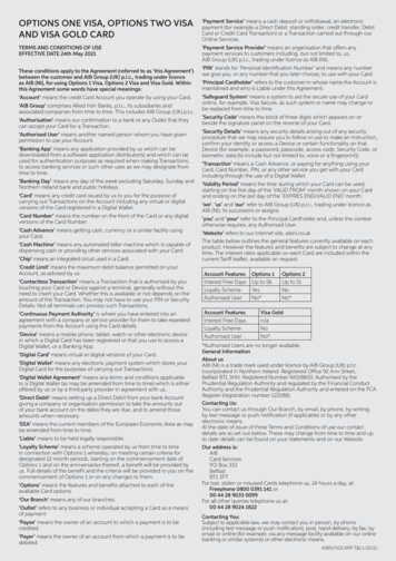
Intel’s Embedded Multi-die Interconnect Bridge (EMIB)EMIB size compared to grain ofBasmati riceSource: Intel.Source: TechInsights. A small silicon bridge chip is embedded into the package (no TSVs) to provide in-package, highdensity connection– Micro bumps on chips, communication between chips through bridge die– Bridge die, designed and fabricated by Intel, embedded in the laminate substrate by substratesupplier Provides a high-density localized interconnect between the FPGA and HBM, density ranges from 250to 1,000 IO/mm/layer Applications include FPGA, discrete GPU, AI, server, and other data center HPC segments 2021 TechSearch International, Inc.
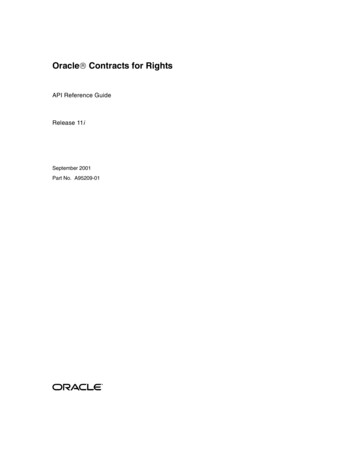
IBM Direct Bonded Heterogeneous Integration (DBHi) Si BridgeNCPThermal Interface MaterialUnderfillTrenchLid adhesiveOrganic LaminateLidChip 1C4Cu PillarsChip 2Si BridgeChip 2Chip 1NCPLaminate FC layersBridgeBridgeCu pillarsNCPC4underfillC4sTrenchLaminate core 2021 TechSearch International, Inc.Source: IBM.
SPIL FO-EB TechnologySource: SPIL. SPIL has qualified a fan-out embedded bridge (FO-EB) RDL test vehicle– Microbumps used to connect each die to RDL– C4 bumps connect to next level FO-EB targeted for CPU HBM, GPU, and networking 2021 TechSearch International, Inc.
Samsung R-Cube RDL Interposer R-Cube is RDL interposer for logic HBM– Up to 4 layers have been fabricated– The 8mm x 12mm HBM2 has a 55µm minimum pitch– Test vehicle package is 55 mm x 55 mm 2021 TechSearch International, Inc.Source: Samsung.
TSMC InFO System on Integrated Substrate (SoIS)Source: TSMC. High-density heterogeneous package using an RDL interposer with up to 6 interconnection layers– Alternative to large, high-density substrates where yield and power consumption are challenges Good electrical performance (large eye height, low jitter, and almost no layer-to-layer crosstalk),lower insertion loss 2021 TechSearch International, Inc.
New Era of Semiconductor Packaging Chiplets will be a key enabler for next 10-20 years 2021 TechSearch International, Inc.Source: Overclock3d.net.
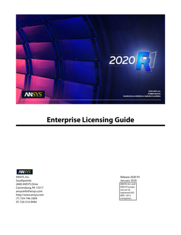
Die Size Growth: Major Driver for Adoption of Chiplets Die sizes continued toincrease over time forserver CPU and GPUDie Size Increases over Time1000– nVIDIA’s 826 mm2 die,fabricated at TSMC, is one ofthe largest in productiontoday– Samsung reports die sizes of750 mm2 Performance requires moretransistors, but industryneeds a new, moreeconomical approachReticle Limit100Oct-06Jul-09Apr-12– Smart packaging, includingheterogeneous integrationand chiplets becomes theanswerDec-14Server CPUGPUSep-17Jun-20Source: AMD internal analysis. 2021 TechSearch International, Inc.Mar-23
Many Drivers for Chiplet AdoptionMix and matchnew SKUsDisaggregation benefits includeoptimization node per chipletSmaller die higher yield (moredie per wafer)allow optimizedcost per chipletImproved powerefficiency (goal of0.5pJ/bit)Chiplets can be binnedand speed sorted,allowing optimalperformance and saleof more chipletsFiner bump or pad pitch higher density 2021 TechSearch International, Inc.Stitchtogether tocreate 1Xreticleproducts
How Do We Define Chiplets? A chiplet is an integrated circuit block specifically designed to work with other chipletsto form a larger more complex system that often makes use of reusable IP blocks– A chiplet can be created by partitioning a die into functions that are more cost effectivelyfabricated (smaller die, higher yield, and less advanced nodes)– A chiplet is a hard IP block– Functions with other chiplets, so design must be co-optimized and silicon cannot be designed inisolation– Made possible by communication using chiplet interface (proprietary today) Differs from SiP or traditional MCM in that it is a new design, not just a combination ofdifferent “off-the-shelf” chips Chiplet is not the package, it’s the design philosophy– Change from “silicon centric thinking” to “system-level planning” and “co-design of IC andpackage”– The industry has to think about chip design in a new way– Same impact as when the industry moved from a peripheral chip layout to area array! 2021 TechSearch International, Inc.
AMD Multiple Chiplet Product Introductions Multiple generations of desktop andserver products using chiplets withorganic substrate– Split out analog functions fromadvanced 7nm logic– Chiplets can be binned and speedsorted before assembly on thesubstrate– Better memory access– Minimize local latency– Power efficiency improvement– 1, 2, 4 or 8 CPU chiplets plus an I/Ochiplet are attached to an organicinterposer 2021 TechSearch International, Inc.Source: Wired.com.
TSMC InFO oS for Chiplets Targets AI, network system, edge computing– Alternative to the laminate MCM packagefor chiplets FO process is a chip-first process– Allows interconnect formation after wafermolding– Multiple layer RDL acts as a stress-bufferlayer, so ELK stress is not a major concern– Process optimized to reduce warpage Demonstration of 2.5x reticle of fan-out(51mm x 42mm) on a 110mm x 110mmsubstrate– Test vehicle that integrates 10 chiplets (2logic 8 I/O die)– 5 RDLs (4 with 2/2µm, 1 with 5/5 µm)– D2D I/O pitch 36 µmSource: TSMC. 2021 TechSearch International, Inc.
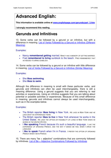
Intel Foveros Technology Intel’s Foveros technology die are stacked in 3D– Base die, using less advanced node, can include power management features, voltage regulators,DC/DC converters Benefits include– Reduced voltage drop– Power efficiency– More immediate power delivery to the CPU cores– Elimination of passives on substrate– System-wide communication across multiple chiplets/dice vs. the limited die-to-die communicationcapability enabled by passive Si interposers Used in the Samsung Galaxy Book S (Mobile PC)– Longer lasting battery– No fan– Very thin package, allows thin productIntel’s Lakefield CPU 10nm CPU 22nm Base dieSource: Intel. 2021 TechSearch International, Inc.
Intel’s Data Center CPU with EMIB Intel’s Sapphire Rapids will be Intel’s first CPUserver for data centers using chiplets– All 4 chiplet die will access shared cache and areconnected using the modular die fabric (MDF)– Any core can talk to other cores on the 4 die andaccess the shared cache across all 4 quadrants aswell as I/O across 4 quadrantsSource: Intel. 2021 TechSearch International, Inc.
Intel Co-EMIB (EMIB Foveros)Source: Intel. EMIB and Foveros can be combined to provide a high-density solution– Connecting HBM and logic with silicon bridge Intel’s data center GPU with 2 large GPU 3D center tiles (Foveros), 8 HBMstacks and 2 additional chips each connected using EMIB 2021 TechSearch International, Inc.
Samsung 3D IC (X-Cube)Source: Samsung. Samsung introduction of logic and memory stack First version with µbump connections 2021 TechSearch International, Inc.
TSMC SoIC Technology First commercial products with SoIC expected in 2021Source: TSMC. Commercial products with up to 10 chiplets expected in 2-3 years Advanced silicon nodes of 7nm or 5nm could be used SoIC could be placed next to HBM on RDL substrate or SoIC could be mounted next toHBM on CoWoS 2021 TechSearch International, Inc.
SoIC Compared to 2.5D and 3D ICSource: TSMC. With SoIC there is virtually no distance between integrated chips, and a very small bond-pad pitch of 9 µmprovides good scalability Using a bumpless bonding process is critical to improvements in performance, power, resistance, and capacitance(lower inductance and thermal resistance) 2021 TechSearch International, Inc.
AMD’s 3D Chiplet AMD’s Prototype 5900Xchip for gaming– Gaming performanceimprovement Same 7nm node asRYZEN, but performancegains using 3D chipletcopper-to-copper hybridbondSource: AMD. 2021 TechSearch International, Inc.
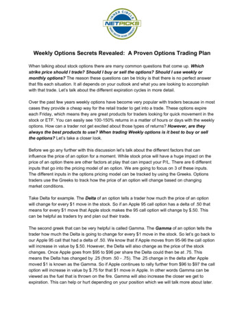
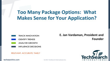
Many Package Options: Which One Do I Choose?3D with µbumpsSource: Samsung.Embedded Silicon BridgeRouting densityrequirementsPower efficiency and power delivery3D with hybrid bondMaturity of technologySource: Intel.Silicon InterposerSupply chainThermal performance needsSource: TSMC.Test considerationsSource: Xilinx.Relative cost vs. alternativesFan-Out on SubstrateProduct life and reliabilityrequirementsSource: ASE.Source: Nvidia. 2021 TechSearch International, Inc.
Thank you!TechSearch International, Inc.4801 Spicewood Springs Road, Suite 150Austin, Texas 78759 USA 1.512.372.8887tsi@techsearchinc.com 2021 TechSearch International, Inc.
– Amkor Substrate-SWIFT , SPIL Fan-Out Embedded Bridge, TFME Embedded bridge Intel, IBM, SPIL, TSMC, and others – Intel’s EMIB silicon bridge in an laminate substrate, embedded by substrate supplier (Intel Stratix 10 fo