Transcription
SERVICE MANUAL AND SPARE PARTS LISTMR EPAIRZF 3 M (HBW 35)ZF 5 M (HBW 50)ZF 10 M (HBW 100)ZF 12 M (HBW 125) / HBW 10ZF 15 M (HBW 150)ZF 15 MA (HBW 150 A)ZF 15 MIV (HBW 150 V)ZF 25 M (HBW 250)ZF 25 MAZF 30 MCod. 310.01.0052fA LUNA
Manual and Spare Parts List ZF M lineThis ZF M manual has been preparedfor all those who have to do with ZFHURTH Marine reversing gearbox unitsof the ZF M line, including models ZF 3M, ZF 5 M, ZF 10 M, ZF 12 M, ZF 15 M,ZF 15 MA, ZF 25 M, ZF 25 MA, ZF 30 M,ZF 15 MIV, in particular for- power plant suppliers- shipyards- craft ownersThe ZF M manual is intended as an aidfor handling ZF M transmissions and willanswer all questions that may arise indaily operation and in connection with theinstallation and repair of ZF M transmissions.This manual contains:- Technical description of the gearboxunits and a number of important technical data;- Instructions for proper installation of thegearbox in the craft;- Explanatory notes on correct operationand maintenance;- Detailed description of all disassemblyand reassembly procedures (withdrawings);- Troubleshooting table with possiblecauses of trouble and the required remedial action;- Spare parts list with stock numbers ofall sparte parts;- Explosion-View drawings showingeach part with the reference numeralsused in the text.No problems will be encountered in handling, installing and operating the ZF Mgearbox if the instructions in this manualare followed. Should a repair be necessary, a qualified technician will have nodifficulty in doing the repair work in accordance with the detailed instructionsgiven on the following pages.In addition, ZF M Service Stations (distributors and dealers) are available forany repairs and for supplying the spareparts required. The manufacturer will always be glad to name the Service Station nearest to your location.All transmission units are covered by aworldwide guarantee given by the manufacturer. The manufacturer’s warrantywill be subject to the condition that:- the instructions in this manual arestrictly observed in handling thetransmission.- no work is performed by persons notauthorized by ZF-HURTH Marine.- no changes or alterations of any kindare made on the transmission.Failure to observe these points willinvalide all and any warranty claims.Caution: never start doing any work onthe transmission unless and until theengine and the propeller have come toa complete standstill.3
Manual and Spare Parts List ZF M lineTable of contents1.1.11.2DescriptionBrief descriptionTechnical data and maindimensions1.2.1 ZF 3 M boat reversinggearbox unit1.2.2 ZF 5 M boat reversinggearbox unit1.2.3 ZF 10 M boat reversinggearbox unit1.2.4 ZF 12 M boat reversinggearbox unit1.2.5 ZF 15 M boat reversinggearbox unit1.2.6 ZF 15 MA boat reversinggearbox unit1.2.7 ZF 15 MIV boat reversinggearbox unit1.2.8 ZF 25 M boat reversinggearbox unit1.2.9 ZF 25 MA boat reversinggearbox unit1.2.10 Accessories1.2.11 Tools1.2.12 Ident. No.1.3Gear casing1.4Gear set1.5Multiple-disc clutch and clutchoperation1.6Shaft bearings1.7Shaft seals1,8Lubrication1.9Cooling ry conditionTransportRemoval of preservativePainting the gearboxConnection of gearboxwith engineConnection of gearboxwith propellerSuspension of enginegearbox assembly in the boatPosition of gearbox inthe boatOperation of gearboxCooling unitEngine-gearbox compartment3.3.13.23.33.43.53.63.7OperationGeneral informationInitial operationOperating temperatureOperation of gearboxSailing or moving in towLay-up periodsPreparation for 06.116.126.136.146.15MaintenanceTransmission oilOil quantityOil level checksOil changeChecking the shift cableand linkageCooling unitAutomatic transmission fluiidList of recommended fluidsDisassemblyRemoving the cooling unitRemoving and disassemblingthe actuating lever cover plateRemoving the bearing shieldsSeparating the gearboxsections and removing theinput and output shaftsRemoving the shifting forkRemoving the intermediate gearDisassembling the input shaftDisassembling the output shaftDisassembling the quill shaftReassemblyGeneral informationPre-assembling the intermediategear shaft in the gearbox sectionwithout openingPre-assembling the shifting forkin the gearbox section withopeningPre-assembling the actuatinglever cover platePre-assembling the gearsMeasuring the pre-assembledgears to determine settingvalue «a»Pre-assembling the bearingshieldsPre-assembling the actuatingmembersReassembling the input shaftReassembling the output shaftReassembling the quill shaftFinal assembly of gearboxMeasuring the gear sets ofinput shaft and output shaftMounting the actuating levercover plateMounting the cooling unit7.Procedure to adjust the shiftinglever cover8.Troubleshooting9.Spare parts list10.Drawings (Explosion view)
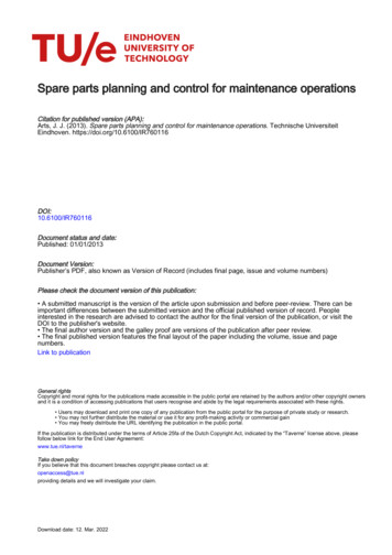
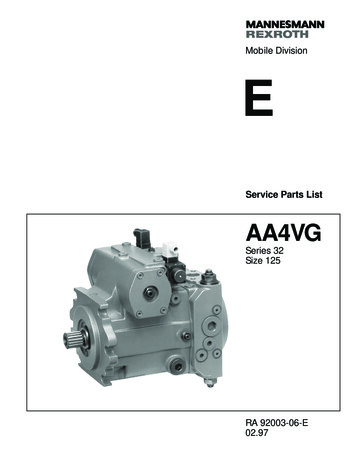
Manual and Spare Parts List ZF M line1.Description1.1Brief descriptionZF-HURTH Marine boat reversing gearbox units of the ZF M line are servo-automatically controlled helical gear transmissions developed for use in pleasurecraft and commercial craft. The servooperated multiple-disc clutchrequires only minimum effort for shifting,making the ZF M transmission suitablefor single-lever remote control via a rodlinkage or shift cable.In emergency situations the ZF M permits direct reversing at engine speedabove idle rpm.The torque capacity of the clutch is exactly rated, preventing shock loads fromexceeding a predetermined value to ensure maximum protection of the engineand thus providing the effect of a safetyclutch.The transmission units are characterizedby low weight and small overall dimensions. The gearbox castings are madeof a high-strength, corrosion-resistantaluminium alloy, chromized for improvedseawater resistance and optimumadhesion of paint.A choice of gear ratios, a high efficiencyrating and low-noise operation are otherprominent features of the ZF M gearboxunits.The transmissions are immersion-lubricated. Maintenance is restricted to oillevel checks (see «Maintenance», chapter 4).Transmission sizes are available forright-hand (RH) and left-hand (LH)rotation of the input shaft, the directionof rotation being specified as seen by anobserver facing the input shaft.In gear lever positions A, the engine shaftand the propeller shaft rotate in opposite directions, in position B in the samedirection (Fig. 1).On model ZF 15 MIV, the directions ofrotation are the other way round (Fig. 2).Engine manufacturers should note thatthe direction of rotation refers to an observer facing the flywheel, so that lefthand rotation of the engine correspondsto right-hand rotation of the gearbox input shaft.The shafts are supported by heavy-dutytaper roller bearings and the gearbox isdesigned to take the axial propeller thrust(for permissible values see «Technicaldata», item 1.2).Fig. 1Fig. 25
Manual and Spare Parts List ZF M line1.2.1 ZF 3 MTransmission power inputTransmission input speed (rpm)Power diagramBased on engine power B to DIN 6270;shock factorK 1.25 to applied, if engine has 1 cylinderK 1.20 for 2 cylindersK 1.15 for 3 cylindersZF 3 M-2 RZF 3 M-3 RShifting position «A»Technical dataratio2.05:12.72:1Shifting position «B»ratio1.86:12.15:1Input torque max.Nm (ft lb)40 (29,5)30 (22,1)Power input max.kW (hp)15 (20)Input speed max.rpm5000Propeller thrust max.N (lb)1000 (225)Weight without fluidkg (lb)8 (17.7)Fluid quantityliter0.3Fluid gradeAutomatic-Transmission-Fluid (ATF)6
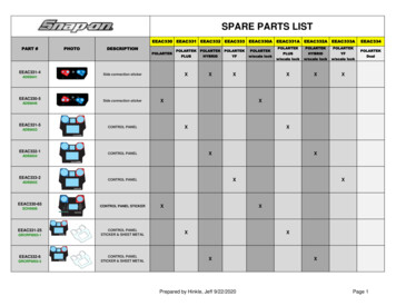
Manual and Spare Parts List ZF M lineFig. 3 ZF 3 M54All dimensions in mm7
Manual and Spare Parts List ZF M line1.2.2 ZF 5 MTransmission power inputPower diagram for Pleasure Craft DutyBased on engine power B to DIN 6270;shock factorK 1.25 to applied, if engine has 1 cylinderK 1.20 for 2 cylindersK 1.15 for 3 cylindersMODELRATIO«A» PosPOWER / RPM«B»PoskWhpINPUT POWER CAPACITYkWhp2800 rpmZF 5 518kWhp kW3000 rpm20142719MAXhpWEIGHTBELL HSGS.RPMkglbAND NOTES50005000818B/WMax input power 20 kW3600 rpm20172723«A» POS continuous running position (normally AHEAD).«B» POS reverse position.B/W Borg Warner adaptor.Note For all «M» (Mechanical) transmission reduce power capacity by the following schock factors: 1 cylinder engine 1.25, 2 cylinder engine 1.20,3 cylinder engine 1.15.8
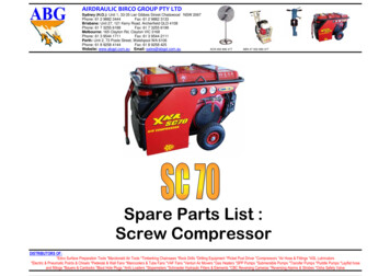
Manual and Spare Parts List ZF M lineFig. 4 ZF 5 M54All dimensions in mm9
Manual and Spare Parts List ZF M line1.2.3 ZF 10 M1,8Transmission power inputTransmission input speed (rpm)Power diagram for Pleasure Craft DutyBased on engine power B to DIN 6270;shock factorK 1.25 to applied, if engine has 1 cylinderK 1.20 for 2 cylindersK 1.15 for 3 cylinders** Max. 95 Nm (70 ft lb) admissible for main travelling direction with gearlever set to «B»MODELRATIO«A» PosPOWER / RPM«B»PoskWhpINPUT POWER CAPACITYkWhp2800 rpmZF 10 M1.4821.7922.0452.7221.8641.8641.8642.150kWhp kW3000 rpmMAXhpWEIGHTBELL HSGS.RPMkglbAND NOTES9.521SAE 4, 5, B/WMax input power 38 kW.Ratio 1.482 «B» Pos.max torque 95 Nm. Ratio1.792 «B» Pos. maxtorque 95 Nm.3600 .009127193626292038273425463350005000«A» POS continuous running position (normally AHEAD).«B» POS reverse position.B/W Borg Warner adaptor.Note For all «M» (Mechanical) transmission reduce power capacity by the following schock factors: 1 cylinder engine 1.25, 2 cylinder engine 1.20,3 cylinder engine 1.15.10
Manual and Spare Parts List ZF M lineFig. 5 ZF 10 M54All dimensions in mm11
Manual and Spare Parts List ZF M line1.2.4 ZF 12 MTransmission power inputTransmission input speed (rpm)Power diagram for pleasure craftBased on engine power B to DIN 6270;shock factor K 1.25 to applied,if engine has fewer than 4 cylinders.MODELRATIO«A» PosPOWER / RPM«B»PoskWhpINPUT POWER CAPACITYkWhp2800 rpmZF 12 942kWhp kW3000 rpm39335345MAXhpWEIGHTBELL HSGS.RPMkglbAND NOTES500050001329SAE 4, 5, B/WMax input power 55 kW3600 rpm47406354«A» POS continuous running position (normally AHEAD).«B» POS reverse position.B/W Borg Warner adaptor.Note For all «M» (Mechanical) transmission reduce power capacity by the following schock factors: 1 cylinder engine 1.25, 2 cylinder engine 1.20,3 cylinder engine 1.15.12
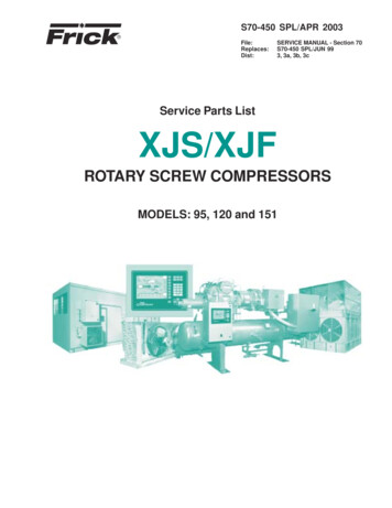
Manual and Spare Parts List ZF M lineFig. 6 ZF 12 MModel without mounting flangea) Clockwise rotation b) Oil dipstick and filter screw 17 mm c) M 8/12 deep, holes same on both sides d) Oil drain plug 17 mm widthacross flats e) Spline profile similar B 10 x 23 x 29 DIN 5464 f) Minimum lever travelAll dimensions in mmModel with mounting flange13
Manual and Spare Parts List ZF M line1.2.5 ZF 15 MTransmission power inputTransmission input speed (rpm)Power diagram for Pleasure Craft DutyBased on engine power B to DIN 6270;shock factorK 1.25 to applied, if engine has 1 cylinderK 1.20 for 2 cylindersK 1.15 for 3 cylinders** Max. 120 Nm (88.5 ft lb) admissible for main travelling directionwith gear lever set to «B»MODELRATIO«A» PosPOWER / RPM«B»PoskWhpINPUT POWER CAPACITYkWhp2800 rpmZF 15 M1.5561.8751.9551.9550.01520.02044357kWhp kW3000 rpm4661MAXhpWEIGHTBELL HSGS.RPMkglbAND NOTES50001329 SAE 4, 5, B/W, Yanmar JH3600 rpm5573Max input power 55 kW.Ratio 1.556 «B» Pos.max torque 120 Nm.Ratio 1.875 «B» Pos.max torque 120 Nm.«A» POS continuous running position (normally AHEAD).«B» POS reverse position.B/W Borg Warner adaptor.Note For all «M» (Mechanical) transmission reduce power capacity by the following schock factors: 1 cylinder engine 1.25, 2 cylinder engine 1.20,3 cylinder engine 1.15.14
Manual and Spare Parts List ZF M lineFig. 7 ZF 15 MAll dimensions in mm15
Manual and Spare Parts List ZF M line1.2.6 ZF 15 MATransmission power inputGearbox input speed (1/min)Power diagram for Pleasure Craft DutyBased on engine power B to DIN 6270;shock factorK 1.25 to applied, if engine has 1 cylinderK 1.20 for 2 cylindersK 1.15 for 3 cylinders** Max. 120 Nm (88.5 ft lb) admissible for main travelling directionwith gear lever set to «B»MODELRATIO«A» PosPOWER / RPM«B»PoskWhpINPUT POWER CAPACITYkWhp2800 rpmZF 15 MA8 .01110.02040.01760.0149433731574942kWhp kW3000 rpm463933615345MAXhpWEIGHTBELL HSGS.RPMkglbAND NOTES5000500050001329 SAE 4, 5, B/W, Yanmar JH3600 rpm554740736354Max input power 55 kW.Ratio 1.875 «B» Pos.max torque 120 Nm.Ratio 2.136 «B» Pos.max torque 120 Nm.«A» POS continuous running position (normally AHEAD).«B» POS reverse position.B/W Borg Warner adaptor.Note For all «M» (Mechanical) transmission reduce power capacity by the following schock factors: 1 cylinder engine 1.25, 2 cylinder engine 1.20,3 cylinder engine 1.15.16
Manual and Spare Parts List ZF M lineFig. 8 ZF 15 MAModel without mounting flangea) Clockwise rotation b) Oil dipstick and filter screw 17 mm c) M 8/12 deep, holes same on both sides d) Oil drain plug 17 mm width across flats e) Spline profilesimilar B 10 x 23 x 29 DIN 5464 f) Minimum lever travel g) Support for control cable h) full profileAll dimensions in mmModel with mounting flange17
Manual and Spare Parts List ZF M line1.2.7 ZF 15 MIVTransmission power inputTransmission input speed (rpm)Power diagram for Pleasure Craft DutyBased on engine power B to DIN 6270;shock factorK 1.25 to applied, if engine has 1 cylinderK 1.20 for 2 cylindersK 1.15 for 3 cylinders* Max. 120 Nm (88.5 ft lb) admissible for main travelling direction withgear lever set to «B».** Max 45 kW for main travelling direction with gear lever set to «B».MODELRATIO«A» PosPOWER / RPM«B»PoskWhpINPUT POWER CAPACITYkWhp2800 rpmZF 15 MIV8 .02040.014943315742kWhp kW3000 rpm46336145MAXhpWEIGHTBELL HSGS.RPMkglbAND NOTES5000500050002044 SAE 4, 5, B/W, Yanmar JH3600 rpm55407354Max input power 55 kW.Ratio 2.134 «B» Pos.max tor
Should a repair be neces-sary, a qualified technician will have no difficulty in doing the repair work in ac-cordance with the detailed instructions given on the following pages. In addition, ZF M Service Stations (dis-tributors and dealers) are available for any repairs and for supplying the spare parts required. The manufacturer will al-ways be glad to name the Service Sta-tion nearest to .