Transcription
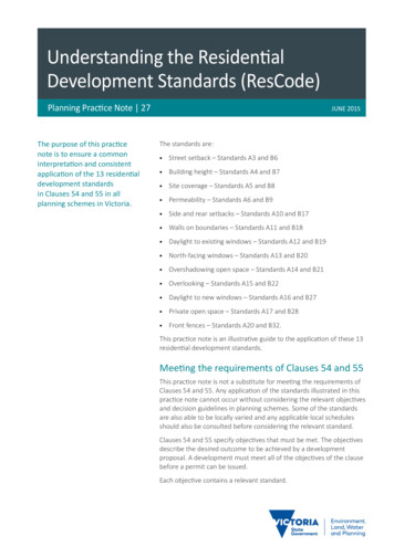
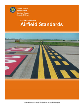
Federal AviationAdministrationSouthern RegionAirports DivisionA Quick Reference toAirfield StandardsThis January 2018 edition supersedes all previous editions
Table of ContentsChapter 1 - Airfield Markings . 1Removal of Markings . 1Use of Glass Beads . 4Use of Black Borders . 4General Guidelines for Determining Light-Colored Pavements . 5Runway Marking Elements . 6Groupings of Touchdown Zone Markings Required When Installed From One Threshold . 7Groupings of Touchdown Zone Markings Required When Installed From Both Thresholds . 8Runway Threshold Stripes for Standard Runway Widths . 9Runway Marking Dimensions . 10Precision Instrument . 10Non-Precision Instrument . 11Visual . 12Displaced Threshold Markings . 13Taxiway Aligned with a Runway . 14Blast Pad Markings. 15Aligned Taxiway Preceding a Displaced Threshold . 16Blast Pad Preceding a Displaced Threshold . 17Enhanced Taxiway Centerline Marking . 18Dashed Lines at Converging Taxiway Centerlines . 19Enhanced Taxiway Centerlines Intersecting with Holding Position Marking . 20Surface Painted Holding Position Signs for Taxiway Widths Greater Than Thirty Five Feet. 24Surface Painted Holding Position Sign for Taxiway Widths Equal to or Less Than 35 Feet . 25Narrow Taxiway Stacked Surface Painted Holding Position Signs . 26Holding Position Marking Details . 27Chapter 2 – Airfield Lighting . 28Legend and General Notes . 28Runway Edge Light Spacing for High Intensity Runway Lights (HIRLs) . 29Runway Edge Light Spacing for Medium Intensity Runway Lights (MIRLs) . 30Threshold / Runway End Lights Installed with MIRLs . 31Threshold / Runway End Lights installed with HIRLs . 32Runway with a Taxiway at the End . 33Runway with a Blast Pad . 34A Quick Reference to Airfield StandardsUpdated January 2018ii
Lighting for Runway with a Displaced Threshold . 35Normal Runway with Taxiway . 36Lighting for Runway with Displaced Threshold Greater than 700’. 37Lighting for Runway with Displaced Threshold Less than 700’ . 38Lighting for Runway with Stopway . 39Lighting for Runway with Displaced Threshold and Stopway . 40Runway with End Taxiway . 41Lighting for Runway with End Taxiway and Displaced Threshold . 42Color-coding of Exit Taxiway Centerline Lights . 43Taxiway Centerline Lighting Configuration for Acute - Angled Exits. 44Typical Layout for Runway End Identifier Lights (REILs) . 45Chapter 3 – Construction Safety . 46Safety Areas and Work Limits . 46Construction Reminders . 47Construction Barricades. 48Temporary Signs . 49Temporarily Closed Runways . 50Partially Closed Runway . 51Partially Closed Runway . 52Temporary Displaced Threshold . 53Lighting Temporarily Relocated or Displaced Runway Thresholds . 54Temporary Taxiway Closure . 55Chapter 4 - Fuel Fire Safety. 56Fueling Supervisor and Personnel Training . 57Fuel Training Certificates . 57Sample Fueling Supervisor Training Certificate . 57Sample Checklist- Fuel Vehicles . 58Sample Checklist- Fuel Farm . 59Sample Checklist- Self-Serve. 60Chapter 5 - Wildlife . 61Chapter 6 - Aircraft Rescue and Fire Fighting (ARFF) . 62ARFF Vehicles . 62ARFF Training. 63Chapter 7 - Pedestrians and Ground Vehicles . 64Chapter 8 – References. 65A Quick Reference to Airfield StandardsUpdated January 2018iii
PURPOSEThis publication provides a quick reference to several FAA standards as detailed in current FAA AdvisoryCirculars (ACs) as of the date of this publication. This guide is not all-inclusive and the applicable ACs shouldbe consulted for information that is more comprehensive.Cover photo – Nashville International Airport (BNA)A Quick Reference to Airfield StandardsUpdated January 2018iv
Chapter 1 - Airfield MarkingsChapter 1 - Airfield MarkingsReference: AC 150/5340-1LRemoval of MarkingsPhysically remove pavement markings that are no longer needed. Do not just paint over them. This prevents acontinued visual appearance of the removed markings.Markings to be removedA Quick Reference to Airfield StandardsMarking removal patternUpdated January 20181
Chapter 1 - Airfield MarkingsChevron markings to be physically removedPatterns for physically removing the chevron markingsA Quick Reference to Airfield StandardsUpdated January 20182
Chapter 1 - Airfield MarkingsMarkings to be physically removedPatterns for physically removed markings plus relocated runway holding position and surfaced painted holdingposition markingsA Quick Reference to Airfield StandardsUpdated January 20183
Chapter 1 - Airfield MarkingsUse of Glass BeadsWhere RequiredWhere Recommended Runway designation Runway edge markings Runway and taxiwaycenterline Taxiway edge markings Displaced threshold markings Threshold markings and bar Demarcation bar Aiming point marking Touchdown zone All holding position markings Geographic position markings Surface painted signs Non-movement area boundarymarkingsNote: Glass beads are not to be used in black paint.Type III beads shall not be applied to red or pink paintUse of Black BordersBlack borders are required on all “light” colored pavements (including fading asphalt). The table on the nextpage has guidelines for determining light-colored pavements.Where Required Where RecommendedAll holding position markingEnhanced Twy centerlinesNon-movement area boundarymarkingsSMGCS Twy centerlinesSurface painted holding signsIntermediate holding positionGeographic position marking(see AC150/5340-1L, 4.11(d))All runway markings except edgemarkingsA Quick Reference to Airfield Standards Taxiway centerlinesTaxiway edge markingsChevronsShoulder markingsUpdated January 20184
Chapter 1 - Airfield MarkingsGeneral Guidelines for Determining Light-Colored PavementsPaint a Black BorderAge of Pavement SurfacePavement Surface TypeNewUp to 2 years oldOver 2 years oldPortland Cement ConcreteYesYesYesAsphalt ConcreteNoNoYesAsphalt TreatedNoNoYesThis table serves only as a general guide since an existing asphalt pavement at one airport locationmay not experience the same rate of surface color deterioration as at another airport location.A Quick Reference to Airfield StandardsUpdated January 20185
Chapter 1 - Airfield MarkingsRunway Marking ElementsThreshold Approach CategoryVisual ApproachNon-precisionApproach(Approaches withvertical guidance notlower than 0.75statute mile visibility)Precision Approach(Approaches withvertical guidancelower than 0.75statute mile visibility)Landing edRequiredRequiredThresholdNote 1RequiredRequiredAiming PointNote 2Note 3Required(not applicable)(not applicable)RequiredNote 4Note 4RequiredRunway Surface MarkingSchemeRunway diagramTouchdown ZoneEdge MarkingsNotes:1. Required on runways serving approach categories C and D airplanes and for runways used, orintended to be used by international commercial air transport.2. Required on 4,200 foot or longer runways serving approach categories C and D airplanes.3. Required on 4,200 foot or longer instrumented runways.4. Used when the full runway pavement width may not be available for use as a runway.A Quick Reference to Airfield StandardsUpdated January 20186
Chapter 1 - Airfield MarkingsGroupings of Touchdown Zone MarkingsRequired When Installed From One ThresholdDistance Between Thresholds(or displaced thresholds)(Feet)6,065 or greater(Note 1)Markings for PrecisionApproach End (includesdisplaced threshold)Other Runway EndVisual or Non-precisionFull set of markingsAiming point markings5,565 - 6,064Less one grouping of rectangularbar markings (Note 2)Aiming point marking5,065 - 5,564Less two groupings of rectangularbar markingsAiming point marking4,565 - 5,064Less three groupings ofrectangular bar markingsAiming point markingNotes:1. Derive the value of 6,065 feet as follows:a. For the non-precision or visual runway end, the table assumes the 900 foot “no marking zone”criterion plus the length of a preferred aiming point marking, which starts 1,020 feet from thestart of the threshold to obtain a length of 1,920 feet.b. Add to this the length of the aiming point marking. The length of the aiming point marking iseither 150 or 100 feet. This table uses a length of 150 feet because all the entries in column 1are greater than 4,200 feet. Therefore, adding 150 feet to 1,920 feet obtains a length of 2,070feet. For the precision end, which equals 3,995 feet, it assumes the 900 foot “no marking zone”followed by the standard 75-foot long rectangular bar for a total length of 975 feet.c. Add to this value the full 3,000-foot touchdown zone marking scheme and the 20-footseparation between the actual starting point of the runway threshold (or displaced threshold)and the bottom edge of the threshold marking to obtain 3,995 feet.d. Summing the values 3,995 and 2,070 yields 6,065 feet.2. Each reduction in a pair of rectangular bar markings from the precision end equates to a 500-footreduction between the thresholds.The painting rationale for this table is to ignore the midpoint between the thresholds so the precisioninstrumented landing is favored over non-precision or visual landings.The length of the non-precision or visual side of the runways always remains at 2,070 feet in length to promotethe painting a full set of touchdown zone markings.A Quick Reference to Airfield StandardsUpdated January 20187
Chapter 1 - Airfield MarkingsGroupings of Touchdown Zone MarkingsRequired When Installed From Both ThresholdsDistance Between Thresholds(or displaced thresholds)(Feet)Markings for Each Threshold(or displaced threshold)7,990 or greater (Note 1)Full set of markings6,990 - 7989Less one grouping of rectangular bars from eachside nearest to the runway midpoint (Note 2)5,990 - 6,989Less two groupings of rectangular bars from eachside nearest to the runway midpoint (Note 2)4,990 - 5,989Less three groupings of rectangular bars from eachside nearest to the runway midpoint (Note 2)Notes:1. The value of 7,990 feet is derived as follows:a. Proceed from the runway midpoint in one direction and you will have the 900-foot “no markingzone” criterion followed by the standard 75-foot long rectangular bar for a total length of 975feet.b. Add to this value the full 3000-foot touchdown zone marking scheme plus the 20-footseparation between the actual starting point of the runway threshold (or displaced threshold)and the edge of the threshold marking to obtain 3,995 feet.c. Double this value for both directions to obtain 7,990 feet.2. Each reduction in a pair of rectangular bar markings from both sides equates to a 1,000-foot reductionbetween the thresholds.The painting rationale for this table is to preserve the midpoint between the thresholds, thereby promoting anequal treatment of painting pairs of rectangular bar markings for both sides.A Quick Reference to Airfield StandardsUpdated January 20188
Chapter 1 - Airfield MarkingsRunway Threshold Stripes for Standard Runway WidthsRunway widthNumber of stripes60 feet475 feet6100 feet8150 feet12200 feet16150-foot-wide runwayA Quick Reference to Airfield StandardsUpdated January 20189
Chapter 1 - Airfield MarkingsRunway Marking DimensionsPrecision InstrumentRunway marking100’ Wide150’ Wide200’ 120’Lx36”WEdge36” wide36” wide36” wideThreshold Bar10’ wide10’ wide10’ x4’W75’Lx6’W75’Lx6’W3’ wide3’ wide3’ wideDesignationCenterline (note 1)Threshold MarkingsAiming PointTouchdown ZoneDemarcation (note 2)Notes:1. Gaps are 80 feet in length. Adjustments to the length of the stripes and gaps, where necessary toaccommodate the runway length, are made near the runway midpoint.2. A demarcation bar delineates a runway with a displaced threshold from a blast pad, stopway, ortaxiway that precedes the runway and is not usable pavement. A demarcation bar is yellow in color.A Quick Reference to Airfield StandardsUpdated January 201810
Chapter 1 - Airfield MarkingsNon-Precision InstrumentRunway marking100’ Wide150’ Wide200’ 120’Lx18”WEdge (optional) (note 2)36” wide36” wide36” wideThreshold Bar10’ wide10’ wide10’ wideThreshold 75’WAiming Point (note ation (note 4)3’ wide3’ wide3’ wideDesignationCenterline (note 1)Notes:1. Gaps are 80 feet in length. Adjustments to the length of the stripes and gaps, where necessary toaccommodate the runway length, are made near the runway midpoint.2. Used when the full pavement width may not be available as a runway.3. Required on 4,200 feet or longer instrumented runways.Note: Aiming Point markings may be reduced to 100 feet in length for runways under 4200 feet.4. A demarcation bar delineates a runway with a displaced threshold from a blast pad, stopway, ortaxiway that precedes the runway and is not usable pavement. A demarcation bar is yellow in color.A Quick Reference to Airfield StandardsUpdated January 201811
Chapter 1 - Airfield MarkingsVisualRunway100’ Wide150’ Wide200’ 120’Lx12”WEdge (optional) (note 2)36” wide36” wide36” wideThreshold Bar10’ wide10’ wide10’ �WAiming Point (note ation (note 5)3’ wide3’ wide3’ wideDesignationCenterline (note 1)Threshold Markings (note 3)Notes:1. Gaps are 80 feet in length. Adjustments to the length of the stripes and gaps, where necessary toaccommodate the runway length, are made near the runway midpoint.2. Used when the full pavement width may not be available as a runway.3. Required on runways serving approach category C and D airplanes or on runways used byinternational commercial transport.4. Required on runways 4,200 feet or longer used by approach category C and D aircraft. Note: AimingPoint markings may be reduced to 100 feet in length for runways under 4200 feet.5. A demarcation bar delineates a runway with a displaced threshold from a blast pad, stopway, ortaxiway that precedes the runway and is not usable pavement. A demarcation bar is yellow in color.A Quick Reference to Airfield StandardsUpdated January 201812
Chapter 1 - Airfield MarkingsDisplaced Threshold MarkingsA Quick Reference to Airfield StandardsUpdated January 201813
Chapter 1 - Airfield MarkingsTaxiway Aligned with a RunwayA Quick Reference to Airfield StandardsUpdated January 201814
Chapter 1 - Airfield MarkingsBlast Pad MarkingsNotes: Dimensions are expressed in feet (meters). The widths of the stopways and blast pads are not the same. Stopways equal runway width. Blastpads equal runway width plus runway shoulders. 50-foot spacing may be used when length of area is less than 250 feet in which case the first fullchevron starts at the index point (intersection of runway centerline and runway threshold). Chevrons are painted yellow and at an angle of 45 degrees to the runway centerline. Chevron spacing may be doubled if length of area exceeds 1000 feet. For stopways of less than 250 feet in length, only full chevrons are required.A Quick Reference to Airfield StandardsUpdated January 201815
Chapter 1 - Airfield MarkingsAligned Taxiway Preceding a Displaced ThresholdA Quick Reference to Airfield StandardsUpdated January 201816
Chapter 1 - Airfield MarkingsBlast Pad Preceding a Displaced ThresholdNote: Demarcation bars are 3 feet wide and NOT part of the useable pavement. Stopway widthequals runway width. Blast pad width equals runway width plus runway shoulders.A Quick Reference to Airfield StandardsUpdated January 201817
Chapter 1 - Airfield MarkingsEnhanced Taxiway Centerline MarkingNotes: Dashed lines for the enhanced taxiway centerline marking are 6 inches in width and separated by 6inches from the taxiway centerline. This applies to both 6 inch and 12-inch taxiway centerline markings The taxiway centerline markings may be shifted left or right to avoid interference with the taxiwaycenterline lights or lights and their housing can be covered up temporarily during the painting process.A Quick Reference to Airfield StandardsUpdated January 201818
Chapter 1 - Airfield MarkingsDashed Lines at Converging Taxiway CenterlinesNotes: As shown in this case, the V-shaped inner dashes start and stop with the outside 9-foot dashes.However, this may not always be the case for the inner dashes. If the V-shaped are less than 5 feet,they may be omitted. Measurements are taken along the center of the centerline stripe.A Quick Reference to Airfield StandardsUpdated January 201819
Chapter 1 - Airfield MarkingsEnhanced Taxiway Centerlines Intersecting with Holding Position MarkingNote: All measurements are taken along the center of the centerline.A Quick Reference to Airfield StandardsUpdated January 201820
Chapter 1 - Airfield MarkingsNotes:1. Enhancement is tangent to merging curve.2. Enhancement terminates 5 feet (1.5 m) from intersection.A Quick Reference to Airfield StandardsUpdated January 201821
Chapter 1 - Airfield MarkingsNotes: Enhancements less than 150 feet merge (tangent) to the curveEnd enhancement with the last set of full dashesA Quick Reference to Airfield StandardsUpdated January 201822
Chapter 1 - Airfield MarkingsNote: The enhancement terminates 5 feet from the taxiway/taxiway intersection.A Quick Reference to Airfield StandardsUpdated January 201823
Chapter 1 - Airfield MarkingsSurface Painted Holding Position Signs for Taxiway WidthsGreater Than Thirty Five FeetNotes: Dimensions are expressed in feet.A 2-4 feetB 3-10 feetC 9-12 feetInscriptions must have a height of 12 feet; however, the height may be reduced as necessary, tothe minimum height of 9 feet. In special situations, the surface painted marking may be reducedto less than 9 feet in order to fit the marking appropriately. Examples of special situationsinclude taxiways with widths narrower than 75 feet or taiways tha need to display multiplerunway designations with arrows. In all cases, inscriptions follow the Advisory Circular,Appendix A, inscription criteria. All other taxiway entrances to the same runway not needing thereduction are to maintain the 12 foot height dimension. For practicality, the lowest heightreduction is 6 feet. In all cases the dimension D is not reduced.D 15 inchesE 9 feetF 3 feetA Quick Reference to Airfield StandardsUpdated January 201824
Chapter 1 - Airfield MarkingsSurface Painted Holding Position Sign for Taxiway WidthsEqual to or Less Than 35 FeetDimension letter(in image above)Dimension(feet)A2-3B6Notes(none)Inscriptions follow the Advisory Circular, Appendix A, inscriptioncriteria. The size of the sign inscription is scaled to fit taxiways 35 feetor less in width for Airplane Design Group I and II. Reference AC150/5300-13.In special situations the surface marking may be reduced to less than6 feet in order to fit the marking appropriately. Examples of specialsituations include taxiways that need to display multiple runwaydesignations with arrows. In all cases, the inscriptions follow theAdvisory Circular, Appendix A, inscription criteria. All other taxiwayentrances to the same runway not needing the reduction are tomaintain the 6-foot height dimension.For practicality, the lowest height reduction is 3 feet.C7.5 inches(none)Note: The dimensions for the enhanced taxiway centerline are in Figure D-1 of the Advisory Circular. Thespacing between the enhanced taxiway centerline and the surface painted holding position sign is 6-12 inches.A Quick Reference to Airfield StandardsUpdated January 201825
Chapter 1 - Airfield MarkingsNarrow Taxiway Stacked Surface Painted Holding Position SignsNotes:1.Stacked surface painted holding position signs for narrow taxiways.2. The recommended order of appearance is as follows:a. If the “stacked” surface painted holding position signs are for a taxiway that clearly accessesone runway (for example, Runway 14L-32R) before another runway (Runway 18-36), then theorder of appearance is from “bottom up” as shown above.b. If the “stacked” surface painted holding position signs are for a taxiway that equally offersaccess to two or more runways, then follow a “clockwise” order of appearance as viewed for theholding position. Hence, the bottorm surface painted holding position sign is the first runway asviewed from the holding position. This practice follows the signage convention.c. A black border should be painted around all surface painted holding position signs.A Quick Reference to Airfield StandardsUpdated January 201826
Chapter 1 - Airfield MarkingsHolding Position Marking DetailsA Quick Reference to Airfield StandardsUpdated January 201827
Chapter 2 - Airfield LightingChapter 2 – Airfield LightingLegend and General NotesReference: AC 150/5340-30HThe table below shows the lighting color symbols and associated letters that are used in images in the rest ofthis chapter.Symbol andcolor lettersDescriptionRunway threshold / End lightsGreen (G) / Red (R)Runway edge light (see note 3)Yellow (Y) / White (W)Runway edge lightWhite (W)Runway edge light (in-pavement)White (W)Runway threshold / End lightRed (R)Taxiway edge lightBlue (B)Runway edge light at displaced thresholdYellow (Y) / Red (R)Threshold / Runway edge lights at displaced thresholdGreen (G) / Yellow (Y)Runway threshold light with a unidirectional green(G UNI)Notes: Light fixtures for the lights identified in the color code chart are specified in AC 150/5345-46. White lights are shown as black. For an instrument runway, install yellow runway edge lights on the last 2000 ft. or one-half the runwaylength, whichever is less. Pavement markings shown on the drawing in AC 150/5340-30H are for reference only.AC 150/5340-1 describes the detailed marking specifications.A Quick Reference to Airfield StandardsUpdated January 201828
Chapter 2 - Airfield LightingRunway Edge Light Spacing for High Intensity Runway Lights (HIRLs)2’ minimum – 10’ maximum from the runway edge (full strength pavement).Longitudinal Spacing: 200’ maximumAt taxiway and runway intersections:For HIRLs when the gap exceeds 400 feet install an in-pavement fixture to maintain uniform spacing.CAT III operations require uniform spacing from threshold to threshold, not to exceed 200’. Install in-pavementlights at intersections, as needed.A Quick Reference to Airfield StandardsUpdated January 201829
Chapter 2 - Airfield LightingRunway Edge Light Spacing for Medium Intensity Runway Lights (MIRLs)2’ minimum – 10’ maximum from the runway edge (full strength pavement).Gaps between lights on a single side of the runway must not exceed 400 feet.A Quick Reference to Airfield StandardsUpdated January 201830
Chapter 2 - Airfield LightingThreshold / Runway End Lights Installed with MIRLsLegend: ctr centerNote: Install six threshold lights on visual runways.A Quick Reference to Airfield StandardsUpdated January 201831
Chapter 2 - Airfield LightingThreshold / Runway End Lights installed with HIRLsLegend: ctr centerNote: Install eight threshold lights on instrument runways.A Quick Reference to Airfield StandardsUpdated January 201832
Chapter 2 - Airfield LightingRunway with a Taxiway at the EndA Quick Reference to Airfield StandardsUpdated January 201833
Chapter 2 - Airfield LightingRunway with a Blast PadA Quick Reference to Airfield StandardsUpdated January 201834
Chapter 2 - Airfield LightingLighting for Runway with a Displaced ThresholdA Quick Reference to Airfield StandardsUpdated January 201835
Chapter 2 - Airfield LightingNormal Runway with TaxiwayA Quick Reference to Airfield StandardsUpdated January 201836
Chapter 2 - Airfield LightingLighting for Runway with Displaced Thr
Lighting for Runway with a Displaced . as of the date of this publication. This guide is not all-inclusive and the applicable ACs should be consulted for information that is more comprehensive. . Nashville International Airport (BNA) Chapter 1 - Airfield Markings A Quick Reference to Airfield Standards Updated January 2018 1 Chapter 1 .