Transcription
Time-Current Curves1
Protective Device CoordinationProtective Device Coordination StudyDescription: An organized time-current study of protectivedevices from the utility to a device. A comparison of the time it takes protectivedevices to operate when certain levels ofnormal or abnormal current pass throughthem.2
Protective Device CoordinationProtective Device Coordination StudyObjective: Determine the characteristics, ratings, andsettings of overcurrent protective devices Ensure that the minimium, un-faulted load isinterrupted when the protective devicesisolate a fault or overload anywhere in thesystem.3
Protective Device CoordinationProtective Device Coordination StudyResults: Selection of instrument transformers ratios Protective relay characteristics and settings Fuse ratings LV circuit breaker ratings, characteristics, andsettings.4
Protective Device CoordinationProtective Device Coordination StudyFrequency: This study should be revised as new protectiveare added or as existing devices are modified. At a minimum, it is recommended that thisstudy be performed every 5 years.5
Protective Device CoordinationProtective Device Coordination StudyFrequency: This study should be revised as new protectiveare added or as existing devices are modified. At a minimum, it is recommended that thisstudy be performed every 5 years.6
OSHA 1910.334Use of Equipment(b) Electric power and lighting circuits.(1) Routine opening and closing of circuits. Load rated switches,circuit breakers, or other devices specifically designed asdisconnecting means shall be used for the opening, reversing, orclosing of circuits under load conditions. Cable connectors notof the load break type, fuses, terminal lugs, and cable spliceconnections may not be used for such purposes, except in anemergency.7
OSHA 1910.334Use of Equipment(b) Electric power and lighting circuits.(2) Reclosing circuits after protective device operation. After acircuit is de-energized by a circuit protective device, thecircuit protective device, the circuit may not be manuallyreenergized until it has been determined that theequipment and circuit can be safely energized. Therepetitive manual reclosing of circuit breakers orreenergizing circuits through replaced fuses is prohibited.Note: When it can be determined from the design of the circuitand the overcurrent devices involved that the automaticoperation of a device was caused by an overload rather than afault condition, no examination of the circuit or connectedequipment is needed before the circuit is reenergized.Cargill Electrical Team Meeting8
OSHA 1910.334Use of Equipment(b) Electric power and lighting circuits.(3) Overcurrent protection modification. Overcurrentprotection of circuits and conductors may not bemodified, even on a temporary basis, beyond thatallowed by 1910.304(e), the installation safetyrequirements for overcurrent protection.Cargill Electrical Team Meeting9
Time-Current CurvesTransformersCargill Electrical Team Meeting10
Time-Current CurvesCablesThe Time-Current Curvesfor cables are also knownas “Damage” curves.Cargill Electrical Team Meeting11
Time Current CurvesMotorThe Time-Current Curvesfor motors are alsoknown as “Damage”curves.Cargill Electrical Team Meeting12
Time-Current CurvesProtective Relays50 – InstantaneousOvercurrent Relay51 – AC TimeOvercurrent Relay67 – AC DirectionalOvercurrent Relay13
Time-Current CurvesFuses14
Time-Current CurvesFusesFuseRatingWhat would cause afuse to blow?1. Inappropriate Sizing2. Inappropriate Typefor application3. Fault800 A15
Time-Current CurvesFuses16
Time-Current CurvesCircuit Breakers17
Time-Current CurvesCircuit BreakersNo action toleft of curveTrip or clear on andto right of curveAll devices should beconsidered at samevoltage18
Time-Current CurvesCircuit BreakersLong Time(i.e., TOL)Short Time(i.e., motor starts/stops)Instantaneous(i.e., Faults)19
Time-Current CurvesCircuit BreakersCargill Electrical Team Meeting20
Time-Current CurvesCircuit BreakersManufacturerTrip UnitRatingModel No.Fault DutyCargill Electrical Team Meeting21
Time-Current CurvesCircuit BreakersAvailable SettingsLTPU – Long Time PickupLTD - Long Time DelaySTPU – Short Time PickupSTD – Short Time DelayINST – InstantaneousGF – Ground FaultGFD – Ground Fault DelayCargill Electrical Team MeetingLSIG22
Time-Current CurvesCircuit BreakersLTPU SettingCargill Electrical Team Meeting23
Time-Current CurvesCircuit BreakersSTPU SettingCargill Electrical Team Meeting24
Time-Current CurvesCircuit BreakersSTD Setting25
Time-Current CurvesCircuit BreakersINST Setting26
Time-Current CurvesCircuit Breakers27
Time-Current CurvesThermal-Mag BreakersThermal portion(usually fixed)“Mag” portion(usually adjustable)“Mag” Setting –Equates to INST28
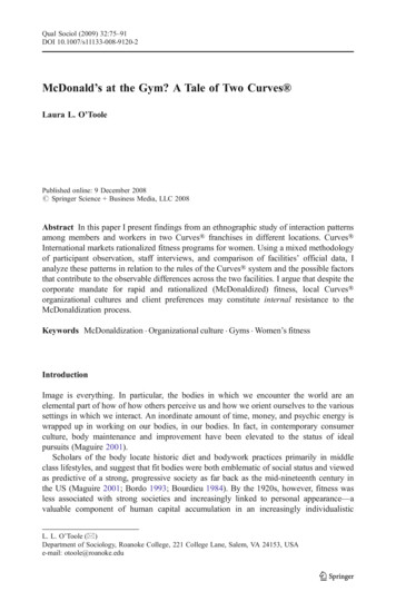
Time-Current CurvesTransformersTransformerProtectionPoint 2500 kVA 2500 kVAANSI17.6 x Ifl x 58%16.6 x Ifl x 58%8 x Ifl12 x Ifl6 x Ifl6 x IflInrush(for 0.1 sec)NEC Rule(6 x Ifl)29
Time-Current CurvesTransformersTransformerInrush must beleft of curve30
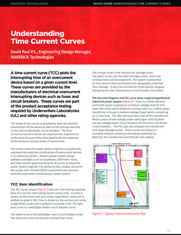
Time Current CurvesMotor ProtectionRefer to NEC Article430.52, “Rating or Settingfor Individual MotorCircuit” and manufacturerrecommendations fordetermining appropriatemotor protection.31
Time Current CurvesMotor Protection32
Time Current CurvesMotor Protection33
Time Current CurvesMotor ProtectionMotor protection relays aretypically programmed to operateapproximately halfway betweenLoad Current Curve and theMotor Damage Curve.34
Time Current CurvesMotor Protection35
Time-Current CurvesQuestions or Comments?36
Troubleshooting37
TroubleshootingTroubleshooting Tools: Design Information: Maintenance Information:— Visual Inspection— One-Line Diagrams— IR Surveys— Time-Current Curves— Oil Sample Reports— Manufacturer Literature— UE/PD Surveys— Operating History— Testing Data Sheets— Protective Relays— Power Monitors38
Troubleshooting Scheduled PM Overdue (Needed Cleaning) High Humidity compounded problem Expulsion Type Fuse failed to operate correctly39
Time-Current CurvesTransformersTransformerInrush must beleft of curve49
TroubleshootingControl PowerTransformer (CPT)Breaker Trip:Cause - Rodent50
TroubleshootingHigh Resistance FuseExtenuatingCircumstances: Inadequate spare parts Production pressureNote: First indicationprovided throughIR Survey.51
TroubleshootingHV Bushing Repair Required Jumpers undersized Heating resulted in gasket failure Oil contamination resulted inflashover at bushing.Note: First indicationprovided throughIR Survey.52
Troubleshooting53
TroubleshootingHV Insulated BusInsulation Tracking(Carbon Treeing)54
TroubleshootingHV Jumper CableInsulation Tracking(Corona Damage Due to Improper Installation)55
TroubleshootingTap ChangerEminent Connection FailureNote: First indication provided through Oil Sampling.56
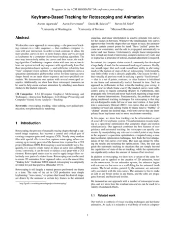
TroubleshootingOctober 2007Event: Fault ( 8,000A) resultedin switchgear lineup burningwithout fuses clearing.XCause: Only one of nine 4/0ground cables was connected.Cable burnedthrough, effectively“protecting” fuse.Cargill Electrical Team Meeting59
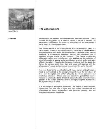
TroubleshootingDecember 2011Event: Fuse (HS0202A) andUtility relay (50/51) cleared,shutting plant down.Cause: TBD.60
TroubleshootingIndicative of Fault61
TroubleshootingIndicative of Fault62
TroubleshootingHS0202A feeds the following:TH0202B thru HS0202B (65A)TH0202C thru HS0202C (100A)TH0202D thru HS0202D (100A)TH0202E thru HS0202E (200A)Apparent fault onB and/or C phasebelow HS0202AX63
OSHA 1910.334Use of Equipment(b) Electric power and lighting circuits.(2) Reclosing circuits after protective device operation. After acircuit is de-energized by a circuit protective device, thecircuit protective device, the circuit may not be manuallyreenergized until it has been determined that theequipment and circuit can be safely energized. Therepetitive manual reclosing of circuit breakers orreenergizing circuits through replaced fuses is prohibited.Note: When it can be determined from the design of the circuitand the overcurrent devices involved that the automaticoperation of a device was caused by an overload rather than afault condition, no examination of the circuit or connectedequipment is needed before the circuit is reenergized.64
TroubleshootingQuestions or Comments?65
Transformer Protection Point 2500 kVA 2500 kVA ANSI 17.6 x I fl x 58% 16.6 x I fl x 58% Inrush (for 0.1 sec) 8 x I fl 12 x I fl NEC Rule (6 x I fl) 6 x I fl 6 x