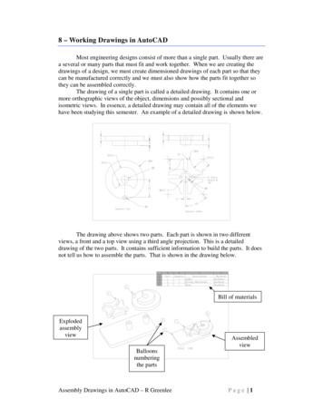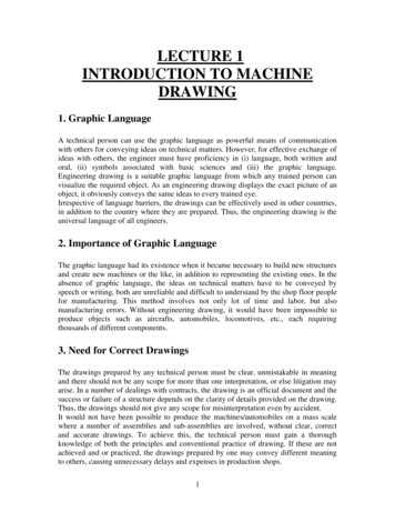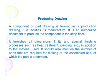
Transcription
Project DocumentationDocument SPEC-0002Revision HDocument and Drawing Control PlanRuth KnealeSystems Engineering GroupJuly 2012Reviewed By:Approved for release:R. HubbardSystems Engineer25-Sep-2012DateS. CraigSr. Systems Engineer25-Sep-2012DateAdvanced Technology Solar Telescope950 N. Cherry AvenuePhone 520-318-8102atst@nso.eduhttp://atst.nso.eduTucson, AZ 85719Fax 520-318-8500
Document and Drawing Control PlanREVISION SUMMARY:1. Date:Revision:Changes:29 October 2002AInitial release2. Date:Revision:Changes:30 July 2003BAddition of Physical System Interface descriptions and expansion of sections ofthe drawing appendix; tightening of assembly document requirements.3. Date:Revision:Changes:11 May 2004CRevised sections to match construction WBS/N2 chart changes. Includes changesto subsystem breakdowns, ICD numbering, and drawing numbering schemes.4. Date:Revision:Changes:1 October 2004DMajor revisions and additions to each section.5. Date:Revision:Changes:1 March 2005D.1Revisions to include more information on the Systems Database, ICD packages,and ICD naming conventions, and updates to the Drawing and Subsystem lists.6. Date:Revision:Changes:1 March 2006EInclude new information on bibliographic format information; Reference vs.Related Documents; and updates to almost all other sections.7. Date:Revision:Changes:13 April 2006E.1Added information about internal revision numbering and process for revisingreleased documents and drawings.8. Date:Revision:Changes:18 September 2006FUpdated all sections; now includes statement of purpose, expanded entries forreview & approval process, and clarifications for file naming and locations.9. Date:Revision:Changes:24 April 2009GUpdated all sections to reflect changeover from Enterprise PDMWorks toPDMWorks, general updating otherwise.10. Date:Revision:Changes:June 2012HMajor updates to all sections; added new CCB review and voting procedure;added section on contracts documentation management. Moved ePDM section tobefore revision section. Expanded document type definitions, and added a newdocument type.SPEC-0002 Rev HPage ii
Document and Drawing Control PlanTable of ContentsPREFACE . 11.STANDARDS . 21.1ELECTRONIC DOCUMENTATION LOCATIONS . 21.2PAPER DOCUMENTATION LOCATIONS . 21.3SYSTEMS DATABASE . 32.DOCUMENTS . 52.1NUMBERING. 52.2TYPES . 52.2.1Related and Reference Documents . 72.32.42.52.6CONTROLLED DOCUMENTS . 7TRACKING . 7COMPLETION AND DISTRIBUTION . 7FORMATTING . 82.6.1Bibliographic Formats . 82.72.83.3.13.23.33.43.54.4.1REVISING A RELEASED DOCUMENT. 8RELEASED DOCUMENTS ARCHIVE . 9DRAWINGS. 10NUMBERING AND LOCATIONS . 10REVIEWING AND RELEASING . 10DRAWING FORMATS . 10INTERFACE CONTROL DRAWINGS . 10REVISING A RELEASED DRAWING . 10INTERFACE CONTROL. 11INTERFACE CONTROL DOCUMENTS . 114.1.14.1.24.1.34.1.4Numbering .11Naming Convention .11Physical System Description .11Software Description .124.2INTERFACE CONTROL DRAWINGS . 124.3.1Naming Conventions .124.35.5.15.25.35.46.6.16.26.36.4INTERFACE DOCUMENT OR DRAWING APPROVAL . 12ENTERPRISE PDMWORKS . 13REVIEW AND RELEASE PROCEDURES . 14WORKFLOW . 14CHANGING STATE VIA TRANSITIONS . 16REQUESTING REVISIONS TO A FILE . 16CHANGE CONTROL. 17CHANGE CONTROL BOARD . 17APPROVED DOCUMENTS . 17CONTROLLED DOCUMENTS . 17CHANGE REQUESTS . 176.4.16.4.2How to Use a Change Request .17Extra Useful Information .186.5REQUESTS FOR W AIVER . 196.5.1How to Use an RFW: .19SPEC-0002 Rev HPage iii
Document and Drawing Control Plan6.6CCB ACTIONS ON CRS AND RFW S. 196.6.16.6.2CR Tracking and Status Reports .20RFW Tracking and Status Reports .207.ICD/N2 DIAGRAM. 21APPENDIX A: DOCUMENT TYPE LISTING . 22APPENDIX B: DRAWING NUMBER BREAKDOWNS . 23APPENDIX C: N2 SUBSYSTEMS . 24APPENDIX D: PROPRIETARY INFORMATION . 29APPENDIX E: CHANGE REQUEST FORM. 32APPENDIX F: REQUEST FOR WAIVER FORM . 33SPEC-0002 Rev HPage iv
Document and Drawing Control PlanPREFACE†The purpose of this Document and Drawing Control Plan is to identify and maintain documentation forATST, and ensure that this documentation remains consistent with the design requirements of the project.This is done by: Identifying types of and specific documentation;Storing identified documentation;Controlling, tracking and retrieving documentation;Review and approval of documentation, changes and revisions;Distribution.The following document is the primary management overview for configuration management (CM); thisdocument is a guideline for how to actually use the CM tools. †PMCS-0018, Revision Control and Configuration ManagementReferences:1. NASA Reference Publication 1370, “Training Manual for Elements of Interface Definition and Control”,January 19972. ES&H Volume IV, Part 41, Document 41.2, “Configuration Management Program Description”, UCRLAM-133867, November 20043. DSMC “Systems Engineering Management Guide”, January 1990SPEC-0002, Rev HPage 1 of 33
Document and Drawing Control Plan1.STANDARDSProject information will follow these established application standards: Word processing documents: either Microsoft Word or Rich Text Format.o For documentation such as reports, technical notes, etc., the document shall be formattedas defined in Section 2.6.Spreadsheets: Microsoft Excel.Presentations: Microsoft PowerPoint.Layouts and detailed engineering drawings:o All drawings will conform in general to ANSI Standards 14.24 “Types and Applicationsof Engineering Drawings”, 14.35M “Revision of Engineering Drawings and AssociatedDocuments”, and 14.100 “Engineering Drawing Practices”.o All 3d parts and assemblies will be created in SolidWorks.o All 2d drawings created from these 3d parts and assemblies, and schematics and pipingdiagrams, will be created and saved in Portable Document Format (PDF).o All drawings will use metric dimensioning where feasible.o All drawings will incorporate geometric dimensioning and tolerancing per ASMEY14.5M-1994, “Dimensioning and Tolerancing”.o All welding specifications shall be per ANSI/AWS Standard D1.1/D1.1M, “StructuralWelding Code – Steel”.o All drawings will have a border and title block per the ANSI Standards listed above.Optical drawings: Zemax.Software drawings: TBD.Electronics drawings: Altium Designer.Graphics: TIFF, PNG or JPEG format.Preliminary or draft work can use any application, but upon finalization and submission to SystemsEngineering, the work must be changed to one of the standard formats.1.1ELECTRONIC DOCUMENTATION LOCATIONSElectronic files will be managed by the SolidWorks PDMWorks Enterprise (ePDM) electronic documentmanagement system (aka the Vault; see Section 5). Staff will be trained on checking files into and out ofthe ePDM vault. File locations will match the Telescope Systems subset of the Work BreakdownStructure (WBS) structure (see Appendix C).The Business Manager will keep all business documentation digitally, in the Vault. The ContractsManager will keep all signed contracts, and other active contracts documentation will be kept digitally inthe Vault.1.2PAPER DOCUMENTATION LOCATIONSThe Systems Librarian will keep archival documentation such as review materials, archived proposals,reference sets, etc. in a series of filing cabinets. At this time, these archives do not include anything fromthe Director’s Office or the Project Scientist’s office, although this may change in the future.In addition, there is a Proprietary Information cabinet drawer in the archives. Any documentationremoved from this drawer, whether as an original or a copy, must follow the appropriate procedures as setforth in the Director’s “Protection of Proprietary Information” memo, dated February 12, 2003 (seeAppendix D). The Business Manager is the primary control person, and the Systems Librarian is thesecondary control person.SPEC-0002, Rev HPage 2 of 33
Document and Drawing Control Plan1.3SYSTEMS DATABASEThe Systems Librarian maintains a Systems Database in Access. This database is accessible by the stafffrom within the vault, and includes status reports for: Interface ControlDrawingsDocumentsBooksOther information tracked by Systems Engineering, such as staff publications, reference papers,etc.Status reports can be generated at any time by the staff by selecting the appropriate button. SystemsEngineering maintains a separate data-entry level within the database, for use only by the Systems Group.SPEC-0002, Rev HPage 3 of 33
Document and Drawing Control PlanSPEC-0002, Rev HPage 4 of 33
Document and Drawing Control Plan2.DOCUMENTSDocuments require a number for tracking, revision control, and database purposes. All ATST documentswill have a number assigned by Systems Engineering; to obtain a number, or for other documentationquestions, contact the Systems Librarian. Documents will be kept in the appropriate EPDM file vaultfolder, called “docs”, with subdirectories of “drd”, “sow”, “icd”, etc., as appropriate. When saving theelectronic copy of the file, the number is used as part of the filename, such as SPEC-XXXX Title.doc,into the appropriate ePDM vault directory.2.1NUMBERINGDocument numbering is very straightforward: ATST, followed by the document type, and finishing witha sequential numbering of the document within the document type. When a new document is started,staff should contact the Systems Librarian to get a document number; she will select from and enter it intothe Systems Database (see Section 1.4). Please DO NOT assign a number to a document yourself!Some document numbering examples are: 2.2ATST Technical Note #2 (Project Document TN-0002)ATST Report #12 (Project Document RPT-0012)ATST Specification #1 (Project Document SPEC-0001)DOCUMENT TYPESAt this time, the current document types in use at ATST are: Change Requests (CR). A CR is used whenever a proposed change affects the scope, budget,schedule or configuration of the observatory. See Section 6.4 for more. Compliance Matrices (CMX). Used to verify that all numbered requirements in a system’sConfiguration Specification are met. Contractor Reports (CON). These are deliverable outcomes from vendors. An example is CON-0093,“Ground Penetrating Radar Survey Summary Report of Findings.” Drawings (DWG). 2D drawings used for contractual and construction purposes. Note this documenttype does not include 3D CAD models. See Section 3 for more. Interface Control Documents (ICD). These detail the specific ways in which two systems interactwith each other, including mechanics, electronics, software, and safety interfaces. See Section 4 formore. Memorandums of Understanding (MOU). A document describing a bilateral or multilateralagreement between parties; a letter of intent. An example is MOU-0002, “PanSTARRS ElectricalReroute MOU.” Procedures (PROC). A written document or instruction detailing all relevant steps and activities of aprocess or procedure. An example is PROC-0012, “Enclosure Vent Gate Look Up Table CalibrationProcedure.”SPEC-0002, Rev HPage 5 of 33
Document and Drawing Control Plan Project Management Control System (PMCS). These documents provide information on planning,budgeting, and authorization for an integrated cost, schedule, and technical baseline for the Project.An example is PMCS-0014, “ARRA Risk Analysis Methodology and Rationale.” Reports (RPT). A detailed account or statement of an event or situation, as a result of observation orinquiry. Used for scientific purposes. An example is RPT-0045, “Inference of telescope polarization:Dunn Solar Telescope using Facility Infrared Spectropolarimeter Observations." Requests for Waiver (RFW). An RFW is used to obtain authorization to deviate from a specification;it is submitted by the Contractor via the COTR. See Section 6.5 for more. Reviews (REV). This document type is for both the collected material provided at a design review,and for the review reports themselves. For example, REV-0085 is for the material provided toreviewers at the 2012 Safety Review; REV-0086 is the “2012 Safety Review Committee Report.”Design review documentation should include the information defined in PMCS-0022, Design ReviewGuidelines. Specifications (SPEC). For ATST, there are two categories of SPEC documents: configuration, andnon-configuration.Non-configuration Specifications comprise information essential to the construction and managementof the Observatory and its assemblies, but are not detailed engineering requirements. Some examplesof this type are: This document, SPEC-0002, “Document and Drawing Control Plan”; SPEC-0050, “Procurement Management Plan”; SPEC-0130, “ATST Relocation Policy”; A Preliminary Design Definition Document, which details the assembly’s optical,mechanical, electrical and software configurations. It provides insight on the designmethodology and rationale supporting the chosen configuration as well as safety issuesassociated with the chosen configuration. An example is SPEC-0093, “PA&C PDD.” A Critical Design Definition Document, which details the assembly’s optical,mechanical, electrical and software configurations. It provides insight on the designmethodology and rationale supporting the chosen configuration as well as safety issuesassociated with the chosen configuration. An example is SPEC-0107, “VBI CDD.”Configuration Specifications (or requirements) are a translation of high-level requirements placed onan assembly into specific, detailed engineering requirements. These specifications are descriptions orassessments of requirements, dimensions, materials, etc., that define how the assembly is to be built.Some examples of configuration Specification documents, which use words like “shall” and “will”,are: An Operational Concept Design Definition, which includes information on thephilosophy and concept that underpins a subsystem. An example is SPEC-0106, “VBIOperational Concepts Definition.” A Design Requirements Document, which specifies the 'build to', 'code to', and 'buy to'requirements for products. It includes the Functional Requirements (which are necessarytasks, actions, or activities that must be accomplished by a system) and PerformanceRequirements (which quantitatively state the extent to which a system function must beexecuted). For example, SPEC-0010, “Enclosure Specification Document.”SPEC-0002, Rev HPage 6 of 33
Document and Drawing Control Plan Technical Notes (TN). A technical note provides supplementary information on a subsystem,assembly or application, or describes a problem or feature beyond the scope of other documentation.Written by engineers for engineers, they are usually in the form of short, focused documents thatsupply technical details that inform, but do not contain any requirements. They use words like“should” and “can”. An example is TN-0097, “The GOS Optical Environment.”oTNs include Reference Design Studies and Analyses, a document or document set that includesone plausible design option, developed in enough detail to allow cost and performance analysis.The analyses and studies are supporting documents prepared in house or externally. An exampleis TN-0102, “Instrument Control System RDSA.”Other document types will be specified as needed.2.2.1Related and Reference DocumentsRelated documents are Project documents called by other Project documents. For example, an ICD maycall a Specification as a related document; copies of this document would be provided to ICD recipients,as would revisions to that related document. Or, a Specification could call a Technical note as a relateddocument. There are also Related Drawings in ICDs that are treated the same way.Related documents are required by the main document.Referenced documents are documents (i.e. journal papers, conference proceedings) that are called by adocument but are not a required reference in that document. Bibliographic information is provided, butnot a copy of the referenced document.Referenced documents are for further information, but are not required by the main document.2.3CONTROLLED DOCUMENTSIt's important to understand there are two kinds of controlled documents that exist in the vault system:Revision Controlled - documents that do not affect the configuration of the observatory (i.e. do not affectthe budget, schedule, scope, or performance). These are typically items like reports and technical notes, orcontract items like SOWs; they are controlled in as much as responsible engineers or scientists should beaware when they are changed, but they do not need to go through the Change Control Board (CCB) forapproval of changes.Configuration Controlled - documents that do affect the configuration of the observatory. Anything thatimpacts budget, schedule, scope, or performance is a configuration controlled document, and any changesto it must be requested via a Change Request (CR) and CCB. Configuration Items (CIs) include items notnecessarily in a typical document, such as a schedule milestone change, a budget change (either a transferbetween WBS elements or a request on contingency), a change to scope, etc.2.4TRACKINGWhile working on a document – any kind of document – the file should be kept in the ePDM vault; itprovides for version control of a document even without it being a released document, and it provides acentral and backed-up repository for working files. A file’s history can be reviewed on-demand, andearlier versions can be restored if needed. The status of documents is summarized in the SystemsDatabase (see Section 1.3).2.5COMPLETION AND DISTRIBUTIONSPEC-0002, Rev HPage 7 of 33
Document and Drawing Control PlanWhen a document is completed, it should be submitted for review using the ePDM system (see Section6). After review and approval by the appropriate lead engineer and the appropriate group manager, thedocument will be sent to Systems Engineering for review. The Systems Engineer will determine if thedocument is controlled or not, and whether it is private or public. An example of a controlled publicdocument would be an ICD; an approved public document would be a report; an approved privatedocument a vendor’s report; and a controlled private document a contract.Upon final approval of a document, the Systems Librarian will be notified by ePDM and will carrythrough the appropriate processing. This may include updating headers, footers and revision letters,adding signature dates, etc. At this point, a PDF copy of the current revision of the file is also stored inthe Released Documents Archive.2.6FORMATTINGProject documentation will use an established cover sheet and follow a modified SPIE manuscript format(a template of which is available on the internal web site in Word format, and in the Templates directoryof the vault): 1” margins on all sides, with 0.5” headers and footers.Headers will include the title of the document, flush right, in Arial 10pt italic.Footers will include version or revision number, flush left, and page numbers, flush right, both inArial 10pt italic.Normal or body text: Times New Roman, 11pt1st Header: Arial, 12pt, bold, flush left, Level 1 numbering (i.e. 2.)2nd Header: Arial, 11pt, bold, small caps, flush left, Level 2 numbering (i.e. 2.1)3rd Header: Arial, 11pt, bold, flush left, Level 3 numbering (i.e. 2.1.1)4th Header: Arial, 10pt, bold, flush left, Level 4 numbering (i.e. 2.1.1.1)If there are any questions, contact the Systems Librarian.2.6.1Bibliographic FormatsFor a description of Reference and Related Documents, please see Section 2.2.1.Reference (i.e. Non-Project) documents: these follow SPIE manuscript format. Paper: Author(s), “Title”, Journal, Volume, Inclusive pages, Year of publication.Proceedings or book: Author(s), “Paper or chapter title”, Volume Title, Editor(s), Volume, InclusivePages, Publisher, City of publication, Year of publication.Related (i.e. Project) documents: these follow a modified SPIE manuscript format. Author(s), “Title”, ATST Project Document Document Number .Should a Project Document be used as a Reference Document, use the above format but add theappropriate inclusive page numbers before the year of publication.2.7REVISING A RELEASED DOCUMENTFor internal revisions to a document (such as may occur when two people are revising the file andshipping it back and forth), use the current revision letter and a version number. For example, if a file isat the official released revision of B but is on the third iteration of an update, it would be labeled “B3” inSPEC-0002, Rev HPage 8 of 33
Document and Drawing Control Planthe Version History of the file. (You can see a working example of this in this document’s VersionHistory.)A file does not go up to the next revision letter until after it has been appropriately reviewed andapproved. See Section 6 for details on change control processes.2.8RELEASED DOCUMENTS ARCHIVEThe Systems Librarian keeps a PDF copy of all versions of all released documents, drawings, and ICDs inan archive folder in the vault (Vault\Library\Archives). The most recent version of documents will be inthe higher level folders, and earlier versions will be in subfolders called “Previous Versions”.SPEC-0002, Rev HPage 9 of 33
Document and Drawing Control Plan3.DRAWINGSDrawing numbers (for all types of drawings) follow a number structure based on the Telescope Systemssubset of the Work Breakdown Structure (WBS), as outlined in Appendix C. Previous to this structuredefinition in July 2002, some site survey drawings used a different structure; that is also noted at the endof Appendix B.NOTE that in ATST’s context, “drawings” means any 2D drawings used for contractual and constructionpurposes, not 3D SolidWorks files.3.1NUMBERING AND LOCATIONSThe construction of the drawing number is a straightforward, sequential 5-digit number, in the formATST-DWG-XXXX. When a new drawing is needed, staff should contact the Systems Librarian to get anumber; she will select from and enter it into the Systems Database. Please DO NOT assign a numberto a drawing yourself!The revision letter will not be a part of the drawing number but will be in the title block of the drawing,and in the filename. ePDM will manage internal version information. When saving the electronic copy ofthe file, the drawing number is used as part of the filename, such as ATST-DWG-XXXX TitleRevX.pdf‡, into the appropriate ePDM vault directory. Drawing status reports in a variety of ways areavailable from the Systems Database, such as all drawings, drawings by subassembly, etc.3.2REVIEWING AND RELEASINGWhen a drawing is completed, the author should submit the document for review using the ePDM system(see Section 5). The appropriate lead engineer and group manager will be notified, and will review andapprove the drawing. Upon final approval, the Systems Librarian will store a PDF copy of the currentrevision of the drawing in the Released Drawings Archive.Drawings must be reviewed and approved before being sent out with a contract or work order.3.3DRAWING FORMATSA drawing format based on the ANSI Y14.1M standard will be used on every drawing. Both 2d drawingand 3d SolidWorks templates for each size of drawings B through E are available from within the ePDMvault, in \SysDocs\SW Library\Solidworks Templates.3.4INTERFACE CONTROL DRAWINGSSee Section 4.2.3.5REVISING A RELEASED DRAWINGSee Section 6 for the process to request revisions on a released drawing.Since drawing files are kept in PDF format, a slight change to the process is required; rather than editingthe PDF file, a new PDF file is generated from the appropriate SolidWorks drawing file.‡A note regarding file type: 2D drawings are generated via the 3D models; in order to maintain consistency indrawings (especially interface drawings) so they do not change as the models change, the 2D drawing file will besaved in PDF format.SPEC-0002, Rev HPage 10 of 33
Document and Drawing Control Plan4.INTERFACE CONTROL4.1INTERFACE CONTROL DOCUMENTSAn interface control document (ICD) defines the physical and software interactions between twoassemblies (or subsystems), along with any other relevant information. An ICD does not duplicate aspecification, but should clearly identify and control interfaces between designs and enable compatibilityto be demonstrated; at a minimum, it should define and illustrate physical and functional interfacecharacteristics.The main areas to be addressed within the document are:1. Subsystem Descriptions2. Related Documents and Drawings3. Physical System Description Mechanical Optical Electrical Mass/Balance Thermal4. Software Description5. Safety IssuesThe identified nodes for ICDs are shown on the N2 diagram (see Section 7). Current subsystems arelisted in Appendix C.4.1.1NumberingICDs will always follow a “lowest first” numbering scheme; for example, an interface between theTelescope Control System (4.4) and the Telescope Mount Assembly (1.1) will have an ICD number of1.1/4.4. This scheme will be used throughout interface control.4.1.2Naming ConventionICD documents should follow the naming convention of “A.B-X.Y Title.doc”, where A.B is the firstsubsystem assembly and X.Y is the second. Using the above example, the file would be called “1.1-4.4TMA to TCS.doc”. ICD files will be “shared” between the two assemblies in the ePDM vault.4.1.3Physical System Description*The mechanical section is used to define and control the mechanical features, characteristics, dimensions,and tolerances of any equipment design that affect the des
Documents”, and 14.100 “Engineering Drawing Practices”. o All 3d parts and assemblies will be created in SolidWorks. o All 2d drawings created from these 3d parts and assemblies, and schematics and piping diagrams, will be created and saved in Portable Document Format (PDF). o

