Transcription
Name--------------------------Roll No.------------------------LABORATORY MANUALTA201A MANUFACTURING PROCESSES-IDEPARTMENT OFMATERIALS SCIENCE AND ENGINEERINGIndian Institute of Technology, KanpurCOURSE INSTRUCTORLAB IN-CHARGECOURSE IN-CHARGEProf. Kantesh BalaniMr. Anil K. VermaMr. I. P. SinghPh: 6194Email: kbalani@iitk.ac.inLectureLaboratoryPh: 7978Email: akumarv@iitk.ac.inPh: 7978Email: indraps@iitk.ac.inTuesdays ; 09:00 am – 09:50 am ; Venue L-20Monday to Friday(As per one of the assigned days of your section)02:00 pm to 05:00 pmVenue: Engineering Metallurgy Lab.2018-2019 SEM-II1
CONTENTSS .20.21.DescriptionFront PageContent PageLaboratory ScheduleTutor and TAsGrading Policy, Safety Rules and Recommended ReadingLaboratory Turn Distribution & Task During ExerciseMarks Distribution and Project Framing ScheduleOutline of Project Report and Point To Be Used In The ProjectLimitation of ProjectAbout ProjectMaterials List for ProjectIntroduction To Casting ProcessesExercise 1 - AIntroduction To Sheet Metal formingExercise 2 - BIntroduction To Welding ProcessesExercise 3 - CIntroduction To Brazing ProcessesExercise 4 - DIntroduction To Demonstration with few ExercisesExercise 5 - E2Page No.010203040506070808091011141618202223252731
TA201A: Manufacturing Processes - IEngineering Metallurgy Lab2018-2019, Sem II, Laboratory Schedule1stLab 12ndLab 23rdLab 34thLab 45thLab rns7thPro 18thPro 29thPro 310thPro 411thPro 512thPro 611/225/29/311/325/31/48/413/4/19 (Sat)5/212/226/25/312/326/32/49/413/4/19 (Sat)30/16/213/227/26/313/327/33/410/413/4/19 (Sat.)24/131/17/214/228/27/314/328/34/411/413/4/19 (Sat)25/11/28/215/21/38/315/329/35/412/413/4/19 (Sat)Day & SectionFirst Lab:8th January 2019Mid Semester ExaminationMid Semester RecessLast LabProject EvaluationEnd Semester Examination:::::18 February to 23 February 201916 March to 24 March 201912 April 2019Apr. 13, 2019 (Saturday)21 April to 30 April 2019Mr. I P SinghCourse In-Charge7978/indraps@Mr. AK VermaLab In-Charge7978/akumarv@6thLabExam Drawing13thProjectEvaluation@*Make-up lab on Saturday12/01/2019@10:00 am to 1:00 pm (Monday Batch)09/03/2019@10:00 am to 1:00 pm (Monday Batch)Prof. Dipak MazumdarFaculty In-Charge7328/dipak@3Prof. K BalaniCourse Instructor6194/kbalani@
Tutor & TAs orE-mailMobile No.crupesh@iitk.ac.inMr. Rupesh Chafleashishg@iitk.ac.inProf. Ashish Gargkbalani@iitk.ac.inProf. Kantesh Balanisomar@iitk.ac.inProf. Shobit OmarProf. Anandh Subramaniam anandh@iitk.ac.in81728 56986941515337591982 2879894540 1709399196 WednesdayThursdaySectionsD1, D2, D6(CHE, MSE)NameEmailluttam@iitk.ac.in89789 44743Mr. Biswajit Janabiswajit@iitk.ac.in84297 33489anshulpl@iitk.ac.indhamodar@iitk.ac.in63874 4315288978 99126ritobrat@iitk.ac.in94330 44720seshan@iitk.ac.in78872 94904rmitra@iitk.ac.in70769 85611riyazm@iitk.ac.in93812 65818debayanc@iitk.ac.in97485 63965ratn@iitk.ac.in62052 54926D3, D4, D5 Mr. Anshul Patel(AE, CHE, MSE) Mr. T Dhamodar NaiduD7, D8, D9 Mr. Ritobrata Saha(MSE,CE)Mr. Eshan SaraswatD10, D11, D12 Mr. Rahul Mitra(CE, PHY)Mr. Md RiyazMr. Debayan ChatterjeeFridayPhoneMr. L Uttam ReddyD13, D14, D15(CE, CHM, ECO) Mr. Rahul Ratn*Assigned with course instructor*Mr. Debasis Rathdebrath@iitk.ac.in472057 31775
General InformationGRADING POLICY:Theory (Total 50%): Mid Semester Exam (2 hours) 20%, End Semester Exam (3 hours) 30%Laboratory (Total 50%): Weekly lab quiz 5%, Attendance 5%, Weekly Job: 5%, Lab Exam 5%,Project Report 10%, Project 20%Minimum 40% required for passing the courseThere will be total 13 lectures starting from 8th January 2019.100% attendance in lectures is expected.Attending all the lab turns is mandatory for passing the course. No make-up lab will beprovided for cultural/ sports activities or for casual leaves.SAFETY:Wearing covered shoes (preferable hard-toed) is mandatory. Do not wear loose clothing.To avoid injury, the student must take the permission of the laboratory staff before handlingany machine. Careless handling of machines may result in serious injury.Students must ensure that their work areas are clean and dry to avoid slipping.A leather apron, safety goggles and leather hand gloves will be issued to each student duringWelding and Brazing Exercise. Students MUST wear the apron, safety goggles and hand gloves.At the end of each experiment, students must clear off all tools and materials from the work area.During Sheet Metal forming wearing cotton hand gloves is compulsory.RULES:Follow the lab timing with proper attire. There will be two attendances: Initial attendance (at sharp 2 PM)to be taken by TAs at the beginning of lab session and final one consists of filling the Job submission form.Do not use cell phone inside the lab during lab timing.Students arriving late would be sent back.Students must come to the laboratory wearing (i) Trousers, (ii) Full-sleeve tops and (iii) Leather shoes(Closed shoes). Half pants, loosely hanging garments, slippers and sandals are not allowed.Before commencement of experiment there will be Lab-Quiz of given questions in the starting of lab basedon video uploaded on course website.Every student should obtain a copy of Manufacturing Processes Laboratory Manual. You are requested tobring your lab manual every day. You can purchase lab manual from lab on the first turn.RECOMMENDED READING:Fundamental of Modern Manufacturing: Materials, Processes and Systems, Mikell P. GrooverFundamental of Manufacturing, G. K. Lal & S. K. ChoudhuryMaterials & Processes in Manufacturing, E. P. DeGarmo, J. T. Black and KohserManufacturing Engineering & Technology, S. KalpakjianE. P. Degarmo: Materials & Processes in Manufacturing, Macmillan.The Science and Engineering of Materials, Askeland, Fuley, Wright and Balani5
Laboratory Turn Distribution & Tasks During ExerciseDemonstration & Practice Sessions (1-5 turns) Molding and CastingSheet Metal FormingWelding ProcessBrazingDemo with few exercises.(Mr. I P Singh, Mr. Anurag Prasad, Mr. Shilankar)(Mr. Rakesh Kumar)(Mr. Anil Kumar Verma & Mr. Mewa Lal)(Mr. Gaurav Mishra)(Mr. Nripen Deka) Lab Examination & Final Drawing Submission (6 turns). (All Staff) Project (7- 12 turns). (All Staff) Project Evaluation - (13 turns) (All Tutors and Staff)Rotation of practice turns6
Marks Distribution & ResponsibilitiesFor Theory:Mid Semester20 Tutors InstructorEnd Semester30 Tutors InstructorTotal50For Lab:Lab Quiz Attendance in Lab5 5 TAsExperiments/job during lab5 Lab In-chargeLab ExamProject Job(Innovation, Finish and volume of work)Project Report and Engineering Drawing(Neatness, sequence, timely submission)Total5 Lab In-charge &Tutors TAs20 Tutors Lab In-charge CourseInstructor10 Tutors Lab In-charge CourseInstructor50Project Framing Schedule2nd Turn:Project group formation3rd Turn:Bring minimum of 3 project ideas along withRough sketch. One project idea will beFinalized in this turn.4th Turn:Discussion on finalized project with properdrawing as per engineering norms, includingparts drawing (with numbering and materials )5th Turn:Final discussion with drawing and process(Bring complete report)6th Turn:Final drawing submission.7
OUTLINE OF PROJECT REPORT: Project Title:Course Instructor:Tutor:Staff Lab In-charge:Staff Course In-charge:Roll Number, Name and Signatures (of all students in the als List (that has been used):Member Work Distribution/ Contribution:Motivation:Isometric Drawing:Part Drawing:POINTS TO BE USED IN THE PROJECT: Which part will be made from which process? You would learn basic of manufacturing techniques in this lab like metal forming,casting and welding and brazing. Out these, you must involve any of three techniquesin your project. Proper drawing should be done. Part drawing should be made with respect to dimensions. You have to make isometric and part drawing with appropriate dimensions on A4sheet.Limitation of Project:o Size of the project: 40 cm 40 cm 40 cm (strictly to be followed) and Total weightfor casting objects should not exceed 1.5 kg. Aluminum and cast iron per project asper required. Oversize/overweight project will affect your final evaluation.o Student must follow the Total Project Weight should not exceed 5 kg.o External color/paint cannot be used.o Don’t polish/grind cast component used in your project.8
ABOUT PROJECT1. Plan your project carefully. Do not make it unnecessarily complicated. The project has to beentirely your work. Laboratory staff (Technical guide) will provide you only the guidelines. Theywill not make any part of your project.2. Your tutor, lab in-charge and the technical staff will advise you on the design of your project.3.There will be no extra lab turn for project.4. The project groups will be formed and informed to you by the end of the second lab turn.5. You should come with at least three ideas with the rough sketch on the third lab turn for thediscussion and to be frozen one idea.6. On the fourth and fifth lab turns you should come with all necessary information such as drawing;manufacturing process for each part etc. The drawing should be as per the engineering norms.7. The copy of final project drawing with material list and process plan (complete report) must besubmitted on the sixth lab turn. You should select materials from the list only. (The list will bedisplayed on lab notice board).8. The exact responsibilities of each group member should be specified.9. Two best projects will be chosen from each day. There will be one overall best project award outof all the shortlisted projects. The certificates will be given to the students (winners) in a commongathering after project evolution.10. Size of the project: 40 cm x 40cm x 40cm (to be followed strictly) and total weight for casting objects(cast iron should not exceed 1.5 kg OR aluminium part should not exceed 1 kg per project as perrequired. Oversized and over weighted project will be credited negative marking.11. During project, do not grind the cast part without the permission of foundry lab staffs.12. Aluminum parts do not grind.13. At least three operations are to be incorporated in the project (Welding, Brazing, Casting, Sheet metal)14. Moving parts in your project will be given extra credit during evaluation.15. External colour/paint cannot be used. Polishing/grinding of cast component used will not allow.In case of any doubt regarding the above, please contact Mr. I.P. Singh (indraps@/7978).9
Materials List for Project WorkTA-201,Manufacturing ProcessesSr. 293031323334ItemsMild Steel FlatMild Steel FlatMild Steel Round RodMild Steel Round RodMild Steel Round RodMild Steel Round RodMild Steel Round RodMild Steel Round RodMild Steel Round RodMild Steel Round RodMild Steel Square RodMild Steel Square RodMild Steel Round PipeMild Steel Round PipeMild Steel Round PipeMild Steel Square PipeMild Steel Square PipeMild Steel AngleGalvanized Iron SheetGalvanized Iron SheetMild Steel SheetMild Steel SheetMild Steel SheetMild Steel FevicolSand Paper for thermocolSmall Nut-Bolt with Mild steel WasherThin Galvanized WireAluminium & Cast iron10Size25 3 mm225 5 mm225 mm dia10 mm dia8 mm dia6 mm dia5 mm dia4 mm dia3 mm dia2 mm dia10 10 mm26 6 mm225 mm dia (1" dia)18 mm dia (3/4" dia)10 mm dia25 25 mm215 15 mm225 25 mm20.35 mm0.5 mm0.5 mm0.7 mm1.0 mm2.0 mm1/2 inch1 inch1.5 inch2 inch3 inchsmall size tubeNumber 80-------1 mm and 2 mm diaFor casting
INTRODUCTION TO CASTING PROCESSESBackgroundCasting is one of oldest and one of the most popular processes of converting materials into final usefulshapes. Casting process is primarily used for shaping metallic materials; although it can be adopted forshaping other materials such as ceramic, polymeric and glassy materials. In casting, a solid is melted,treated to proper temperature and then poured into a cavity called mold, which contains it in propershape during solidification. Simple or complex shapes can be made from any metal that can be melted.The resulting product can have virtually any configuration the designer desires.Casting product range in size from a fraction of centimetre and fraction of kilogram to over 10 metersand many tons. Moreover, casting has marked advantages in production of complex shapes, of partshaving hollow sections or internal cavities, of parts that contain irregular curved surfaces and of partsmade from metals which are difficult to machine.Several casting processes have been developed to suit economic production of cast products withdesired mechanical properties, dimensional accuracy, surface finish etc. The various processes differprimarily in mold material (whether sand, metal or other material) and pouring method (gravity,pressure or vacuum). All the processes share the requirement that the material solidify in a manner thatwould avoid potential defects such as shrinkage voids, gas porosity and trapped inclusions. Any castingprocess involves three basic steps, i.e. mold making, melting and pouring of metals into the moldcavity, and removal and finishing of casting after complete solidification. One of the majorclassification of casting is done based on whether the mold is used again or it is prepared fresh everytime. Sand casting is an example of expendable mold process or where the mold is broken after everycasting to remove the component. In this lab, students will go practice this particular process by makingthe mold and then pouring the liquid metal into the mold to form a final component.SAND CASTING PROCESSESSand is one of the cheaper, fairly refractory materials and hence commonly used for making moldcavities. Sand basically, contains grains of silica (SiO2) and some impurities. For mold makingpurposes sand is mixed with a binder material such as clay, molasses, oil, resin etc.Green Sand MoldingIn green sand molding process, clay (a silicate material) along with water (to activate clay) is used asbinder. The mold making essentially consists of preparing a cavity having the same shape as the part tobe cast. There are many ways to obtain such a cavity or mold, and in this demonstration you will learnto make it using a wooden ‘pattern’, metal ‘flasks’ and ‘green-sand’ as mold material.A pattern is a reusable form having approximately the same shape and size as the part to be cast. Apattern can be made out of wood, metal or plastic; wood being the most common material. Green sandrefers to an intimate mixture of sand (usually river sand), bentonite clay (3-7 percent by weight of sand,11
to provide bonding or adhesion between sand grains), and water (3-6 percent by weight of sand,necessary to activate the bonding action of the clay). Mixing the above ingredients in a sand4 mullerbest provides the intimate mixing action. In practice, a major part of this sand mixture consists of‘return sand’, i.e. the reusable portion of the sand left after the solidified metal casting has beenremoved from the mold. Molding flasks are rectangular frames with open ends, which serve ascontainers in which the mold is prepared. Normally a pair of flasks is used; the upper flask is referredto as ‘cope’ and the lower one as ‘drag’. A riddle is a relatively coarse sieve. Riddling the green sandhelps in breaking the lump and aerates the sand.Sometimes the casting itself must have a hole or cavity in or on it. In that case the liquid metal must beprevented from filling certain portions of the mold. A ‘core’ is used to block-off portions of the mold frombeing filled by the liquid metal. A core is normally made using sand with a suitable binder like molasses.Core is prepared by filling the core-box with core sand to get the desired shape and the baking this sand corein an oven at suitable temperature. During mold making a suitable ‘gating system’ and a riser’ is alsoprovided. The gating system is the network of channels used to deliver the molten metal from outside themold into the mold cavity. The various components of the gating system are pouring cup, sprue, runners andgates. Riser or feeder head is a small cavity attached to the casting cavity and the liquid metal of the riserserves to compensate the shrinkage in the casting during solidification. Fig. 1 below shows the various partsof a typical sand mold. Several hand tools, such as rammer, trowel, sprue pin, draw spike, slick, vent wire,gate cutter, strike off bar etc. are used as aids in making a mold.Melting and Pouring of MetalsThe next important step in the making of casting is the melting of metal. A melting process must becapable of providing molten metal not only at the proper temperature but also in the desired quantity,with an acceptable quality, and within a reasonable cost. In order to transfer the metal from the furnaceinto the molds, some type of pouring device, or ladle, must be used. The primary considerations are tomaintain the metal at the proper temperature for pouring and to ensure that only quality metal will getinto the molds. The operations involved in melting of metal in oil fired furnace/induction furnace andpouring of liquid metal into the mold cavity will be shown during the demonstration.Removal and Finishing of CastingsAfter complete solidification, the castings are removed from the mold. Most castings require somecleaning and finishing operations, such as removal of cores, removal of gates and risers, removal offins and flash, cleaning of surfaces, etc.12
Fig. 1: Cross section of a typical two-part sand mold, indicating various mold components andterminology.Fig. 2: Schematic illustration of the sequence of operations for sand casting.13
EXERCISE-1MOLD MAKING & CASTINGObjective1. To prepare a pattern for given object for lost form casting.2. To prepare a Green sand mold from the prepared pattern.3. To melt and pour Aluminum metal into the mold.Equipment and MaterialsPattern, core box, molding flasks, molding tools, sand muller, riddle, sand, bentonite, core baking oven,thermocole, melting furnace, fluxes, pouring ladle, pyrometer, hacksaw, file.ProcedurePattern for lost form castingFig. 3: Foam pattern and the corresponding cast object.Mold Making(i)(ii)(iii)(iv)(v)Place the drag part of the molding flask and riddle molding green sand to a depth of 2 cm inthe drag.Place the pattern at the centre of the drag (flask)Pack the sand carefully around the pattern as shown in figure 4. Heap more molding sand inthe drag and ram with rammer carefullyPlace the core half of the pattern over the drag pattern matching the guide pins and also placethe gating system with sprue and riser in proper positions.Complete the cope half by repeating steps 3. Remove the extra sprue and riser pins and makea pouring basin.14
Fig. 4: Equipment for sand mixing and a prepared mold.Melting and Pouring(i)(ii)(iii)(iv)(v)Melt the metal in the furnace. Use appropriate fluxes at proper stages and measure metaltemperature from time to time.Pour the molten metal into the pouring ladle at a higher temperature (say 100oC higher) thanthe pouring temperature. As soon as the desired pouring temperature is reached, pour theliquid metal into the mold in a steady stream with ladle close to the pouring basin of themold. Do not allow any dross or slag to go in.Allow sufficient time for the metal to solidify in the mold. Break the mold carefully andremove the casting.Cut-off the riser and gating system from the casting and clean it for any sand etc.Inspect the casting visually and record any surface and dimensional defects observe.Fig. 5: Furnace for melting metal for pouring into mold.15
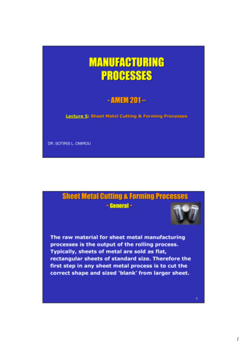
INTRODUCATION TO METAL FORMINGSHEET METAL FORMINGMany products are manufactured from sheet metal involving combination of processes such as shearing,bending, deep drawing, spinning etc. These processes are characterized by localized deformation andconfiguration changes and are together called “Sheet Metal Forming”. These processes do not result inbulk shape change of the parts, but lead to configurational changes. Sheets have high surface area tovolume ratio of starting metal which distinguishes these from bulk deformation. Sheet metal forming isoften called ‘press working’ as presses are required to perform these operations. Parts are usually calledstampings and usual tools involve punches and dies. Sheet metal operations can involve combination ofstresses, eg. Stretching of the metal (tensile stresses) Bending of the metal (tensile and compressive stresses) Cutting of the metal (shear stresses)Fig. 6: Schematic of some sheet metal working operations (top) shearing (bottom) bending.16
(a)(b)(c)Fig. 7: Some of the apparatus available in engineering metallurgy lab to perform sheet metal forming(a) Shearing equipment (b) Bending equipment (c) Folding equipment.17
EXERCISE-2SHEET METAL FORMINGObjective(i) To prepare a sheet metal product (Funnel).(ii) Report the various parameters for the various passes during the rolling of the given metal piece.Equipment & materialMallet, Hand Snip, Bench Vice, Grooving Tool, Scriber, Scale, Marker, Light Weight Hammer, Dividerand Metal SheetDemonstrationSelf secured sheet metal joints(a) Internal grooved jointMark out portions of given sheets near edges to be joined with a marker.Fold the sheets at edges in the portion marked, first at right angles to the plane of the sheetand then at 180० to the plane.Insert one folded sheet into the other.Groove the seam using grooving die.(b) Double grooved jointFold sheets after making them as per the instructions given.Cut a piece of sheet (called strap) of required width.Strap width (4x size of marked edges) (4 x thickness of sheet).Close the edges of the strap slightly.Slip the strap on the bent edges of the sheets after bringing them.(c) Knocked-up jointFold one sheet and close edges slightly.Bend one sheet to form a right angles band.Slip the second sheet in the folded one.Close the right angled sheet using a mallet.18
Fig. 8: Approximate dimensions of the funnel to be fabricated.Procedure for funnel:Draw the elevation on full scaleComplete the cone by extending the lines A and GChoose a point Z and draw curves with Z as a center, and ZA and ZX as radiusDraw the vertical line Z3, meeting the internal curve at D, and external curve at 3Starting from D mark lengths DC, CB, BA, DE, EF and FG, each equal to nd/6.Again starting from 3 mark length 3-2, 2-1, 1-0, 3-4, 4-5 and 5-6, each equal to πd/6. (D and dare major and minor diameters)Draw another curve with Z as a center and ZX 5 mm as radius.Joint AO and G6 and extend it to cut the outer curve at points H and I, respectively.Provide a margin of 5 mm on one side, and 10 mm on another side for joint.Cut out the required portion and form the conical portion.Make the bottom half of the funnel.Fig. 9: Final form of funnel to be fabricated in the lab.19
INTRODUCTION TO JOINING PROCESSESObjectiveTo study and observe the welding and brazing techniques through demonstration and practice (ARC,MAG, Brazing)BackgroundSolid materials need to be joined together in order that they may be fabricated into useful shapes forvarious applications such as industrial, commercial, domestic, art ware and other uses. Depending onthe material and the application, different joining processes are adopted such as, mechanical (bolts,rivets etc.), chemical (adhesive) or thermal (welding, brazing or soldering). Thermal processes areextensively used for joining of most common engineering materials, namely, metals. This exercise isdesigned to demonstrate specifically: gas welding, arc welding, resistance welding, brazing.WELDING PROCESSESWelding is a process in which two materials, usually metals, and is permanently joined together bycoalescence, resulting from temperature, pressure, and metallurgical conditions. The particularcombination of temperature and pressure can range from high temperature with no pressure to highpressure with any increase in temperature. Thus, welding can be achieved under a wide variety ofconditions and numerous welding processes have been developed and are routinely used inmanufacturing.Fig. 10: Schematic of a welding processTo obtain coalescence between two metals following requirements need to be met: (1) perfectly smooth, flator matching surfaces, (2) clean surfaces, free from oxides, absorbed gases, grease and other contaminants,(3e) metals with no internal impurities. These are difficult conditions to obtain. Surface roughness isovercome by pressure or by melting two surfaces so that fusion occurs. Contaminants are removed bymechanical or chemical cleaning prior to welding or by causing sufficient metal flow along the interface sothat they are removed away from the weld zone friction welding is a solid state welding technique. In manyprocesses the contaminants are removed by fluxing agents.20
The production of quality welds requires (1) a satisfactory heat and/or pressure source, (2) a means ofprotecting or cleaning the metal, and (3) caution to avoid, or compensate for, harmful metallurgicaleffects.Arc WeldingIn this process a joint is established by fusing the material near the region of joint by means of anelectric arc struck between the material to be joined and an electrode. A high current low voltageelectric power supply generates an arc of intense heat reaching a maximum temperature ofapproximately 5500 C. The electrode held externally may act as a filler rod (consumable electrode) orit is fed independently of the electrode (nonconsumable electrode). Due to higher levels of heat input,joints in thicker materials can be obtained by the arc welding process. It is extensively used in a varietyof structural applications.OThere are so many types of the basic arc welding process such as shielded metal arc welding (SMAW), gasmetal arc welding (GMAW), gas tungsten arc welding (GTAW), submerged arc weldingFig. 11: Schematic of a shielded metal arc welding process.21
EXERCISE-3ARC WELDINGObjectiveTo prepare a butt joint with mild steel strip using MAG & MMAW technique.Equipment and materialsWelding unit, consumable mild steel wire, mild steel flats (100 x 25 x 5 mm), protecting gas, WireBrush, Tongs etc.ProcedureClean the mild steel flats to be joined by wire brush.Arrange the flat pieces properly providing the gap for full penetration for butt joint(gap ½thicknesses of flats).Practice striking of arc, speed and arc length controlSet the welding current, voltage according to the type of metal to be joined.Strike the arc and make tacks at the both ends to hold the metal pieces together duringthewelding processLay beads along the joint maintaining proper speed and arc length (Speed 100-150 mm/min).Clean the welded zone and submit.Fig. 12: Welding equipment and operation available in the Engineering Metallurgy Lab.22
INTRODUCTION TO JOINING PROCESSESGas WeldingIn this process, a joint is established by fusing the material near the region of joint by means of a gas flame.The common gas used is mixture of oxygen and acetylene which on burning gives a flame temperature of3500OC. Hence this is also termed as Oxy Acetylene Welding (OAW). A filler rod is used to feed moltenmaterial in the gap at the joint region and establish a firm weld. The flame temperature can be controlledby changing the gas composition i.e. ratio of oxygen to acetylene. The color of flame changes fromoxidizing to neutral to reducing flame.Fig. 13: Oxyfuel gas welding flame used for gas welding as well as for Brazing.BRAZINGIn this process metal parts to be joined are heated to a temperature below the melting point of the partsbut sufficient to melt the lower fusion point filler material which is used to fill the gap at the joint andestablish a bond between the edges through the filler material. The filler metal is drawn through thejoint through the capillarity action to create joint between the two pieces.In this process, the base metal does not melt and hence the metallurgy of the base metal is not disturbedmuch. However, this also implies that the joints made by this process are not as strong as those madeby welding. On the other hand, this process can establish joint between two dissimilar metals, through aproper choice of filler material. Unlike in welding the filler rod differs widely in composition from theparent material(s). Gas (oxy-acetylene mixture) is usually used for heating.23
Fig. 14: Schematic of brazing operation.Fig. 15: Various kind of joints that can be obtained using brazing.24
EXERCISE-4BRAZINGObjectiveTo prepare a butt joint with mild steel strips using brazing technique.Equipment & materialsGas welding set, brazing wire, fluxes, mild steel strips (100 x 25 x 3 mm), wirebrush, tongs etc.Procedure for BrazingClean the mild steel strip removing the oxide layer and flatten it.Keep the metal strip in butt position.Tack at the two ends.Lay brazing metal at the joint maintaining proper speed and feed.Clean the joint and submit25
Fig. 16: Brazing operation and equipment available in the Engineering Metallurgy Lab.26
INTRODUCTION TO ROLLING, SWAGING, POWDER METALLURGYPROCESSESPart -1: ROLLINGObjectiveTo study and observe the plain and grooved Rolling techniques through demonstration.Rolling is the process of plastic deformation of metals by squeezing action as it passes between a pairof rotating rolls, either plane or grooved. The process may be carried out hot or cold. The mostcommon rolling mill is the two -high rolling mill, which consists of two rolls usually mountedhorizontally in bearings at their ends and vertically above each other. The rolls may be driven throughcouplings at their ends by spindles, which are coupled, to pinions (or ge
Manufacturing Engineering & Technology, S. Kalpakjian E. P. Degarmo: Materials & Processes in Manufacturing, Macmillan. The Science and Engineering of Materials, Askeland, Fuley, Wright and Balani . 6 Laboratory Turn Distribution & Tasks During E