Transcription
X-ray Optics at MSFCKiranmayee KilaruX-ray Astronomy GroupNASA Marshall Space Flight CenterX-Ray Astronomy Group
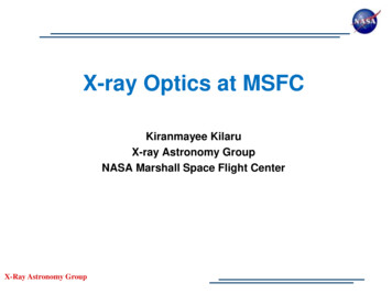
X-ray Optics at MSFC MSFC has been developingintegrated full-shell X-ray opticsfor 20 years Funded initially throughROSES/APRA program Fabrication Approach:Electroformed nickel replication Optics have been built forsatellite, rocket and balloonborne missions and for variousspin-off applicationsX-Ray Astronomy Group
X-ray Optics at MSFCOpticaldesign ctionMountingandalignmentAssemblyX-ray testingX-Ray Astronomy Group
Optical Design and Analysis Optical configuration – diameter, focallength, segment length, thickness Analytical and Monte-Carlo raytracingto characterize the on-axis and offaxis effective area, angular resolution,FOV Stray light analysis Coatings – Single and Multi-layers FEA- Mechanical- ThermalX-Ray Astronomy Group
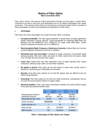
Electroformed Nickel ReplicationMandrel Preparation1. CNC machinemandrel fromaluminum bar2. Chemical cleanand activation& electroless nickel(EN) plate3. Diamond-turnto few 10s nmsurface, submicron figureaccuracy4.Superpolishto 0.3 – 0.4nmrms finishShell Fabrication6. Ultrasonic cleanand passivation7. Electroform NiCoshell onto mandrel( )X-Ray Astronomy Group(-)( )8. Separate opticfrom mandrel incold water bath5. Metrologyon mandrel
MSFC InfrastructureMandrel Diamond-TurningX-Ray Astronomy GroupMandrel Polishing
MSFC Infrastructure - MetrologyVLTP TalysurfSurface profile – Long Trace Profiler ( 2mm spatial wavelength), Form Talysurf surfaceprofiler ( 120 mm), Zygo interferometer (mandrel figure metrology) Surface roughness - Zygo NewView (spatial sampling range 0.04 to 11.8 microns) Circularity - Coordinate Measuring Machine Coating characterization - XRR (X-ray reflectometer for density, thickness androughness),Step ProfilerX-Ray Astronomy Group
MSFC Infrastructure - ReplicationX-Ray Astronomy Group
MSFC Infrastructure - Coatings Custom designed coating chambers for fullshell optics RF and DC magnetron sputter deposition Underway – Multilayer deposition chamber Active research in In-Situ stressmeasurement and analysisX-Ray Astronomy GroupRF SputterDepositionChamber
MSFC Infrastructure – Alignment & AssemblyMirror shell alignment and installation stations Shells are glued fromone end – less weightfor the support system,less obscuration General approach:Convert radialdisplacement intoazimuthal one The use of the clipsminimizes thedistortions due toepoxy shrinkingPre-glued clips minimize the distortions dueto epoxy shrinkageMikhail Gubarev et.al; Alignment system for full-shell replicated x-ray mirrors. Proc. SPIE 7360, EUV and X-RayX-RayAstronomyOptics:SynergyGroupbetween Laboratory and Space, 73600A (April 30, 2009); doi:10.1117/12.823848.
Alignment & Assembly - FEAo Sensitivity to radial displacementso Any radial distortion on one edge of theshell leads to distortions on other endof the shellDeformation maps for the 34 cm diameter, 60 cm lengthmonolithic shell supported with 12 points at the bottom of themirror. The shell is tilted by 1 microradian. The distortionscale is in microns.X-Ray Astronomy Group
MSFC Infrastructure – X-ray TestingStraylight test facility (SLTF) : 100m long vacuum tubeClean room facilityCan accommodate mirrors upto 1mdiameterPumped with cryopumps upto 10-7 torrX-ray and Cryogenic facility (XRCF): The XRCF is the world’s largestoptically clean cryogenic and X-raytest facility.The facility consists of a 520m-long Xray guide tube, an instrumentchamber, and two clean roomsIn addition to the large vacuumchamber, the facility has a smaller,more cost-effective cryogenic andcryogenic optical testing chamber forsubscale testing of smaller instrumentsX-Ray Astronomy Group
Optics ApplicationsX-Ray Astronomy Group
Full-Shell X-Ray OpticsFull-shell optics60 mm length 50 to 100 mm diameterDown to 50 m thickUp to 0.5 m diameterShells nested into a moduleX-Ray Astronomy GroupDown to 0.025 m diameter
Replicated X-ray Optic Projects at MSFCAstronomical applicationsPastHERO/Super HERO/HEROESART-XCCurrentIXPEIXPENon-astronomical applicationsMedical imagingMIXONeutron imagingFOXSI/FOXSI-2/FOXSI SMEXX-Ray Astronomy GroupMicroX
Flight X-ray Optics at MSFCIXPEART-XCFOXSIHERO2 - 105 - 305 - 1520 - 701000 cm2 at 3keV 455 cm2 at 8keV150 cm2 at 10 keV95 cm2 at 40 keV,50 cm2 at 60 keV37 (plus 1 spare)78Focal length (m)4.02.72.06.0Number of shellsper module2428714162 - 27250 - 15076 - 10350 - 94-IrIrIr180 - 250250 - 325250250Energy range (keV)Optics EffectiveareaNumber of ModulesShell diameterrange (mm)CoatingShell thickness(microns)X-Ray Astronomy Group
Spinoff Application: Neutron MicroscopyCollaboration: NASA MSFC, NIST, MIT Left:The FOXSI optic, with7 nested mirrorsProject aims to build the world’s first neutronRight: 2 parabolic sectionsmicroscopefrom one FOXSI shellto create aRe-envisioning and shaping the werefutureusedof neutron1:1 prototype neutronimagingmicroscopeCold neutron imaging requires similar graze angles asX-raysPotential for many commercial applicationsNeutron microscope prototype (2013)(shells are made from the parabolic segmentsof existing FOXSI mandrels)RequirementsMikhail V. Gubarev ; et.al; From x-ray telescopes toneutron focusing. Proc. SPIE 8147, Optics for EUV, XRay, and Gamma-Ray Astronomy V, 81470B (September30, 2011); doi:10.1117/12.897325.X-Ray Astronomy Group 10 shell pairs. Parabola-parabola 1 arc sec FWHM resolution
Spinoff Application: Radionuclide imagingMEDICAL IMAGING Animal imaging technology important for biomedicalscienceE.g., therapeutic development, disease study Non-invasive imaging plays a crucial role in anatomicalstudiesUltrasound: 200 μm resolutionCT & MRI: 25–50 μm resolutionFunctional & Metabolic studiesSPECT & PET: 1 mm fX-Ray Astronomy Group
Ongoing Improvements Typical resolutions are 25 arcsec HPD and 4-10 arcsec FWHM for ourproduction optics Efforts underway to improve the resolution include: Better quality mandrels Lower-stress electroforming Direct fabrication (& polishing) Post-fabrication figure correction More precise alignment and assembly The near-term goal is a few arcsec HPD and arcsec-level FWHMX-Ray Astronomy Group
Improved Mandrels: Zeeko Polishing Machine- The machine utilizes a “bonnet” technique inwhich an inflated rubber hemisphericaldiaphragm supports the polishing medium.- There are different “bonnet” sizes (20 mm,40 mm and 80 mm radii of curvature)- Thiscomputer-controlledpolishing processes leadsconvergence rate.deterministicto a high- Tool path generation (TPG) software had tobe developed.- Direct-fabrication of X-ray mirrorX-Ray Astronomy Group
Improved Mandrels: Zeeko Polishing MachineParametric wear pattern simulation enables amore efficient method of exploring the polishingparameter space.Wear rate is proportional to : Velocity of bonnet depends onMeasured wear function Spindle rotation Head attack angles Bonnet pressure depends on Schematic of bonnet modelInternal pressure of bonnetBonnet structural and mechanical propertiessurfaceParameter optimizationbonnetBonnet pressureSpindle speedTool OffsetTool offsetWear function characterizationRichardson-Lucy deconvolution algorithm small nonlinear correction (Tends to generate smoother edge transitions)Initial error map derived from metrologydata.RMS slope errors along x-axis are 8arcsec.X-Ray Astronomy GroupDerived feed rate map.Feed rates range from 1.35-20mm/min.Predicted result of polishing iteration.Predicted RMS slope errors are 0.6arcsecError map derived frommetrology data.RMS slope errors werereduced to 0.5 arcsec
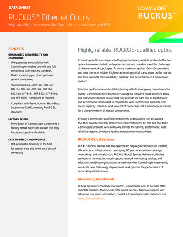
Mandrel Demonstrationbeforeafter500 nm10.7 nmSlope error ( 2 cm) (RMS)6.32 arcsec0.30 arcsecLow frequency ( 7 cm) slope error (RMS)2.66 arcsec0.09 arcsecMid frequency (2-7 cm) slope error (RMS)5.73 arcsec0.29 arcsecFigure error (St. Dev.)X-Ray Astronomy GroupMandrel 5xbetter than anymade withconventionalpolishing
Lower electroforming stresses: Pulsed Plating Reducestressvariationsinelectroforming through pulsed plating. Periodic reversal of polarity\duringelectroformingalternatesdeposition with selective etching,providing a finer grain structureand denser packing.Recent evidence shows that theshells plated this way are very lowstress and closer to the mandrelshape than with conventionalelectroforming.Circularity is key for a good FWHM - Pulsed plating of pure nickel recentlydemonstrated the micron-level circularity necessary for arc-second-levelFWHM resolution.X-Ray Astronomy Group
Full-Shell Direct FabricationBacking support system - A thin layer of backingmaterial (not shown) acts as an interface between themirror shell (red) and the stiff outer support clam-shell(gray). Technology development - figure and polish thin x-ray metaloptics directly Finite-Element Analysis - thickness 1.5 mm will be stableenough to be polished directly Metal substrates improve the mechanical stability, Single-point diamond turning instead of grinding process Computer controlled deterministic polishing In situ metrology system - Phase-Measuring Deflectometry (PMD): Deviations from perfect spacing offringe pattern measured at multiple phases provides an unambiguous measure of slope deviations ofthe mirror Developed fixtures to provide uniform back support to the entire shell during figuring and polishing Stiff outer shell and a thin layer of backing/interface material that goes between the mirror shelland the outer support High-viscosity liquids Pitch Granular materials - spherical glass beadsM. Gubarev ; B. Ramsey ; J. K. Kolodziejczak ; W. S. Smith ; J. Roche ; W. Jones ; C. Griffith ; T. Kester ; C. Atkins ; W. Arnold;X-Ray Astronomy GroupDirect fabrication of full-shell x-ray optics . Proc. SPIE 9603, Optics for EUV, X-Ray, and Gamma-Ray Astronomy VII, 96030V (September 4, 2015);doi:10.1117/12.2190020.
Mounting OptimizationPerformance vs. Axial Mounting Location The performance analysis of the cylindrical shell was performed, using both analytical methods and finiteelement analysis (FEA). Analytical methods were applied in Mathematica and detailed finite element models (FEMs) were madein ANSYS.Mounting 50-60% of the distancefrom center to edge minimizes theeffects of radial mounting forces onperformanceEndAnalytical modelsFEA simulationsJacqueline M. Roche et.al, Opto-mechanical analyses for performance optimization of lightweight grazing-incidence mirrors. Proc. SPIE 8861, Optics for EUV, X-Ray, and Gamma-Ray Astronomy VI, 88611G (September 26, 2013); doi:10.1117/12.2026884.X-Ray Astronomy Group
Alignment Strings approach – mirror is hung with strings Holding at the opposite end to the glue positions Equalizing the strings tension – self leveling and minimum distortionsOff loading weight to the stringsX-Ray Astronomy Group
Metal – Ceramic Hybrid ShellsCollaboration: NASA MSFC, SAO, ReliaCoat Plasma thermal spray technology To replace the high density Nickel withlight ceramic compound Ni density - 8.9 g/cm 3; Ceramiccompound density – 2.5 g/cm 3 Reduce the weight of the optic – keepthe advantages of electroform nickelreplicationX-Ray Astronomy Group
In-Situ Stress MeasurementNickel Stress at 500nm vs. Deposition Rate1400Optimal Deposition Rate for NearZero Stress120050010000Stress, MPa50040030020010008008.26 nm/min-500600 sition Rate, nm/minPreliminary measurements showing coating stress versusdeposition rate at fixed gas pressure. Inset shows stressversus coating thickness (nm) at fixed deposition rateX-Ray Astronomy Group
Figure Correction: Differential DepositionWhat Differential deposition is a technique for correcting figure errors inopticsSurface profilemetrologyHow Use physical vapor deposition to selectively deposit material on themirror surface to smooth out figure imperfectionsWhyDevelop correctionprofile “Hitmap” Can be used on any type of optic, full-shell or segmented, mounted orunmounted Can be used to correct a wide range of spatial errors. Could be used inSimulations – translationvelocity of shellconjunction with other techniques e.g. active optics.Differential depositionSurface profilemetrologyX-ray testingX-Ray Astronomy Group
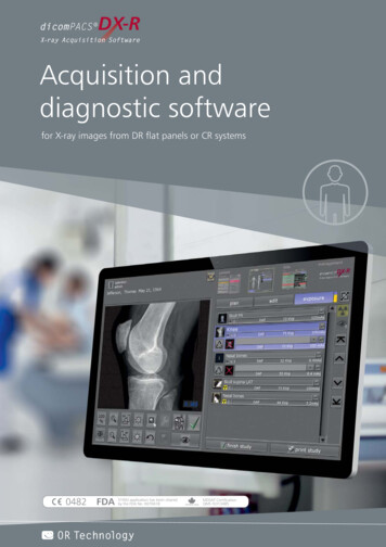
Process Sequence – Differential DepositionSimulated correction sequence showing parabolic axial figure profile before (top left) and after 3 stages of correction using abeam of FWHM 14mm, 5.2 mm and 1.7 mm respectively. The dotted line gives the desired figure and the solid line gives thefigure obtained at each stage. Overall, resolution improved from 7.8 arcsec to 0.9 arcsec HEW (2 bounce equivalent).X-Ray Astronomy Group
Coating systemsSputtering targetMaskMaskSputteringtargetX-ray mirrorSputtering head with coppermask positioned inside shellX-Ray Astronomy GroupSegmented glass opticTranslation stage
X-ray testing – pre-and post- differential coatingMarked areas - corrected azimuthal segmentsUncorrected area Plots shows intra-focus X-ray image (-40 mm)of the corrected shell Corrected segments are visually obviouscompared to the uncorrected in X-ray testingwith the CCDX-Ray Astronomy Group
X-ray testing – pre-and post- differential coatingA factor of 2improvement isachieved with onestage of correctionHigher frequency- correctionX-Ray Astronomy Group
Conclusion Full-Shell Optics at MSFC Electroform nickel replication has been used for past 20 years forsatellite, rocket and balloon-borne missions and for various spin-offapplications Improvements are underway Better quality mandrels Lower-stress electroforming Direct fabrication (& polishing) Post-fabrication figure correction More precise alignment and assemblyX-Ray Astronomy Group
the mirror Developed fixtures to provide uniform back support to the entire shell during figuring and polishing Stiff outer shell and a thin layer of backing/interface material that goes between the mirror shell and the outer support High-viscosity liq