Transcription
DUA1720-3AAA03 online.book Page 1 Monday, March 25, 2002 10:48 AMSuperStack 3Switch 4400Getting Started Guide3C172033C172043C17206http://www.3com.com/Part No. DUA1720-3AAA03Published March 2002
DUA1720-3AAA03 online.book Page 2 Monday, March 25, 2002 10:48 AM3Com Corporation5400 Bayfront PlazaSanta Clara, California95052-8145Copyright 2002, 3Com Technologies. All rights reserved. No part of this documentation may be reproducedin any form or by any means or used to make any derivative work (such as translation, transformation, oradaptation) without written permission from 3Com Technologies.3Com Technologies reserves the right to revise this documentation and to make changes in content from timeto time without obligation on the part of 3Com Technologies to provide notification of such revision orchange.3Com Technologies provides this documentation without warranty, term, or condition of any kind, eitherimplied or expressed, including, but not limited to, the implied warranties, terms or conditions ofmerchantability, satisfactory quality, and fitness for a particular purpose. 3Com may make improvements orchanges in the product(s) and/or the program(s) described in this documentation at any time.If there is any software on removable media described in this documentation, it is furnished under a licenseagreement included with the product as a separate document, in the hard copy documentation, or on theremovable media in a directory file named LICENSE.TXT or !LICENSE.TXT. If you are unable to locate a copy,please contact 3Com and a copy will be provided to you.UNITED STATES GOVERNMENT LEGENDIf you are a United States government agency, then this documentation and the software described herein areprovided to you subject to the following:All technical data and computer software are commercial in nature and developed solely at private expense.Software is delivered as “Commercial Computer Software” as defined in DFARS 252.227-7014 (June 1995) oras a “commercial item” as defined in FAR 2.101(a) and as such is provided with only such rights as areprovided in 3Com’s standard commercial license for the Software. Technical data is provided with limited rightsonly as provided in DFAR 252.227-7015 (Nov 1995) or FAR 52.227-14 (June 1987), whichever is applicable.You agree not to remove or deface any portion of any legend provided on any licensed program ordocumentation contained in, or delivered to you in conjunction with, this User Guide.Unless otherwise indicated, 3Com registered trademarks are registered in the United States and may or maynot be registered in other countries.3Com and SuperStack are registered trademarks of 3Com Corporation. The 3Com logo and CoreBuilder aretrademarks of 3Com Corporation.Intel and Pentium are registered trademarks of Intel Corporation. Microsoft, MS-DOS, Windows, and WindowsNT are registered trademarks of Microsoft Corporation. Novell and NetWare are registered trademarks ofNovell, Inc. UNIX is a registered trademark in the United States and other countries, licensed exclusivelythrough X/Open Company, Ltd.Netscape Navigator is a registered trademark of Netscape Communications.JavaScript is a trademark of Sun Microsystems.All other company and product names may be trademarks of the respective companies with which they areassociated.ENVIRONMENTAL STATEMENTIt is the policy of 3Com Corporation to be environmentally-friendly in all operations. To uphold our policy, weare committed to:Establishing environmental performance standards that comply with national legislation and regulations.Conserving energy, materials and natural resources in all operations.Reducing the waste generated by all operations. Ensuring that all waste conforms to recognized environmentalstandards. Maximizing the recyclable and reusable content of all products.Ensuring that all products can be recycled, reused and disposed of safely.Ensuring that all products are labelled according to recognized environmental standards.Improving our environmental record on a continual basis.End of Life Statement3Com processes allow for the recovery, reclamation and safe disposal of all end-of-life electronic components.Regulated Materials Statement3Com products do not contain any hazardous or ozone-depleting material.Environmental Statement about the DocumentationThe documentation for this product is printed on paper that comes from sustainable, managed forests; it isfully biodegradable and recyclable, and is completely chlorine-free. The varnish is environmentally-friendly, andthe inks are vegetable-based with a low heavy-metal content.
DUA1720-3AAA03 online.book Page 3 Monday, March 25, 2002 10:48 AMCONTENTSABOUT THIS GUIDEConventions 8Related Documentation 9Accessing Online DocumentationProduct Registration 10Documentation Comments 1019INTRODUCING THESUPERSTACK 3 SWITCH 4400About the Switch 4400 12Summary of Hardware Features 12Summary of Software Features 13Switch 4400 — Front View Detail 1410BASE-T/ 100BASE-TX Ports 15LEDs 15Switch 4400 — Rear View Detail 17Power Socket 18Redundant Power System Socket 18Console Port 18Expansion Module Slots 18Default Settings 192INSTALLINGTHESWITCHPackage Contents 22Choosing a Suitable Site 22Rack-mounting 23Placing Units On Top of Each Other 25Stacking Units 25The Power-up Sequence 26Powering-up the Switch 4400 26
DUA1720-3AAA03 online.book Page 4 Monday, March 25, 2002 10:48 AMChecking for Correct Operation of LEDsConnecting a Redundant Power SystemChoosing the Correct Cables 273SETTING UPFOR2627MANAGEMENTSetting Up Overview 30IP Configuration 30Preparing for Management 32Initial Switch Setup 32Manual Setup 33Connecting to a Front Panel Port 33Connecting to the Console Port 35Automatic Setup 38Using 3Com Network Supervisor 38Connecting to the Console Port 38Methods of Managing a Switch 41Command Line Interface Management 41Web Interface Management 42SNMP Management 42Setting Up Command Line Interface ManagementCLI Management via the Console Port 43CLI Management over the Network 43Setting Up Web Interface Management 44Pre-requisites 44Web Management Over the Network 44Setting Up SNMP Management 45Pre-requisites 45Default Users and Passwords 46Changing Default Passwords 464PROBLEM SOLVINGSolvingSolvingSolvingSolvingProblems Indicated by LEDs 48Hardware Problems 49Communication Problems 50Software Upgrade Problems 5143
DUA1720-3AAA03 online.book Page 5 Monday, March 25, 2002 10:48 AMASAFETY INFORMATIONImportant Safety Information 54L’information de Sécurité Importante 55Wichtige Sicherheitsinformationen 57BPIN-OUTSNull Modem Cable 59PC-AT Serial Cable 59Modem Cable 60RJ-45 Pin Assignments 60CTECHNICAL SPECIFICATIONSSwitch 4400(24-port) 63Switch 4400(48-port) 65DTECHNICAL SUPPORTOnline Technical Services 67World Wide Web Site 673Com Knowledgebase Web Services 673Com FTP Site 68Support from Your Network Supplier 68Support from 3Com 68Returning Products for Repair 70INDEXREGULATORY NOTICES
DUA1720-3AAA03 online.book Page 6 Monday, March 25, 2002 10:48 AM
DUA1720-3AAA03 online.book Page 7 Monday, March 25, 2002 10:48 AMABOUT THIS GUIDEThis guide provides all the information you need to install and use aSuperStack 3 Switch 4400 in its default state.This guide is intended for use with Switch 4400 models: 3C17203 and 3C17206 — 24 10BASE-T/100BASE-TX ports 3C17204 — 48 10BASE-T/100BASE-TX portsAll procedures described in this guide apply to all models.The guide is intended for use by network administrators who areresponsible for installing and setting up network equipment;consequently, it assumes a basic working knowledge of LANs (Local AreaNetworks).If the information in the release notes that are shipped with your productdiffer from the information in this guide, follow the instructions in therelease notes.Most user guides and release notes are available in Adobe AcrobatReader Portable Document Format (PDF) or HTML on the 3ComWorld Wide Web site:http://www.3com.com/
DUA1720-3AAA03 online.book Page 8 Monday, March 25, 2002 10:48 AM8ABOUT THIS GUIDEConventionsTable 1 and Table 2 list conventions that are used throughout this guide.Table 1 Notice IconsIconNotice TypeDescriptionInformation noteInformation that describes important features orinstructionsCautionInformation that alerts you to potential loss of data orpotential damage to an application, system, or deviceWarningInformation that alerts you to potential personal injuryTable 2 Text ConventionsConventionDescriptionScreen displays This typeface represents information as it appears on thescreen.SyntaxThe word “syntax” means that you must evaluate the syntaxprovided and then supply the appropriate values for theplaceholders that appear in angle brackets. Example:To change your password, use the following syntax:system password password CommandsIn this example, you must supply a password for password .The word “command” means that you must enter thecommand exactly as shown and then press Return or Enter.Commands appear in bold. Example:To display port information, enter the following command:bridge port detailWhen you see the word “enter” in this guide, you must typesomething, and then press Return or Enter. Do not pressReturn or Enter when an instruction simply says “type.”Keyboard key names If you must press two or more keys simultaneously, the keynames are linked with a plus sign ( ). Example:The words “enter”and “type”Words in italicsPress Ctrl Alt DelItalics are used to: Emphasize a point. Denote a new term at the place where it is defined in thetext. Identify menu names, menu commands, and softwarebutton names. Examples:From the Help menu, select Contents.Click OK.
DUA1720-3AAA03 online.book Page 9 Monday, March 25, 2002 10:48 AMRelated DocumentationRelatedDocumentation9In addition to this guide, each Switch documentation set includes thefollowing: SuperStack 3 Switch Implementation GuideThis guide contains information on the features supported by yourSwitch and how they can be used to optimize your network. It issupplied in PDF format on the CD-ROM that accompanies the Switch. SuperStack 3 Switch Management Quick Reference GuideThis guide contains a summary of the web interface and commandline interface commands for the Switch. SuperStack 3 Switch Management Interface Reference GuideThis guide provides detailed information about the web interface andcommand line interface that enable you to manage the Switch. It issupplied in HTML format on the CD-ROM that accompanies theSwitch. Release NotesThese notes provide information about the current software release,including new features, modifications, and known problems.There are other publications you may find useful, such as:Accessing OnlineDocumentation Documentation accompanying the Advanced Redundant Powersystem. Documentation accompanying the Expansion Modules. Documentation accompanying 3Com Network Supervisor. This issupplied on the CD-ROM that accompanies the Switch.The CD-ROM supplied with your Switch contains the following onlinedocumentation: SuperStack 3 Switch Implementation Guide (PDF format) SuperStack 3 Switch Management Interface Reference Guide (HTMLformat).1 To access the documentation insert the CD-ROM into your CD-ROMdrive. If your PC has auto-run enabled, a splash screen will be displayedautomatically.2 Select the Documentation section from the contents page.
DUA1720-3AAA03 online.book Page 10 Monday, March 25, 2002 10:48 AM10ABOUT THIS GUIDEIf the online documentation is to be accessed from a local drive or server,you will need to access the CD-ROM contents via the root directory andcopy the files from the CD-ROM to a suitable directory. The HTML Reference Guide is stored in the Docs/reference directoryon the CD-ROM. The documentation is accessed using thecontents.htm file. The PDF Implementation Guide is stored in theDocs/implementation directory of the CD-ROM.3Com recommends that you copy the Docs/reference directory as awhole to maintain the structure of the files.ProductRegistrationYou can register your SuperStack 3 Switch 4400 on the 3Com Web site:DocumentationCommentsYour suggestions are very important to us. They will help make ourdocumentation more useful to you. Please e-mail comments about thisdocument to 3Com pddtechpubs comments@3com.comPlease include the following information when commenting: Document title Document part number (on the title page) Page number (if appropriate)Example:Part Number DUA 1720-3AAA0xSuperStack 3 Switch 4400 Getting Started GuidePage 21
DUA1720-3AAA03 online.book Page 11 Monday, March 25, 2002 10:48 AM1INTRODUCING THESUPERSTACK 3 SWITCH 4400This chapter contains introductory information about the Switch 4400and how it can be used in your network. It covers summaries of hardwareand software features and also the following topics: About the Switch 4400 Switch 4400 — Front View Detail Switch 4400 — Rear View Detail Default Settings
DUA1720-3AAA03 online.book Page 12 Monday, March 25, 2002 10:48 AM12CHAPTER 1: INTRODUCING THE SUPERSTACK 3 SWITCH 4400About the Switch4400Summary ofHardware FeaturesThe Switch 4400 is a stackable 10/100 Mbps device and provideshigh-performance work groups with a backbone to server connection.The Switch 4400 allows Cascade, Gigabit Ethernet or Fast Ethernet Fiberconnections when expansion modules are installed in the expansion slotson the rear of the unit. You can also add the Switch 4400 to anySuperStack system as your network grows.Table 3 summarizes the hardware features that are supported by theSwitch 4400.Table 3 Hardware featuresFeatureSwitch 4400Addresses Up to 8000 supported Up to 64 permanent entries Supported on all ports Auto MDI/MDI-XAuto-negotiationForwarding ModesStore and ForwardDuplex ModesHalf and full duplex on all front panel portsFlow ControlIn full duplex operation all ports are supportedSmart Auto-sensingSupported on all portsTraffic PrioritizationSupported (IEEE 802.ID): 4 queues per portEthernet and Fast Ethernet Auto-negotiating 10BASE-T/100BASE-TX portsPortsRPS SupportConnects to SuperStack 3 Advanced RedundantPower System (ARPS) (3C16071B)Mounting19-inch rack or stand-alone mounting
DUA1720-3AAA03 online.book Page 13 Monday, March 25, 2002 10:48 AMAbout the Switch 4400Summary of SoftwareFeatures13Table 4 summarizes the software features that are supported by theSwitch 4400.Table 4 Software featuresFeatureSwitch 4400Automatic IPConfigurationSupportedResilient LinksSupportedAggregated LinksSupported stack-wideBroadcast Storm ControlSupportedVirtual LANs (VLANs)Support for up to 60 VLANs using the IEEE 802.1QstandardMulticast Filtering 128 Multicast filter groups supported IGMP filtering supportedSpanning Tree Protocol(802.1D-1998)SupportedRoving Analysis PortSupportedRapid Spanning TreeProtocol (802.1w)SupportedWebcache SupportSupported*Quality of Service (QoS)Supported*RMONFour groups supported: Statistics, History, Alarms,EventEmail Notification ofEventsSupportedManagementWeb interface, command line interface, and SNMPsupportedPort SecurityDisconnect Unauthorized Device (DUD) supported*Webcache support and Quality of Service (QoS) are not available on the SuperStack 3 Switch4400 SE unless the product has been upgraded to the 4400 enhanced feature set.For information about managing the software features of the Switch,refer to the “SuperStack 3 Switch Management Interface ReferenceGuide” on the CD-ROM that accompanies the Switch.
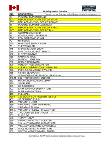
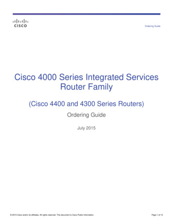
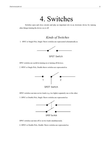
DUA1720-3AAA03 online.book Page 14 Monday, March 25, 2002 10:48 AM14CHAPTER 1: INTRODUCING THE SUPERSTACK 3 SWITCH 4400Switch 4400 —Front View DetailFigure 1 Switch 4400 / 4400 SE — front view 1Figure 2 Switch 4400 / 4400 SE — front view 2The appearance of the overlays in Figure 1 and Figure 2 differ but thefunctionality is identical for both Switches.
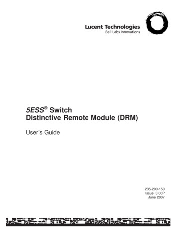
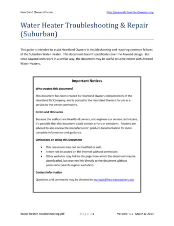
DUA1720-3AAA03 online.book Page 15 Monday, March 25, 2002 10:48 AMSwitch 4400 — Front View Detail15Figure 3 Switch 4400 (48-port) — front viewWARNING: RJ-45 Ports. These are shielded RJ-45 data sockets. They cannotbe used as standard traditional telephone sockets, or to connect the unit to atraditional PBX or public telephone network. Only connect RJ-45 dataconnectors, network telephony systems, or network telephones to thesesockets.Either shielded or unshielded data cables with shielded or unshieldedjacks can be connected to these data sockets.10BASE-T/100BASE-TX PortsThe Switch has 24 or 48 auto-negotiating 10BASE-T/100BASE-TX portsconfigured as Auto MDIX (cross-over). These ports automatically providethe appropriate connection. Alternatively, you can manually set theseports to 10BASE-T half duplex, 10BASE-T full duplex, 100BASE-TX halfduplex or 100BASE-TX full duplex. The maximum segment length is100 m (328 ft) over Category 5 twisted pair cable.LEDsTable 5 lists LEDs visible on the front of the Switch, and how to read theirstatus according to color. For information on using the LEDs for problemsolving, see “Solving Problems Indicated by LEDs” on page 48.
DUA1720-3AAA03 online.book Page 16 Monday, March 25, 2002 10:48 AM16CHAPTER 1: INTRODUCING THE SUPERSTACK 3 SWITCH 4400Table 5 LED behaviorLEDColorIndicatesPort Status LEDsPacket GreenFull duplex packets are being transmitted/received on theport.YellowHalf duplex packets are being transmitted/received on theport.OffNo packets are being transmitted/received on the port.Status GreenA high speed (100 Mbps) link is present, and the port isenabled.Green flashing A high speed (100 Mbps) link is present, but the port isdisabled.YellowA low speed (10 Mbps) link is present, and the port isenabled.Yellow flashing A low speed (10 Mbps) link is present, but the port isdisabled.OffNo link is present.Module Packet LEDsGreenFull duplex activity being received or transmittedYellowHalf duplex activity being received or transmittedOffNo activityModule Status LEDsGreenThe Module is installed and supported. The Link Status hasbeen determined, and the port is enabled.Green flashing The Module is installed and supported. The Link Status hasbeen determined, but the port is disabled.YellowThe Module is installed and supported. The Link status hasnot been determined or there is no Link for a single portModule.Yellow flashing A Module is installed, however, it is not supported.OffThe Module is not installed.Unit LEDs1–8GreenWhen the Switch forms a stack with other Switch 4400units, the LED indicates the position of the unit in the stackand that a link is present.When the Switch is stand-alone and not part of a stack, LED1 is on.
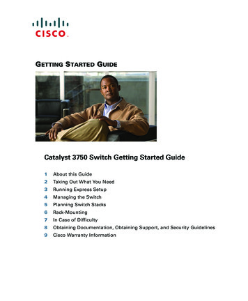
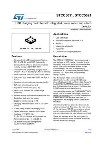
DUA1720-3AAA03 online.book Page 17 Monday, March 25, 2002 10:48 AMSwitch 4400 — Rear View DetailLEDColor17IndicatesGreen rotating When a software upgrade is in progress, the Unit LEDs of theunit that is being upgraded flash on and off in the followingsequence —1,2,4,6,8,7,5,3 (24-port)1,2,3,4,8,7,6,5 (48-port)Green flashing The Switch physically forms a stack with other Switch 4400units, but cannot be managed as part of that stack until allunits have been upgraded to software version 2.0 or later.OffA fault has occurred.Power/Self Test LEDGreenThe Switch is powered-up and operating normally.Green flashing The Switch is either downloading software or is initializing(which includes running a Power On Self Test).Switch 4400 — RearView DetailYellowThe Switch has failed its Power On Self Test.OffThe Switch is not receiving power or there is a fault with thePower Supply Unit.Figure 4 Switch 4400 / 4400 SE — rear view 1
DUA1720-3AAA03 online.book Page 18 Monday, March 25, 2002 10:48 AM18CHAPTER 1: INTRODUCING THE SUPERSTACK 3 SWITCH 4400Figure 5 Switch 4400 / 4400 SE — rear view 2The appearance of the Switches shown in Figure 1 and Figure 2 differ butthe functionality is identical for both Switches.Power SocketThe Switch automatically adjusts its power setting to any supply voltagein the range 90-260 VAC.Redundant PowerSystem SocketTo protect against internal power supply failure, you can use this socketto connect a Switch 4400 to a SuperStack 3 Advanced Redundant PowerSystem (RPS). See “Connecting a Redundant Power System” on page 27.Console PortThe console port allows you to connect a terminal and perform remote orlocal out-of-band management. The console port uses a standard nullmodem cable and is set to auto-baud, 8 data bits, no parity and 1 stopbit.Expansion ModuleSlotsYou can use these slots to install Expansion Modules. These allow theSwitch to support various forms of connection and add extra functionalityto your Switch. Contact your supplier for more information.WARNING: When an Expansion Module is not installed, ensure theblanking plate is fitted by tightening all screws with a suitable tool.
DUA1720-3AAA03 online.book Page 19 Monday, March 25, 2002 10:48 AMDefault SettingsDefault Settings19Table 6 shows the default settings for the Switch 4400:Table 6 Default SettingsFeatureSwitch 4400Automatic IP ConfigurationEnabledPort StatusEnabledPort Speed10/100 Mbps ports are auto-negotiatedDuplex ModeAll fixed 10BASE-T and 100BASE-TX ports areauto-negotiatedFlow Control Enabled in half duplex Auto-negotiated in full duplexBroadcast Storm ControlEnabledVirtual LANs (VLANs)All ports belong to the untagged Default VLAN(VLAN 1) with 802.1Q learning operationalIP Multicast FilteringFiltering enabledRapid Spanning Tree Protocol EnabledFast Start: Enabled on front panel ports Disabled on rear panel portRMON AlarmEnabledSmart Auto-SensingEnabledWebcache SupportDisabledQuality of Service (QoS)All ports prioritize NBX VoIP traffic (LAN and IP).All ports set to “best effort” for all other traffic.Webcache support and Quality of Service (QoS) are not available on theSuperStack 3 Switch 4400 SE unless the product has been upgraded tothe 4400 enhanced feature set.If you initialize a Switch unit by selecting System Control Initialize inthe Web interface or by entering system control initialize inthe Command Line Interface, the following settings are retained to allowyou to connect to and manage the Switch: IP Address Subnet Mask Default Router
DUA1720-3AAA03 online.book Page 20 Monday, March 25, 2002 10:48 AM20CHAPTER 1: INTRODUCING THE SUPERSTACK 3 SWITCH 4400
DUA1720-3AAA03 online.book Page 21 Monday, March 25, 2002 10:48 AM2INSTALLING THE SWITCHThis chapter contains the information you need to install and set up theSwitch 4400. It covers the following topics: Package ContentsChoosing a Suitable SiteRack-mountingPlacing Units On Top of Each OtherThe Power-up SequenceWARNING: Safety Information. Before installing or removing anycomponents from the Switch 4400 or carrying out any maintenanceprocedures, you must read the safety information provided in Appendix Aof this guide.AVERTISSEMENT: Consignes de sécurité. Avant d'installer ou d'enlevertout composant du Switch 4400 ou d'entamer une procédure demaintenance, lisez les informations relatives à la sécurité qui se trouventdans l'Appendice A de ce guide.VORSICHT: Sicherheitsinformationen. Bevor Sie Komponenten ausdem Switch 4400 entfernen oder dem Switch 4400 hinzufuegen oderInstandhaltungsarbeiten verrichten, lesen Sie die Sicherheitsanweisungen,die in Appendix A (Anhang A) in diesem Handbuch aufgefuehrt sind.
DUA1720-3AAA03 online.book Page 22 Monday, March 25, 2002 10:48 AM22CHAPTER 2: INSTALLING THE SWITCHPackage ContentsChoosing a SuitableSite Switch unit CD-ROM Getting Started Guide (this guide) Management Quick Reference Guide Release Notes Unit Information Labels Warranty Information Power Cord 2 x Mounting brackets 4 x Screws 4 x Rubber feetThe Switch is suited for use on a desktop, either free standing ormounted in a standard 19-inch equipment rack. Alternatively, the Switchcan be mounted in a wiring closet or equipment room, as an aggregatorfor other Hubs and Switches. A rack-mounting kit containing twomounting brackets is supplied with the Switch.CAUTION: Ensure that the ventilation holes are not obstructed.When deciding where to position the Switch, ensure that: Cabling is located away from: sources of electrical noise such as radios, transmitters andbroadband amplifiers.power lines and fluorescent lighting fixtures The Switch is accessible and cables can be connected easily. Water or moisture cannot enter the case of the Switch. Air-flow is not restricted around the Switch or through the vents in theside of the Switch. 3Com recommends that you provide a minimum of25mm (1in.) clearance. Air flow around the Switch does not exceed 40 C (104 F).If the Switch is installed in a 19-inch rack or closed assembly its local airtemperature may be greater than room ambient temperature.
DUA1720-3AAA03 online.book Page 23 Monday, March 25, 2002 10:48 AMRack-mountingRack-mounting23 The air is as free from dust as possible. The unit is installed in a clean, air conditioned environment. No more than eight Switch units are placed on top of one another, ifthe units are free-standing. The Switch is situated away from sources of conductive (electrical)dust, for example laser printers. The AC supply used by the Switch is separate to that used by unitsthat generate high levels of AC noise, for example air conditioningunits and laser printers.The Switch 4400 is 1U high and will fit in most standard 19-inch racks.CAUTION: Disconnect all cables from the Switch before continuing.Remove all self adhesive pads from the underside of the Switch if theyhave been fitted.To rack-mount your Switch:1 Place the Switch the right way up on a hard flat surface, with the frontfacing towards you.2 Locate a mounting bracket over the mounting holes on one side of theSwitch, as shown in Figure 6.
DUA1720-3AAA03 online.book Page 24 Monday, March 25, 2002 10:48 AM24CHAPTER 2: INSTALLING THE SWITCHFigure 6 Fitting a bracket for rack-mounting3 Insert the two screws and tighten with a suitable screwdriver.You must use the screws supplied with the mounting brackets. Damagecaused to the unit by using incorrect screws invalidates your warranty.4 Repeat steps 2 and 3 for the other side of the Switch.5 Insert the Switch into the 19-inch rack and secure with suitable screws(not provided). Ensure that ventilation holes are not obstructed.6 Connect network cabling.7 Finally place a unit information label on the unit in an easily accessibleposition. The unit information label shows the following: The 3Com product name of the Switch The 3Com 3C number of the Switch The unique MAC address (Ethernet address) of the Switch The serial number of the SwitchYou may need this information for fault reporting purposes.
DUA1720-3AAA03 online.book Page 25 Monday, March 25, 2002 10:48 AMPlacing Units On Top of Each OtherPlacing Units OnTop of Each Other25If the Switch units are free-standing, up to eight units can be placed oneon top of the other. If you are mixing a variety of SuperStack 3 Switchand Hub units, the smaller units must be positioned at the top.If you are placing Switch units one on top of the other, you must use theself-adhesive rubber pads supplied. Apply the pads to the underside ofeach Switch, sticking one in the marked area at each corner. Place theSwitch units on top of each other, ensuring that the pads of the upperunit line up with the recesses of the lower unit.Stacking UnitsSwitch 4400 units can be stacked together and then treated as a singlemanageable unit with one IP address. Any combination of 24-port and48-port units is allowed in a single stack, as long as the total number offront panel ports does not exceed the limit of 192 ports. The followingcombinations are allowed: 4 x 48-port Switches 3 x 48-port Switches and 2 x 24-port Switches 2 x 48-port Switches and 4 x 24-port Switches 1 x 48-port Switch and 6 x 24-port Switches 8 x 24-port SwitchesUsing the Expansion Module slot at the rear of the Switch, you can stackSwitch units together in two ways: The SuperStack 3 Switch Cascade Stacking Kit (3C17227) consists oftwo Cascade Modules and a Cascade Cable. This kit allows you toconnect two Switch 4400 units together. The SuperStack 3 Cascade Extender Kit (3C17228) consists of oneCascade Module, one Cascade Cable and one Cascade Extender Unit.This kit allows you to connect any of the combinations of Switch 4400units shown in “Stacking Units” on page 25. Each Cascade ExtenderKit enables you to add one additional Switch to your stack.For more information contact your supplier, and refer to the userdocumentation that accompanies these Cascade Kits.CAUTION: The SuperStack 3 Switch 4400 SE cannot be stacked withnon-SE Switches unless you are running the 4400 enhanced feature set.
DUA1720-3AAA03 online.book Page 26 Monday, March 25, 2002 10:48 AM26CHAPTER 2: INSTALLING THE SWITCH3Com recommends that you initialize a Switch 4400 unit that haspreviously been used elsewhere in your network before you add it to anexisting stack. If you do not initialize the unit, problems may be caused byconflicting Switch configurations.When the Switch 4400s are stacked together they are assigned a unitnumber from bottom-to-top for management purposes. When furtherswitches are added to the stack, they can be positioned at the bottom ofthe stack or at the top. Either way, the Switch management software willre-order the Switch unit numbers into a logical order again (from bottomto top).The Power-upSequencePowering-up theSwitch 4400The following sections describe how to get your Switch 4400powered-up and ready for operation.Use the following sequence of steps to power-up the Switch.1 Plug the power cord into the power socket at the rear of the Switch.2 Plug the other end of the power cord into your power outlet.The Switch powers-up and runs through its Power On Self Test (POST),which takes approximately 10 seconds.Checking for CorrectOperation of LEDsDuring the Power On Self Test, all ports on the Switch are disabled andthe LEDs light in a set sequence.When the POST has completed, check the Power/Self Test LED to makesure that your Switch is operating correctly. Table 7 shows possible colorsfor the LED.Table 7Power/Self
ABOUT THIS GUIDE This guide provides all the information you need to install and use a SuperStack 3 Switch 4400 in its default state. This guide is intended for use with Switch 4400 models: 3C17203 and 3C17206 — 24 10BASE-T/100BASE-TX ports 3C17204 — 48 10BASE-T/100BASE-TX ports Al