Transcription
OPERATOR’S MANUALCE SPECIFICATIONSSpecifications . 2Introduction . 3Machine Components . 4Machine Controls . 6Safety . 8Safety Rules And Precautions . 8Fall Protection Notice . 10Safety and Instructional Decals . 12Operation . 14Prestart . 14Diesel Engine . 15Lower Control Operation And Checks . 16Upper Control Operation and Checks . 17Set Maintenance Lock . 20Inspect Machine . 20Extending the Roll-out Extension Deck . 21Lowering The Platform Railings . 22Emergency Systems And Procedures . 24Outriggers . 25Shutdown Procedure . 25Maintenance . 26Lubrication Diagram . 27ART ES:Serial # 9001100 - UpSerial # 9015000 - UpSerial # 8804100 - UpSerial # 11100600 - UpSerial # 9801100 - UpSerial # 9901200 - UpSerial # 10001200 - Up90886 R2October 2008Prestart Inspection . 28Monthly Inspection . 29Quarterly Inspection . 30Annual Inspection . 31Troubleshooting . 32Serial Plate . 32Transport and Lifting Instructions. 34Lifting Instructions . 34Unloading Procedures . 35Towing the Machine . 36Disengage Brakes Before Towing or Winching . 36Engage Brakes Before Driving . 36
SPECIFICATIONS1532ES1932ES2033ES6.50 m4.50 m7.71 m5.71 m7.98 m5.98 m9.8 m7.98 m1.90 mNA2.10 mNA2.06 m1.94 m2.19 m1.94 m2272 kg2226 kg2363 kg2226 kg113 kg113 kg113 kg113 kg0.96 x 1.68 m1.03 m0.96 x 1.68 m1.03 m0.81 x 3.36 m1.10 m0.81 x 3.36 m1.10 mWorking Height*Platform HeightStowed HeightRails UpRails Folded DownMaximum Number of OccupantsLift Capacity (Evenly Distributed)Rollout Deck CapacityPlatform DimensionsWith Roll-Out Deck RetractedGuard Rail HeightToe Board HeightRollout Deck LengthOverall LengthOverall WidthWheel BaseWheel TrackTurning RadiusInsideOutsideGround ClearanceMachine Weight** (Unloaded) (Approx.)Drive System (Proportional)Drive Speed (Platform Elevated - Forward)Drive Speed (Platform Lowered)Lift/Lower Speed (Approx.)GradeabilityGround Pressure/Wheel (Maximum)Wind Speed (Maximum)19 cm19 cm15 cm15 cm0.91 m0.91 m1.0 m1.0 m1.83 m0.80 m1.27 m0.70 m1.83 m0.80 m1.27 m0.70 m2.49 m0.84 m1.8 m0.70 m2.49 m0.84 m1.8 m0.70 m5 cm1.8 m5 cm1.8 m0 cm2.0 m0 cm2.0 m0.6.8 m1236 kg6.8 m1390 kg8.9 cm1731 kg8.9 cm42109 kg0 - 0.8 km/h0 - 0.64 km/h0 - 3.7 km/h17 sec / 20 sec17 sec / 20 sec25% / 14 25% / 14 0 - 2.7 km/h27 sec / 35 sec27 sec / 35 sec24% / 13.5 24% / 13.5 7.4 kg/cm²0 m/sMain SystemLift SystemInputOutputBatteriesElectric MotorFour 6 Volt deep-cycle8.08 kg/cm²0 m/s9.07 kg/cm²0 m/s40.6 x 12.7 cm102 - 115 Nm190 bar190 bar190 bar190 bar131 bar62 bar180 bar62 bar166 bar62 bar180 bar69 barSteerHydraulic Fluid CapacityPower System – VoltageBattery Charger7.9 kg/cm²0 m/s35.56 cm x 11.43 cm102 - 115 NmTire Size-Standard (Solid, non-marking rubber)Wheel Lug Nut TorqueHydraulic Pressure2633ES11.36 liters11.36 liters24 Volts DC24 Volts DC100-220 Volt AC, 50/60 Hz, 5.6 Amp11.36 liters11.36 liters24 Volts DC24 Volts DC100-220 Volt AC, 50/60 Hz, 5.6 Amp24 Volt DC, 25 Amps Tapering,24 Volt DC, 25 Amps Tapering,Timed Shutoff220 Amp hours @ 20 hour rating4.0 h.p. (2.98 kW): 3000 r.p.m.Timed Shutoff220 Amp hours @ 20 hour rating4.0 h.p. (2.98 kW): 3000 r.p.m.Meets requirements of CE.*Metric equivalent of working height adds 2 m (6.6 ft.) to platform height.**Weight may increase with certain options or country standards.Operator's Manual - 2591RT 3391RT 4191RT: CE ModelsPage 2September 2008
SPECIFICATIONSWorking Height*Platform HeightStowed HeightRails UpRails Folded DownMaximum Number of Occupants 0 m/s wind12.5 m/s windLift Capacity (Evenly Distributed)Rollout Deck CapacityPlatform DimensionsWith Roll-Out Deck extendedWith Roll-Out Deck RetractedGuard Rail HeightToe Board HeightRollout Deck LengthOverall LengthOverall WidthWheel BaseWheel TrackTurning RadiusInsideOutsideGround ClearanceMachine Weight** (Unloaded) (Approx.)Drive System (Proportional)Drive Speed (Platform Elevated - Forward)Drive Speed (Platform Lowered)Lift/Lower Speed (Approx.)GradeabilityGround Pressure/Wheel (Maximum)Wind Speed (Maximum)2047ES2647ES3247ES7.98 m5.98 m9.80 m7.8 m11.60 m9.60 m2.13 m1.65 m2.27 m1.81 m2.45 m1.97 m311.67 kg3N/A454 kg2N/A318 kg113 kg113 kg113 kg3.39 m3.39 m3.39 m2.31 m1.10 m2.31 m1.10 m2.31 m1.10 m15.2 cm15.2 cm15.2 c m1.07 m1.07 m1.07 m2.51 m1.19 m1.80 m1.04 m2.51 m1.19 m1.80 m1.04 m2.51 m1.19 m1.8 m1.04 m0 cm2.4 m0 cm2.4 m0 cm2.4 m8.9 cm2019 kg8.9 cm2404 kg8.9 cm2717 kg0 - 0.69 km/h34/35 sec.25%0 - 4.0 km/h36/35 sec.25%42/45 sec.23%12.7 kg/cm²12.5 m/s14.0 kg/cm²0 m/s14.9 kg/cm²0 m/s40.6 cm D x 12.7 cm W102 - 115 NmTire Size-Standard (Solid, non-marking rubber)Wheel Lug Nut TorqueHydraulic PressureMain SystemLift SystemSteerHydraulic Fluid CapacityPower System – VoltageBattery Charger190 bar207 bar207 bar172 bar76 bar172 bar76 bar141 bar76 bar17.0 liters24 Volts DC100-220 Volt AC, 50/60 Hz, 5.6 Amp17.0 liters24 Volts DC17.0 liters24 Volts DCInputOutputBatteriesElectric MotorFour 6 Volt deep-cycle24 Volt DC, 25 Amps Tapering,Timed Shutoff240 Amp hours @ 20 hour rating4.0 h.p. (2.98 kW): 3000 r.p.m.Meets requirements of CE.*Metric equivalent of working height adds 2 m (6.6 ft.) to platform height.**Weight may increase with certain options or country standards.September 2008Operator's Manual - 2591RT 3391RT 4191RT: CE ModelsPage 3
INTRODUCTIONThis Operator’s Manual has been designed to provide you, thecustomer, with the instructions and operating procedures essentialto properly and safely operate your MEC Self-Propelled Scissors forits intended purpose of positioning personnel, along with theirnecessary tools and materials to overhead work locations.The operator’s manual must be read and understood prior tooperating your MEC self-propelled scissors. The user/operatorshould not accept operating responsibility until he/she hasread and understands the operator’s manual as well as havingoperated the MEC scissor lift under supervision of an authorized, trained and qualified operator.It is essential that the operator of the aerial work platform isnot alone on the workplace during operation.Modifications of this machine from the original design andspecifications without written permission from MEC are strictlyforbidden. A modification may compromise the safety of themachine, subjecting operator(s) to serious injury or death.Your MEC Scissor Lift has been designed, built, and tested toprovide safe, dependable service. Only authorized, trained andqualified personnel should be allowed to operate or service themachine.MEC, as manufacturer, has no direct control over machine application and operation. Proper safety practices are the responsibility ofthe user and all operating personnel.If there is a question on application and/or operation contact:MEC Aerial Platform Sales Corp.1775 Park Street, Suite 77 Selma, CA 93662 USAPh: 1-800-387-4575 559-891-2488 Fax: 559-891-2448www.mecawp.comOperator's Manual - 2591RT 3391RT 4191RT: CE ModelsPage 4September 2008
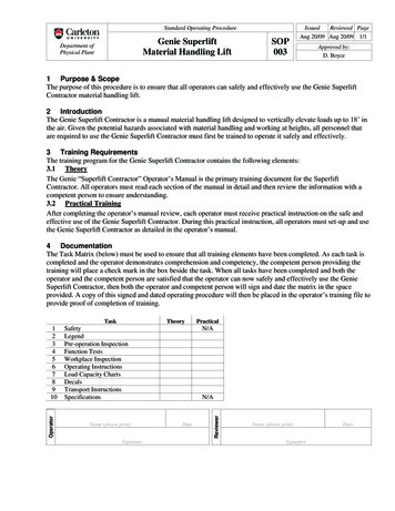
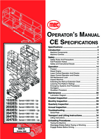
Machine ComponentsControl BoxPlatformMain Platform DeckControl kBeams2033ES - 2633ESControl BoxPlatformRoll-out Extension perLift 32ES - 1932ESLadder2047ES - 2647ES - 3247ESART 2810September 2008BaseOperator's Manual - 2591RT 3391RT 4191RT: CE ModelsPage 5
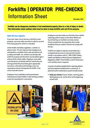
Machine Controls123456ART 2811CONTROLDESCRIPTION1 Lift/Lower SwitchUse to control the lift and lowering of the platform from the base panel, when“BASE” position is selected as the primary control station.2 Base/Off/PlatformSelect “BASE” position to control operation of machine using the basecontrols. Select “PLATFORM” position to control operation of machine usingthe platform console.Selector SwitchNOTE: A key shall be provided for European machines and will be removable in “PLATFORM” position only.3 Emergency StopButtonUse to stop all functions in an emergency. Push for emergency stop.To reset turn clockwise.4 Circuit-breakerPops out when there is excessive electrical load in the 12-volt control circuit.Push in to reset.5 Battery GaugeIndicates percent of charge left in batteries.(Optional)6 Hour MeterIndicates total elapsed time the machine has been operated.Operator's Manual - 2591RT 3391RT 4191RT: CE ModelsPage 6September 2008
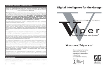
Machine Controls45216738ART 2812CONTROL1 CRIPTIONWith enable bar pressed, controls forward and reverse machine travel atspeed proportional to handle movement.With enable bar pressed, moving controller handle toward the operator(up) will provide platform lift at a speed proportional to handle movement.Moving the handle away from the operator (down) will provide platformlowering at a fixed speed.2 “Left/Right”Push Steer Rocker Switch (thumb) to the left and hold to turn steer wheels tothe left, right to turn steer wheels to the right.3 Enable BarMust be depressed to active drive, steer, and lift functions.4 Mode SelectorDesired selection will allow either the lift or drive function using controllerhandle.5 Emergency StopPush to stop all functions in emergency. Reset by turning clockwise.Button6 Torque On/OffSwitch“ON” selection will provide extra driving torque and reduce drive speed whenthe platform is under approximately 7 ft (2.13 m). “OFF” position is the normalmode.7 Tilt Warning LightIndicates that machine is not level.8 Horn (Optional)Press button to sound warning horn.September 2008Operator's Manual - 2591RT 3391RT 4191RT: CE ModelsPage 7
SAFETYFailure to read, understand, and follow all safety rules, warnings, and instructions willunnecessarily expose you and others to dangerous situations. For your safety and thesafety of those around you, you must operate your machine as instructed in this manual.You, the operator, are the single most important factor for safety when using any pieceof equipment. Learn to operate your machine in a safe manner.To help you recognize important safety information, we have identified warnings andinstructions that directly impact on safety with the following signals:Indicates an imminently hazardous situation which, if not avoided, will result in death orserious injury. This signal word is limited to the most extreme situations.Indicates a potentially hazardous situation which, if not avoided, could result in death orserious injury.Indicates a potentially hazardous situation which, if not avoided, may result in minor ormoderate injury. It may also be used to alert against unsafe practices.Indicates a situation which, if not avoided, may result in damage to the equipment.Safety Rules And PrecautionsMEC designs self-propelled scissor lifts to be safe and reliable. They are intended toposition personnel, along with their necessary tools and materials to overhead worklocations.The owner/user/operator of the machine should not accept responsibility for the operation of the machine, unless properly trained.TIPOVER HAZARDSDO NOT DRIVE NEARDROP-OFFS, HOLESOPEN ELEVATOR SHAFTS,AND LOADING DOCKS.DO NOT ELEVATE PLATFORM ONDO NOT RAISE PLATFORMUNEVEN OR SOFT SURFACESON SLOPE, OR DRIVEDO NOT DRIVE ONTO UNEVEN OR ONTO SLOPE WHEN ELEVATED.SOFT SURFACES WHEN ELEVATED.DO NOT RAISEPLATFORM INWINDY OR GUSTYCONDITIONS.ART 2349Operator's Manual - 2591RT 3391RT 4191RT: CE ModelsPage 8September 2008
Only authorized, trained and qualified personnel should operate the scissor lift. NEVER fasten fall protection lanyard to an adjacent structure while on the platform. Make sure that the platform entry is properly closed and secure before operating machine from the platform. NEVER exceed platform rated capacity. Review the section titled “Machine Specifications” (earlier in this manual) regarding model capacities and dimensions.Before operating the machine, read and understand all safety and control information found on the machine and inthis manual.When operating the machine follow all safety and control information found on the machine and in this manual.Evenly distribute loads placed on the platform.NEVER use scaffolding, ladders or similar items to extend your reach while on the platform.NEVER climb down the beam assembly while the platform is raised.The “Moving the Machine” section (described later in this manual) requires that the brake be released. Afterperforming this procedure, there is no means to stop the machine’s travel. MEC recommends using this procedureonly in cases of emergency, and only for a short distance. Be on guard against machine runaway on slopingsurfaces. Movement speed shall not exceed 5 MPH (8.0 kph).NEVER attempt to open any hydraulic line or component without first relieving all system pressure.NEVER alter, modify, or disable any safety devices or interlocks.NEVER recharge the battery near sparks or open flames. Lead-acid batteries generate EXPLOSIVE HYDROGENGAS. Always wear safety glasses.NEVER use the machine outdoors during electrical storms or in high wind situations.Only raise the platform when the machine is on a firm, level surface.f the Tilt Alarm sounds, use extreme caution and lower the platform. Reposition machine on a firm, level surfacebefore elevating againSECURE all tools and other loose items to prevent injury to persons working on or below the platform.Precautions should be taken to prevent unauthorized personnel from operating the platform with the groundcontrols while the platform is in use. Unassisted loading or unloading of scissorlift from a truck or trailer is not recommended. Before disengaging brakes or disconnecting from a tow vehicle, ensure that the machine cannot roll. NEVER operate this machine outdoors in windy conditions, except model 2047ES. ALWAYS observe the maximum wind speed of 0 m/s, except model 2047ES. Precautions should be taken when operating the machine outdoors. When elevated, pay attention to conditions especially when passing buildings or other large objects that may obscure windy conditions.NEVER modify or alter the machine without prior written permission from the manufacturer.NEVER replace components critical to machine stability with items of different weight or specification. See Serviceand Parts Manual for appropriate replacement part numbers.Do not use batteries that weigh less than original equipment. Each battery must weigh at least 27.3 kg.Complete the “Operational Checklist” at designated intervals.September 2008Operator's Manual - 2591RT 3391RT 4191RT: CE ModelsPage 9
Use of the machine as a crane to lift oversized or hanging loads is prohibited.ALWAYS ensure that the route and areas are clear before driving, lifting or lowering.It is recommended to avoid sudden braking or steering. Go slowly and leave more maneuvering room during cold weather operation.Only lower the outriggers when the machine is on a firm, level surface. The surface must be capable of supporting themaximum ground pressure per wheel/outrigger (see specifications). DO NOT raise the platform unless all four outriggers are properly lowered and the machine is level. DO NOT adjust outriggers while platform is raised. DO NOT drive while outriggers are lowered.Fall Protection NoticeLanyard anchorage pointsare recommended for workpositioning restraints only.Use of fall arrest systemsattached to anchorage pointson mobile equipment maycause machine to tip,resulting in serious injury ordeath.The Guardrail System around the perimeter of the platform is thefall protection system for self-propelled elevating work platforms. Itis prohibited to use an Aerial Work Platform manufactured by MECwith any portion, or all, of the guardrails removed. ELECTROCUTION HAZARD!!! THIS MACHINE IS NOT INSULATED!! Maintain safe clearance from electrically charged conductors (power lines) and apparatus. You must allow formachine sway (side to side movement) when elevated and electrical line movement. This machine does notprovide protection from contact with, or proximity to, an electrically charged conductor. You must maintain a CLEARANCE OF AT LEAST 10 FEET (3.05 m) between any part of the machine, or its load, andany electrical line or apparatus carrying over 300 Volts up to 50,000 Volts. One foot (30.5 cm) additional clearanceis required for every additional 30,000 Volts. DEATH OR SERIOUS INJURY will result from contact with or inadequate clearance from any electrically chargedconductor. Observe Minimum Safe Approach Distance as illustrated on next page. Only authorized, trained and qualified personnel should operate the scissor lift. NEVER fasten fall protection lanyard to an adjacent structure while on the platform. Make sure that the platform entry is properly closed and secure before operating machine from the platform. NEVER exceed platform rated capacity. Review the section titled “Machine Specifications” (earlier in this manual)regarding model capacities and dimensions.Operator's Manual - 2591RT 3391RT 4191RT: CE ModelsPage 10September 2008
M.S.A.D. MINIMUM SAFE APPROACH DISTANCEDENOTES PROHIBITED ZONEDANGER:DO NOT ALLOW MACHINE, PERSONNEL OR CONDUCTIVE MATERIALSINSIDE PROHIBITED ZONE.MAINTAIN M.S.A.D. FROM ALL ENERGIZED LINES AND PARTS AS WELLAS THOSE SHOWN.ASSUME ALL ELECTRICAL PARTS AND WIRES ARE ENERGIZEDUNLESS KNOWN OTHERWISE.CAUTION:DIAGRAMS SHOWN ARE ONLY FOR PURPOSES OF ILLUSTRATINGM.S.A.D. WORK POSITIONS, NOT ALL WORK POSITIONS.MINIMUM SAFE APPROACH DISTANCE (M.S.A.D.)to energized (exposed or insulated) power lines and parts.VOLTAGE RANGE(Phase to Phase)MINIMUM SAFE APPROACH DISTANCE(Feet)(Meters)0 to 300VOver 300V to 50KVOver 50KV to 200KVOver 200KV to 350KVOver 350KV to 500KVOver 500KV to 750KVOver 750KV to 1000KVAVOID CONTACT103.05154.60206.10257.623510.674513.72ART 2351September 2008Operator's Manual - 2591RT 3391RT 4191RT: CE ModelsPage 11
Safety and Instructional Decals1628735498910911101191415171513MECWIND1775 AERIALPARK PLATFORMSELMA,STREET,CA,SPEED0 m/s12.5m/sMAX.ALLOWAINCLINABLEX.X TIONx X.X USASALESSUITE77 CORP.MAX.PLATFOMFG.XXXRMDATEkgXX/XXCAPACITMODELXXX X PERSONkgY INCLUDINUMBER XPERSONS XXXXXXXXXNGkgPERSONSERIALS ICALXXX EQUIPM100-220 .GROUNDNREXXXPLATFOPERNX.XWHEELRMkg/cm²X.X HEIGHTMAX.mPER LOADX.XWHEELmXXXELECTRkgMACHINEXXXX WEIGHTkg12909821815ART 2813Operator's Manual - 2591RT 3391RT 4191RT: CE ModelsPage 1214September 200816
Safety and Instructional Decals12390901907299090145678WARNINGDO NOT POWERWASH ORSPRAY ELECTRONICCOMPONENTS ORCONNECTORS.MOISTURE MAY CAUSEDAMAGE AND/ORERRATIC 7EUR1314MEC AERIAL PLATFORM SALES CORP.1775 PARK STREET, SUITE 77SELMA, CA, USAHYDRAULIC OIL6873WIND SPEED6873MAX. PLATFORM CAPACITY INCLUDING PERSONSSERIAL NUMBERXXXXXXXXXMAX. ALLOWABLEMANUAL FORCEMODEL YEAR20XXMAX.PLATFORM HEIGHT0 m/sXXX kg X PERSONS XXX kg EQUIPMENTXXX NX.X m12.5 m/sXXX kg X PERSONS XXX kg EQUIPMENTXXX NX.X mMAX. ALLOWABLEINCLINATION90267MFG. DATE MODEL NUMBERXX/XXXXXXXXX.X x X.X ELECTRICAL VOLTAGE100-220 VAC50/60 HzMAX. GROUNDPRESSURE PER WHEELX.X kg/cm²MAX. LOADPER WHEELMACHINE WEIGHTXXX kgXXXX kg9098290982161517189093090933 - 453 kg90902 - 485 kg90931 - 628 kg90932 - 701 kg90974 - 776 kg90975 - 875 kg90976 - 910 47ES)(2047ES)9108490918(except 3247ES)(only 3247ES)NOTE: Decals may vary according to countryART 2814September 2008Operator's Manual - 2591RT 3391RT 4191RT: CE ModelsPage 13
OPERATIONDo not operate the machineif tests reveal a defect.Before use each day or at the beginning of each shift, a visualinspection and functional test shall be performed. Repairs must bemade prior to operating the machine to ensure safe operation.Prestart Perform Prestart Inspection (see page 28). Ensure that EMERGENCY STOP switch on the lower controlpanel is reset. Reset the switch by turning it clockwise.ART 2506 Ensure that EMERGENCY STOP switch on the upper controls is reset. Reset the switch by turning it clockwise.ART 2507 Ensure that the battery disconnect switch is in the ON position. Located in control module, to the left of control panel.ART 2356Operator's Manual - 2591RT 3391RT 4191RT: CE ModelsPage 14September 2008
Lower Control Operation And ChecksDO NOT ELEVATE THEPLATFORM IF THEMACHINE IS NOT ON AFIRM LEVEL SURFACEImportant: BE SURE the area above the machine is clear ofobstructions to allow full elevation of platform.DO NOT OPERATE the machine if tests reveal adefect.ELECTROCUTION HAZARD: observe safetyrules outlined on pages 10-11.Emergency StopART 2506Press the EMERGENCY STOP switch at any time to stop all functions. Reset the switch by turning it clockwise.Elevate PlatformOFFART 27421. Turn the base/platform select switch to BASE.2. Activate the Lift/ Lower switch on the base control panel toelevate the platform to the end of its movement. Releasing theswitch should stop elevation.Test Operation Elevate to maximum height. Releasing the button will stop elevation. Pressing the EMERGENCY STOP switch will stop elevation.Lower PlatformART 28151. Activate the Lift/ Lower switch on the base control panel tolower the platform. Release when the desired platform height isreached.2. At approximately 2.5 meter platform height the automaticarmguard cutout will stop the platform. Verify that there are nohazardous conditions and that no other persons are touchingthe machine. After a five second delay lowering can resume.Test Operation Lower the platform to the stowed position. Releasing the button will stop descent. Pressing the EMERGENCY STOP switch will stop descent.Inspection Check for proper operation and hydraulic leaks. Set the maintenance lock before inspecting any items insideor around the scissor arms. Lower the platform to the stowed position.September 2008Operator's Manual - 2591RT 3391RT 4191RT: CE ModelsPage 15
Upper Control Operation and ChecksActivation of the platform“Emergency Stop” button willapply brakes immediately.This may cause unexpectedplatform movement as themachine comes to a suddenstop. Brace yourself andsecure objects on theplatform during operation ofmachine.Check that the route of travel to be taken is clear of persons, obstructions, debris, holes, and drop offs, and is capable of supportingthe machine.1. Turn the base/platform select switch to PLATFORM.2. Enter platform and close and secure the entry.3. Press the horn button on the upper controls to verify properoperation.Emergency Stop (Platform)Press the EMERGENCY STOP switch at any time to stop all functions. Reset the switch by turning it clockwise.ART 2507SteerProportionalJoystickForwardLowerJoystick OperationReverseLiftFunction speed is proportional and is controlled by the movement ofthe joystick. The further it is moved the faster the speed will be. Thejoystick returns to the neutral (center) position when released.IMPORTANT: The Enable Bar must be activated to operate thecontroller for Drive, Steer, and Lift/ LowerFunction.EnableBarART 2363Operator's Manual - 2591RT 3391RT 4191RT: CE ModelsPage 16September 2008
Elevate PlatformART 2512Do Not elevate platformunless guardrails areinstalled and secure.1. Place the MODE SELECT switch in the LIFT position.2. Squeeze the enable bar and move the joystick toward you.Test Operation Rate of lift is proportional and is dependent on the movementof the joystick. Elevate to maximum height. Release the joystick and/or enable bar, or move the joystickto the neutral (center) position to stop elevation. Pressing the EMERGENCY STOP switch will stop elevation. At approximately 2.5 meter platform height the automaticarmguard cutout will stop the platform. Verify that there areno hazardous conditions and that no other persons aretouching the machine. After a five second delay lowering canresume.Lower PlatformIf the roll-out deck isextended check forclearance under deck areabefore lowering platform.1. Place the MODE SELECT switch in the LIFT position.2. Move the joystick away from you.Test Operation Rate of descent is fixed - platform lowers at same rate regardless of handle position. Release the joystick or move it to the neutral (center) positionto stop descent. Pressing the EMERGENCY STOP switch will stop descent.If platform should fail to lowerdo not attempt to climb downthe scissor assembly.Serious injury may result.September 2008Operator's Manual - 2591RT 3391RT 4191RT: CE ModelsPage 17
iftEnableBarIMPORTANT: Always check front steer wheel directionbefore driving.1. Place the MODE SELECT switch in the DRIVE position.2. Squeeze the enable bar and press the steering switch withyour thumb to steer left or right. Release the enable bar or steering switch to stop steering. The wheels will not center themselves after a turn. Theymust be returned to the straight-ahead position with thesteering switch.ART 2363Drive ForwardART 25131. Place the MODE SELECT switch in the DRIVE position.2. Squeeze the enable bar and move the joystick away from you. Drive speed is proportional and is dependent on the movement of the joystick. Release the enable bar or return the joystick to the centerposition to stop. Pressing the EMERGENCY STOP switch will stop drive.Drive ReverseCheck that the route of travelis clear of persons,obstructions, debris, holes,and drop offs, and is capableof supporting the machine.1. Place the MODE SELECT switch in the DRIVE position.2. Squeeze the enable bar and move the joystick toward you. Drive speed is proportional and is dependent on the movement of the joystick. Release the enable bar or return the joystick to the centerposition to stop. Pressing the EMERGENCY STOP switch will stop drive.BrakeFor parking, the brake is automatically applied when the joystick isin the neutral (center) position.Platform Overload IndicatorART 2519The Platform Overload Indicator will light and the platform will notlift when the sensor detects too much weight in the platform. Referto the platform capacity label and adjust the platform load accordingly.Operator's Manual - 2591RT 3391RT 4191RT: CE ModelsPage 18September 2008
Extending the Roll-out Extension DeckIf the roll-out deck isextended check forclearance under deck areabefore lowering platform.The deck will extend in intervals of 6 inches (15 cm) throughout theentire length of the roll-out extension deck. There are two (2)handles that hang from the top rail at the end of the extension deck.Both handles are used to push or pull the extension deck to thedesired position. The right-side handle is attached by cable to aspring-loaded pin at the deck. Lift the right-side handle to raise the spring-loaded pin fromthe locked position. With right-side handle raised, lift the left-side handle andpush to extend or pull to retract the deck. Lower the right-side handle enough for the spring-loaded pinto engage and continue to push or pull until the pin locks intoposition.Lower The Platform RailingNOTE: Optional on 1532ES and 1932ES.Do Not elevate platformunless guardrails areinstalled and secure.September 2008 Place the platform control console on the platform floor. Remove pins from rear railing. Lift rail and pivot forward andplace on platform floor. Remove safety snap pins from extension side rails. Rotaterails down. Remove safety snap pins from front panel and fold rail down. Remove safety snap pins from main platform side rails andfold rails down. To return the machine to normal operation mode position/install all railings securely. Position platform control console.Operator's Manual - 2591RT 3391RT 4191RT: CE ModelsPage 19
Set Maintenance LockSet the maintenance lock before inspecting any items inside oraround scissor beams, or beneath the platform. Elevate the platform about halfway. Rotate the maintenance lock into position. Lower platform until the scissor assembly is supported by themaintenance lock.Maintenance Lock: 1532ES - 1932ES & 2033ES - 2633ESART 2152Maintenance Lock: 2047ES - 2647ES - 3247ESART 2157
Select “PLATFORM” position to control operation of machine using the platform console. NOTE: A key shall be provided for European machines and will be remov-able in “PLATFORM” position only. 3 Emergency Stop Use to sto