Transcription
gGER-4212GE Power SystemsGE Generator Rotor Design,Operational Issues,and Refurbishment OptionsRonald J. ZawoyskyKarl C. TornroosGE Power SystemsSchenectady, NY
GE Generator Rotor Design, Operational Issues, and Refurbishment OptionsContentsOverview . . . . . . . . . . . . . . . . . . . . . . . . . . . . . . . . . . . . . . . . . . . . . . . . . . . . . . . . . . . . . . . . . . . .1Function of a Generator Rotor . . . . . . . . . . . . . . . . . . . . . . . . . . . . . . . . . . . . . . . . . . . . . . . . . .1Types of Generator Rotors . . . . . . . . . . . . . . . . . . . . . . . . . . . . . . . . . . . . . . . . . . . . . . . . . . . . .4Conventional Windings . . . . . . . . . . . . . . . . . . . . . . . . . . . . . . . . . . . . . . . . . . . . . . . . . . . . . .4Generator Rotors with Aluminum Alloy Windings . . . . . . . . . . . . . . . . . . . . . . . . . . . . . . . . . .5Direct-Cooled Windings . . . . . . . . . . . . . . . . . . . . . . . . . . . . . . . . . . . . . . . . . . . . . . . . . . . . .5Radial Flow Cooling . . . . . . . . . . . . . . . . . . . . . . . . . . . . . . . . . . . . . . . . . . . . . . . . . . . . . . . . .5Radial-Axial-Radial Cooling . . . . . . . . . . . . . . . . . . . . . . . . . . . . . . . . . . . . . . . . . . . . . . . . . . .6Diagonal Flow Cooling . . . . . . . . . . . . . . . . . . . . . . . . . . . . . . . . . . . . . . . . . . . . . . . . . . . . . . .7Laminated Rotors . . . . . . . . . . . . . . . . . . . . . . . . . . . . . . . . . . . . . . . . . . . . . . . . . . . . . . . . . .7Current 4-Pole Salient Pole Rotors . . . . . . . . . . . . . . . . . . . . . . . . . . . . . . . . . . . . . . . . . . . . . .8Problems Encountered with Generator Rotors . . . . . . . . . . . . . . . . . . . . . . . . . . . . . . . . . . . . .8Shorted Turns and Field Grounds . . . . . . . . . . . . . . . . . . . . . . . . . . . . . . . . . . . . . . . . . . . . . . .8Thermal Sensitivity . . . . . . . . . . . . . . . . . . . . . . . . . . . . . . . . . . . . . . . . . . . . . . . . . . . . . . . .10Contamination . . . . . . . . . . . . . . . . . . . . . . . . . . . . . . . . . . . . . . . . . . . . . . . . . . . . . . . . . . . .11Collector, Bore Copper and Connection Problems . . . . . . . . . . . . . . . . . . . . . . . . . . . . . . . . . .12Copper Distortion . . . . . . . . . . . . . . . . . . . . . . . . . . . . . . . . . . . . . . . . . . . . . . . . . . . . . . . . . .12Forging Concerns . . . . . . . . . . . . . . . . . . . . . . . . . . . . . . . . . . . . . . . . . . . . . . . . . . . . . . . . . .12Retaining Ring Concerns . . . . . . . . . . . . . . . . . . . . . . . . . . . . . . . . . . . . . . . . . . . . . . . . . . . .13Misoperation . . . . . . . . . . . . . . . . . . . . . . . . . . . . . . . . . . . . . . . . . . . . . . . . . . . . . . . . . . . . .15Generator Rotor Reliability and Life Expectancy . . . . . . . . . . . . . . . . . . . . . . . . . . . . . . . . . .15Generator Rotor Life . . . . . . . . . . . . . . . . . . . . . . . . . . . . . . . . . . . . . . . . . . . . . . . . . . . . . . .15Generator Experience . . . . . . . . . . . . . . . . . . . . . . . . . . . . . . . . . . . . . . . . . . . . . . . . . . . . . .16Generator Rotor Refurbishment and Replacement . . . . . . . . . . . . . . . . . . . . . . . . . . . . . . . .16Generator Rotor Rewind . . . . . . . . . . . . . . . . . . . . . . . . . . . . . . . . . . . . . . . . . . . . . . . . . . . .16Reasons for Rewinding . . . . . . . . . . . . . . . . . . . . . . . . . . . . . . . . . . . . . . . . . . . . . . . . . .16Types of Insulation . . . . . . . . . . . . . . . . . . . . . . . . . . . . . . . . . . . . . . . . . . . . . . . . . . . . . .17Generator Rotor Modifications, Upgrades and Uprates . . . . . . . . . . . . . . . . . . . . . . . . . . . . .18Impact on Other Components . . . . . . . . . . . . . . . . . . . . . . . . . . . . . . . . . . . . . . . . . . . . . .19Generator Rotor Replacement . . . . . . . . . . . . . . . . . . . . . . . . . . . . . . . . . . . . . . . . . . . . .20Exchange Field . . . . . . . . . . . . . . . . . . . . . . . . . . . . . . . . . . . . . . . . . . . . . . . . . . . . . . . . .20New Field . . . . . . . . . . . . . . . . . . . . . . . . . . . . . . . . . . . . . . . . . . . . . . . . . . . . . . . . . . . . .20GE Power Systems GER-4212 (08/01) i
GE Generator Rotor Design, Operational Issues, and Refurbishment OptionsRewind, Refurbishment and Replacement Recommendations Versus Risk . . . . . . . . . . . . . . .20New Replacement Rotor . . . . . . . . . . . . . . . . . . . . . . . . . . . . . . . . . . . . . . . . . . . . . . . . .20Exchange Field . . . . . . . . . . . . . . . . . . . . . . . . . . . . . . . . . . . . . . . . . . . . . . . . . . . . . . . . .20Rewind with New Copper . . . . . . . . . . . . . . . . . . . . . . . . . . . . . . . . . . . . . . . . . . . . . . . .21Rewind Reusing Old Copper . . . . . . . . . . . . . . . . . . . . . . . . . . . . . . . . . . . . . . . . . . . . . . .21High Speed Balancing . . . . . . . . . . . . . . . . . . . . . . . . . . . . . . . . . . . . . . . . . . . . . . . . . . . . . . . .21High Speed Balance . . . . . . . . . . . . . . . . . . . . . . . . . . . . . . . . . . . . . . . . . . . . . . . . . . . . . . .21Flux Probe Test . . . . . . . . . . . . . . . . . . . . . . . . . . . . . . . . . . . . . . . . . . . . . . . . . . . . . . . . . . .21Thermal Sensitivity Test . . . . . . . . . . . . . . . . . . . . . . . . . . . . . . . . . . . . . . . . . . . . . . . . . . . .22Conclusion . . . . . . . . . . . . . . . . . . . . . . . . . . . . . . . . . . . . . . . . . . . . . . . . . . . . . . . . . . . . . . . . .22Frequently Asked Questions . . . . . . . . . . . . . . . . . . . . . . . . . . . . . . . . . . . . . . . . . . . . . . . . . . .22List of Figures . . . . . . . . . . . . . . . . . . . . . . . . . . . . . . . . . . . . . . . . . . . . . . . . . . . . . . . . . . . . . . .24List of Tables . . . . . . . . . . . . . . . . . . . . . . . . . . . . . . . . . . . . . . . . . . . . . . . . . . . . . . . . . . . . . . . .24GE Power Systems GER-4212 (08/01) ii
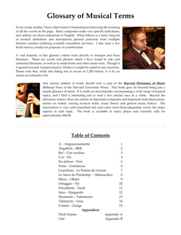
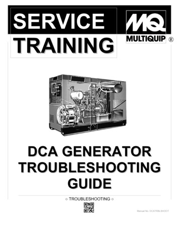
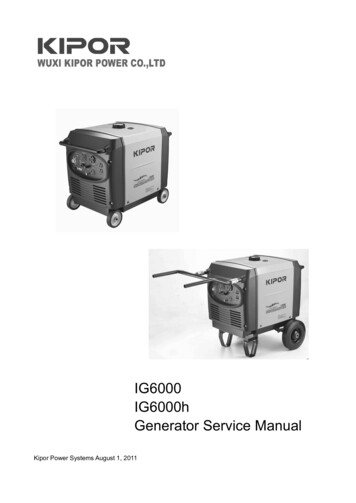
GE Generator Rotor Design, Operational Issues, and Refurbishment OptionsOverviewWith the average age of the GE generator fleetrapidly approaching the limit of the originalintended life, utilities and industrial users areseeking alternatives to replace this aging equipment with new generators. One component ofthe generator that is typically refurbished,upgraded or uprated is the generator rotor(field). Degradation of the generator field canbe caused by a number of factors, including abreakdown in insulation due to time and temperature and mechanical wear. This degradation can lead to shorted turns, a field ground,or an in-service operational incident that canrequire premature maintenance work. The typeof work needed to repair and upgrade dependsupon the generator rotor design, length of timein service and the manner in which the rotorwas operated.This paper covers various types of generatorfields, including both conventionally-cooled(indirect copper cooling) windings and directcooled copper windings as well as those withspindle and body mounted retaining rings. Theoptions for rewinding, modifying, upgrading oruprating are provided for each field type. Alsoaddressed in this text are the problems typicallyencountered when dealing with generatorrotors, including:rotor reliability and its life expectancy—whichvaries considerably based on the type and configuration of the generator rotor and the manner in which it is operated.Function of a Generator RotorThis section covers the generator field’s function in two main areas: a brief description of themechanical configurations, and a brief description of the electrical theory.The generator rotor represents an excellentcombination of electrical, mechanical and manufacturing skills in which the field coils are wellinsulated, supported and ventilated in a compound structure rotating at very high speed(typically 1800 or 3600 rpm). Furthermore,though the rotor experiences great mechanicalstress and high temperatures (in some cases upto 266 F–311 F/130 C–155 C) while subjectedto electrical voltage and current, it is expectedto function in this manner for years without failure. The three design constraints that limitthe size and life of generator rotors are temperature, mechanical force and electrical insulation.Figure 1 shows a basic mechanical outline for atypical generator field. Note the major components: Shorted turns Turbine coupling Field grounds Main cooling fans Thermal sensitivity Retaining rings Negative sequence heating Coil slot Contamination Balance plug Misoperation Collector rings Forging damage Collector fansThe issue of balancing generator rotors afterrework or modifications is also discussed. Thispaper concludes with a discussion on generatorGE Power Systems GER-4212 (08/01) There are, of course, variations on this configuration. For example, while the illustrated designuses radial fans, other designs use axial fans.1
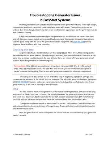
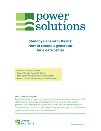
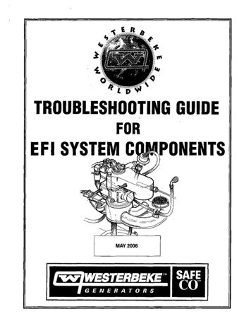
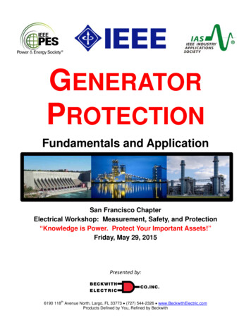
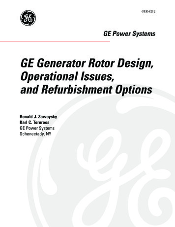
GE Generator Rotor Design, Operational Issues, and Refurbishment OptionsFANCOIL OLLECTORFANFigure 1. Generator fieldA typical collecter end configuration is shown inFigure 2, which also shows a cutaway view of vitalelectrical components such as: Collectors Collector terminalsFigure 3 shows a typical cross-section of a radialcooled slot section. Other configurations will bedescribed later. Note the main components ofthe slot: Coil wedge Bore copper Creepage block Main terminal Slot armor Main lead Turn insulation (groundwall insulation) Retaining ring Coil endwindings (shown from the side) Copper turns Axial fan Subslot coverFIELD COIL ENDWINDINGSRETAININGRINGAXIAL FANMAINTERMINALCOLLECTORSMAIN LEADSBORE COPPERCOLLECTOR TERMINALFigure 2. Collector end of generator fieldGE Power Systems GER-4212 (08/01) 2
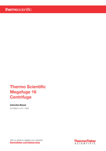
GE Generator Rotor Design, Operational Issues, and Refurbishment OptionsCOIL WEDGEROTORCREEPAGEBLOCKSLOT WIDTH)SUB SLOTCOVERSLOTCLEARANCE(RADIAL)SUB SLOTFigure 3. Radial cooled slotTo understand the intricacies of the field winding design, it must be remembered that thebasic function of the rotor is to produce a magnetic field of the size and shape necessary toinduce the desired output voltage in the stator.The rotor can be visualized as a large rotatingelectromagnet with north and south poles. Asillustrated in Figure 4, the magnetic flux thatradiates from the rotor follows the magnetic cir-cuit across the air gap, through the stator coreand then back across the air gap into the rotorto complete the loop.Simply stated, the primary function of the fieldwinding is to provide the path for the DC currentneeded to magnetize the field. However, reaching this goal is not so simple. It involves manytradeoffs in trying to satisfy all the mechanical,electrical, thermal, and manufacturing constraints. Consider just this basic list of requirements for the field winding and its components: The winding and associated components must withstand centrifugal loading at speed and possible overspeed. The winding and its insulation systemmust fit within the space available forthe rotor slot. The amount of spaceavailable for the rotor slot is dependent on the stresses in the rotor teeth—the more area used for the slot, thehigher the tooth stresses. The insulation system must be sufficient to protect the winding fromground faults and turn-to-turn shortsthroughout the operating envelope.AIR GAPGENERATORFIELDSTATORFigure 4. Rotor magnetic flux linking rotor and statorGE Power Systems GER-4212 (08/01) 3
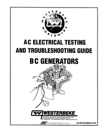
GE Generator Rotor Design, Operational Issues, and Refurbishment Options The insulation system must be strongenough to withstand the physical wearand tear of assembly and winding, andduring operation (particularly when inthe turning gear mode). The ventilation scheme must be sufficient to keep the temperature rises ofthe winding within the acceptablerange. In the case of ventilated endwindings the vent paths must be optimized to provide sufficient coolingwhile not exceeding the stress limits ofthe copper. The field MMF (magnetomotive force)must be sinusoidal in shape and of thedesired magnitude. The winding must be symmetrical andbalanced to prevent unacceptablevibrations.The winding and components should bedesigned to require little maintenance duringthe 30 or more years of expected operation,which is the typical life for a base loaded controlpower station. Rewinds may be more frequentunder extreme conditions such as an open ven-tilated gas turbine generator in a dirty environment, or frequent start/stops or load cycling.Types of Generator RotorsThere are two basic types of generator rotors:conventional windings (indirect-cooled) anddirect windings (conductor-cooled). Both typesand their variations are discussed.Conventional WindingsSmaller generators, which are not providedwith conductor cooling, have ventilating ductsthrough which the cooling air passes. (SeeFigure 5.) With this arrangement, the heat generated in the coil is conducted through the slotinsulation to the field forging, then to the cooling gas in the ventilating duct. The dielectricbarrier forming the slot insulation is also theprimary thermal barrier in the circuit; as current levels increase, additional rotor heat dissipation is required. The solution is to use a conductor-cooling arrangement, in which coolinggas flows directly through the conductors. Thiseliminates the thermal barrier of the slot insulation, allowing a continued increase in the current-carrying capability of a given size LATINGDUCTCOPPERWINDINGSLOTINSULATIONFigure 5. Indirect cooled coil slotGE Power Systems GER-4212 (08/01) 4
GE Generator Rotor Design, Operational Issues, and Refurbishment OptionsGenerator Rotors with Aluminum AlloyWindingsWEDGEAs conventionally cooled generators wereincreased to larger sizes, the generator rotorstresses increased to unacceptable levels in therotor and retaining rings. Aluminum alloy (condal) windings were incorporated on some generator rotors, enabling the rotor size and ratings to increase and still allow conventionalindirect cooling to be used in the design ofthese units. These units have provided manyyears of reliable operation. However, to ensurefuture long-term reliability when they arerebuilt, the design of these units requires special design and process LATIONCOPPERWINDINGDirect-Cooled WindingsSUB SLOTSeveral different arrangements of direct-cooledwindings have been used by domestic and foreign manufacturers to accomplish the conductor-cooling principle. The two primary methodscurrently used by GE for two-pole generatorsare radial flow cooling and diagonal flowcooling, as shown respectively in Figure 6 andFigure 7.Figure 6. Radial cooled coil slotROTATIONRadial Flow CoolingRadial flow cooling is used for small and medium sized two-pole units and for large four-poleunits. The ventilation arrangement shown inthe slot cross-section of Figure 6 permits gas toenter the subslot in an axial direction. The gasthen discharges radially through holes in thecopper winding and through the wedges shownin the figure. This conductor cooling arrangement brings the cooling gas into direct contactwith the copper conductors, eliminating thethermal drop through the insulation. Thewedges are constructed with pre-drilled holes toallow for the passage of gas to the rotor surface.GE Power Systems GER-4212 (08/01) NSULATIONSTRIPEXTRUDEDCOPPERCHANNELFigure 7. Diagonal cooled coil slot5
GE Generator Rotor Design, Operational Issues, and Refurbishment Optionstors, and then to air-cooled generators. This isjust one example of the development of technology for large generators that is then utilizedto enhance smaller units.The rotor slot in Figure 6 may be tapered to provide an optimum balance between total copperarea and rotor forging stresses. The size andcontour of the subslot, along with the size andnumber of radial holes in the copper andwedges, are parameters designed specifically tokeep the copper and insulation temperaturesand rotor forging stresses within standard andmaterial limits.Radial-Axial-Radial CoolingFour-pole rotor windings are subject to muchless duty than those with two-pole designs. Thefour-pole rotor turns at half the speed, so thecentrifugal loading of the copper windingagainst the wedges and retaining rings is considerably reduced. Much larger diameters ofthe large four-pole generators permit use ofdeeper and wider slots to accommodate a larger cross-section of copper winding. Increasedrotor diameter also increases the availablepumping head for forced convection cooling.All these factors ease the problem of designingthe rotor cooling circuitThis type of cooling system was GE's first provendesign at gap pickup cooling. (See Figure 8.) Thegenerator rotor and stator incorporated inletand outlet sections along their axial lengthsto achieve uniform cooling along the length ofthe generator field. This uniform cooling eliminated axial hotspots and allowed the ratings ofthe generators to be increased. The design wasnamed radial-axial-radial because of the coolingflow which enters the rotor radially, goes in aradial direction into the winding, then proceedsin an axial direction and finally in a radial direction out of the winding. (See Figure 9.) This cooling scheme is accomplished by using extrudedcopper conductors that have been intricatelymachined to achieve the desired cooling pattern.The radial flow direct-cooling arrangement wasoriginally developed for large hydrogen-cooledfour-pole generators. Once perfected, it wasadapted to two-pole hydrogen cooled genera-This design had been used very successfully andreliably for over 40 years. However, the designwas replaced by diagonal flow design, whichalso incorporated a gap pickup. Diagonal flowOUTLETINOUTINOUTINOUTINOUTCOREFigure 8. Rotor and stator cooling zonesGE Power Systems GER-4212 (08/01) 6
GE Generator Rotor Design, Operational Issues, and Refurbishment OptionsFigure 9. Radial-axial-radial cooled coil slotoffered the additional benefit of a simplerdesign that allowed it to be manufactured moreeasily, while increasing long term reliabilitywithout sacrificing performance. If a radialaxial-radial field requires a rewind, it is typicallyconverted to a diagonal flow design or replacedwith a new diagonal cooled rotor.Diagonal Flow CoolingThe arrangement used in large two-pole generators is referred to as diagonal flow cooling.Figure 7 shows a detailed cross-section of a typical diagonal flow field coil. Gas flows downthrough a series of slotted holes, offset in eachlayer from those in the previous layer. The bottom turn is a channel that redirects the gas toanother series of slotted holes which force thegas upward in a diagonal progression to the topof the coil. The pumping action to provide gasflow is obtained in the configuration of the slotwedges, requiring little fan pressure to circulategas through the rotor winding. The holes forgas inlet are inclined in such a manner thatrotation of the field forces the gas through thewedge and down into successive turns of thecoil. Discharge holes in the wedges have araised section preceding the hole in the direction of rotation. This creates a pressure reduction at the hole with the lower pressure inducing gas flow by suction from the discharge end.There are several alternate inlet and dischargeGE Power Systems GER-4212 (08/01) sections throughout the length of the rotor,providing multiple parallel paths through thewinding (as shown in Figure 8). The stator corehas corresponding inlet and outlet sections,matching those in the generator field.Laminated RotorsUntil 1940 some older, smaller generator rotorswere constructed with laminated steel (e.g., 5MVA in 1935) in limited number. GE occasionally will get a request for spare parts, which wecan generally support. Laminated rotors wereconstructed of a shaft forging and laminatedfull circle punchings shrunk onto the shaft withthe collector end secured by a large nut to keepthe punchings tight. A few of these units experienced vibration problems because the punchings shifted, causing a kink. Finding the kinkedlocation and straightening out the punchingpackage would usually fix the vibration. Theselaminated rotors were built with a stator bore ofup to 23.75 inches. Beyond that, the rotorshould be a solid design. The fields had a oneor two-piece coil slot wedge made of brass, andon some early units the wedges were actuallyinsulated from the rotor laminations. The laminated rotors had radiating plates and sometimes holes in the retaining rings for end turncooling. Generally such a rotor cannot beuprated, mainly due to flux density limitationsof the original design.7
GE Generator Rotor Design, Operational Issues, and Refurbishment OptionsCurrent 4-Pole Salient Pole RotorsGE continues to produce state-of-the-art salientlaminated rotors to support the GE 4-PoleAlterrex Excitation System (typical ratings areup to 4375 KVA). Of course vast improvementshave been made in the design over the past 50years compared to what was discussed in theprevious paragraph. However, the rotors arelimited in diameter and are most appropriatefor machines in the smaller MVA ratings.Problems Encountered With GeneratorRotorsAs a generator rotor ages, its insulation can beaffected by temperature, mechanical wear andoperating incidents. Rotor forging and otherrotor components are also at risk. The mostcommon problems occurring with generatorrotors are shorted turns and breakdown ingroundwall insulation. These two concerns willbe discussed in detail.Shorted Turns and Field GroundsA short or ground occurs when the insulation inthe field is damaged. A short results when theinsulation between the copper turns is alteredlocally, allowing the adjacent turns to make contact. Although this is not desirable, generatorfields have operated—and will operate—with alimited number of shorted turns without significant effect to the operation of the generator.Shorts can occur anywhere in the winding ofthe generator; however, they are most commonin the endwinding area under the retainingrings.Grounds occur because of a breakdown in thegroundwall insulation. This can be in the slotportion of the field, under the retaining ring, atthe main lead and terminals or collector andcollector terminals, or in the bore copperregion. However, unlike having a short, it is rec-GE Power Systems GER-4212 (08/01) ommended not to operate a field with aground. As the source of excitation isungrounded, a single ground will not cause current to circulate in the field forging. Yet if a second ground should occur, current will circulatein the forging, and in a very short period oftime melting and serious damage to the forgingcan result.Figure 10 shows an example of both a short anda ground in the slot section of a generator field.It should be noted that the short only affects theinsulation between the turns of copper windings, while the ground wall insulation is notaffected. Figure 11 is an example of a ground inthe endwinding area between the top turn ofthe winding and the retaining ring.The following conditions can lead to field insulation breakdown: Time. The longer a generator has beenin service, the higher the probabilitythat the soundness of the insulationhas been compromised by mechanicalstress or heat related damage.COIL INDINGWINDINGSHORTTURNINSULATIONSLOTARMORFigure 10. Coil slot insulation breakdown8
GE Generator Rotor Design, Operational Issues, and Refurbishment OptionsRETAINING RINGINSULATIONGROUNDLOCATIONRETAINING RINGEND WINDINGSFigure 11. Field endwinding insulation breakdown Type of operation. A generator fieldthat is subject to many start-stopsand/or VAR cycling is more prone to adegrading of the insulation systemthan a field that is baseloaded. Contamination. The integrity of theinsulation can be jeopardized if contamination has been introduced intothe machine or if there has been anyburning in the generator (which produces conductive material that can circulate inside the generator). This phenomenon is discussed in detail later inthe paper. Operating incidents. Any operatingincidents that induce heating, burning,arcing, high stresses, etc., can be detrimental to the insulation. This abnormal operation includes motoring, anegative sequence event (closing generator breaker at standstill or turninggear or single phase operation), burning within the generator or an overspeed incident.As mentioned previously, in many cases the generator can operate satisfactorily with shortedturns in the field, whereas it is not recommended that a field be operated with a ground. WhileGE Power Systems GER-4212 (08/01) shorts are undesirable, they do not present anysignificant risk to the machine. Consequencesof operating a field with shorts include theinability to reach the nameplate rating on themachine and the possibility of developing athermally sensitive generator field. In the worstcase, this would require a full field rewind inwhich all winding insulation would be replaced.In the case of a single field ground, current willnot flow in the field forging. However, if a second ground occurs, current will immediatelystart to flow between the two ground points.Within a matter of seconds this current couldgenerate enough heat to melt the field forging,wedges or retaining ring. This could causeirreparable damage to the affected components, and in the worst case, result in the rotorbursting.If a field ground occurs, the cause should beimmediately determined and corrective actionshould be taken. Operating with a ground canlead to serious field damage and even to catastrophic failure should a second ground occur.Unfortunately, there is no way to determine ifand when a second ground will occur.As units age and experience many start-stopcycles, the turn insulation will degrade. In suchconditions it is not uncommon for shorted9
GE Generator Rotor Design, Operational Issues, and Refurbishment Optionsturns to develop. Many units have operated foryears with shorted turns without affecting thefunction of the field or the generator. It is onlynecessary to repair the shorted turns when theoperation of the generator is unacceptablyaffected (i.e, the unit rating cannot beobtained, or unacceptable thermal sensitivitydevelops).Regular inspection and testing of the generatorfield is the best way to ensure the integrity of theinsulation system. If an insulation fault develops, a number of diagnostic tests can pinpointthe location and severity of the fault. This ability to quickly and accurately diagnose the problem minimizes the time required to implementcorrective action, allowing the field to bereturned to service in the shortest possibletime.There are a number of other concerns that alsoaffect generator rotors.Thermal SensitivityThermal sensitivity is the term used to describean excessive vibration of the generator rotor,induced by the heating effect of the field current. As field current flows in the winding, thecopper heats up. Two things happen as a consequence:1. The copper, having a greater coefficient ofthermal expansion, expands more than thesteel forging. This disparity in expansionresults in the transmission of forces to theforging through the rotor slots, wedges,retaining ring and centering ring.2. The heat generated in the copper dissipatesinto the forging and is drawn away by thecooling medium (air or hydrogen).As long as both of these conditions occur symmetrically about the rotor centerline, there willbe no forces that tend to "bow" the rotor.GE Power Systems GER-4212 (08/01) However, when the coil forces act unevenly, orwhen a temperature differential exists acrossthe rotor, the rotor will tend to bow, causing animbalance and subsequent vibration.A thermally sensitive field will exhibit a changein vibration magnitude and/or phase anglewith a change in field current. The circumstances that might cause a non-uniform distribution of forces are varied. Some of the morecommon factors that may cause thermal sensitivity (either singularly or in combination)include: Shorted turns. When a significantnumber of adjacent field turns areshorted, the pole with the greaternumber of turn shorts will have a lowerresistance than the other pole. Withthe same current flowing, the higherresistance pole (the one with lessshorts) will heat up and expand morethan the other, causing a bow in itsdirection. Blocked ventilation. A blockedventilation path may cause an unevenheat distribution in the rotor in muchthe same way that shorted turns can. Insulation variation. Non-uniformityin field insulation can result in bindingof the field coils and an unevendistribution of friction forces, both inthe slots and under the retaining ring.In this case, the coils with the greaterbinding or friction will transmit agreater axial load to the rotor, againcausing the rotor to bow. Wedge fit. Uneven tightness of thefield wedges can also result in nonuniform distribution of axial forcesaround the rotor. This situation is mostprevalent when a portion of a field's10
GE Generator Rotor Design, Operational Issues, and Refurbishment Optionswedges are replaced and the fit of thenew wedges is inconsistent with thoseof the existing wedges. Endwinding blocking fit. Similar touneven wedge fits, unevenly spacedand fitted distance blocks can cause anon-uniformity of forces to betransmitted to the rotor, againresulting in bowing of the rotor and achange in its dynamic characteristics.This situation is most common in fieldsha
GE Power Systems GER-4212 (08/01) 2 GE Generator Rotor Design, Operational Issues,