Transcription
ICND1Interconnecting CiscoNetworking Devices,Part 1Volume 2Version 2.0Student GuidePart Number: 97-3243-01
Americas HeadquartersCisco Systems, Inc.San Jose, CAAsia Pacific HeadquartersCisco Systems (USA) Pte. Ltd.SingaporeEurope HeadquartersCisco Systems International BVAmsterdam,The NetherlandsCisco has more than 200 offices worldwide. Addresses, phone numbers, and fax numbers are listed on the Cisco Website atwww.cisco.com/go/offices.Cisco and the Cisco logo are trademarks or registered trademarks of Cisco and/or its affiliates in the U.S. and other countries. Toview a list of Cisco trademarks, go to this URL: www.cisco.com/go/trademarks. Third party trademarks mentioned are the propertyof their respective owners. The use of the word partner does not imply a partnership relationship between Cisco and any othercompany. (1110R)DISCLAIMER WARRANTY: THIS CONTENT IS BEING PROVIDED “AS IS.” CISCO MAKES AND YOU RECEIVE NOWARRANTIES IN CONNECTION WITH THE CONTENT PROVIDED HEREUNDER, EXPRESS, IMPLIED, STATUTORY OR INANY OTHER PROVISION OF THIS CONTENT OR COMMUNICATION BETWEEN CISCO AND YOU. CISCO SPECIFICALLYDISCLAIMS ALL IMPLIED WARRANTIES, INCLUDING WARRANTIES OF MERCHANTABILITY, NON-INFRINGEMENT ANDFITNESS FOR A PARTICULAR PURPOSE, OR ARISING FROM A COURSE OF DEALING, USAGE OR TRADE PRACTICE.This learning product may contain early release content, and while Cisco believes it to be accurate, it falls subject to thedisclaimer above. 2013 Cisco Systems, Inc.
Table of ContentsBuilding a Medium-Sized Network4-1Implementing VLANs and Trunks4-3Issues in a Poorly Designed NetworkVLAN IntroductionTrunking with 802.1QCreating a VLANAssigning a Port to a VLANConfiguring an 802.1Q TrunkVLAN Design ConsiderationsPhysical Redundancy in a LANSummaryRouting Between VLANsPurpose of Inter-VLAN RoutingOptions for Inter-VLAN RoutingConfiguring a Router with a Trunk LinkSummaryUsing a Cisco Network Device as a DHCP ServerNeed for a DHCP ServerUnderstanding DHCPConfiguring a DHCP ServerMonitoring DHCP Server FunctionsDHCP Relay AgentSummaryIntroducing WAN TechnologiesIntroducing WANsWANs vs. LANsRole of Routers in WANsWAN Communication Link OptionsPoint-to-Point ConnectivityConfiguring a Point-to-Point 4-484-504-514-524-534-54Introducing Dynamic Routing Protocols4-55Purpose of Dynamic Routing ProtocolsInterior and Exterior Routing Protocols4-554-58Distance Vector and Link-State Routing ProtocolsUnderstanding Link-State Routing ProtocolsSummary4-594-614-64Implementing OSPF4-65Introducing OSPFOSPF AdjacenciesSPF AlgorithmRouter ID4-654-674-694-71
Configuring Single-Area OSPFVerifying OSPF ConfigurationSummaryModule SummaryModule Self-CheckIntroducing IPv6Introducing Basic IPv6IPv4 Addressing Exhaustion WorkaroundsIPv6 FeaturesIPv6 AddressesIPv6 Unicast AddressesIPv6 Addresses AllocationBasic IPv6 ConnectivitySummaryUnderstanding IPv6IPv6 Header Changes and BenefitsICMPv6Neighbor DiscoveryStateless AutoconfigurationSummaryConfiguring IPv6 RoutingRouting for IPv6Static RoutingOSPFv3SummaryModule SummaryModule Self-CheckGlossaryiiInterconnecting Cisco Networking Devices, Part -41G-1 2013 Cisco Systems, Inc.
Module 4Building a Medium-SizedNetworkWhen you understand how a switch and router operate, how they communicate, and how to configure basicsecurity, you can move on to understanding an expanded network. This module shows how to "virtualize"your LAN using VLANs and how to configure Layer 3 connectivity between these VLANs. Then itdescribes how to decrease the administrative burden of assigning IP addresses by using DHCP. Theintroduction to WANs continues with an explanation of OSPF and of how to configure this routing protocolso that a branch office router can exchange routing information with a headquarters router.ObjectivesUpon completing this module, you will be able to meet these objectives:Implement and verify VLANs and trunkingDescribe the application and configuration of inter-VLAN routingConfigure a Cisco IOS DHCPv4 server on a Cisco router and switchDescribe WANs and list major technologiesDescribe the need for and purpose of dynamic routing protocolsDescribe the operation and configuration of single-area OSPF
4-2Interconnecting Cisco Networking Devices, Part 1 2013 Cisco Systems, Inc.
Lesson 1Implementing VLANs andTrunksVLANs contribute to network performance by separating large broadcast domains into smaller segments. AVLAN allows a network administrator to create logical groups of network devices. These devices act as ifthey were in their own independent network, although they share a common infrastructure with otherVLANs. A VLAN is a logical broadcast domain that can span multiple physical LAN segments. Within theswitched internetwork, VLANs provide segmentation and organizational flexibility. You can design aVLAN structure that lets you group stations that are segmented logically by functions, project teams, andapplications, without regard to the physical location of the users. VLANs allow you to implement accessand security policies to particular groups of users.A VLAN can exist on a single switch or span multiple switches. VLANs can include stations in a singlebuilding or multiple-building infrastructures. VLANs can also connect across WANs. A process offorwarding network traffic from one VLAN to another VLAN using a router is called inter-VLAN routing.VLANs are associated with unique IP subnets on the network. This subnet configuration facilitates therouting process in a multi-VLAN environment. When you use a router to facilitate inter-VLAN routing, therouter interfaces can be connected to separate VLANs. Devices on those VLANs send traffic through therouter to reach other VLANs.When multiple switches are implemented on the same network, there is a potential for intentional orunintentional physical loops. When loops occur, broadcast storms may result, propagating framesthroughout the network. STP solves the problem of broadcast storms by disabling redundant links andkeeping them on standby if the primary link fails.ObjectivesUpon completing this lesson, you will be able to meet these objectives:Describe the issues in poorly designed LANsDescribe the purpose and functions of VLANsDefine the purpose and function of trunking
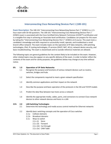
Implement and verify VLANsAssign ports to a VLANConfigure and verify IEEE 802.1Q trunkingDescribe VLAN design and creation guidelinesDescribe how redundancy in a network can cause broadcast loops and describe a solution to thisproblemIssues in a Poorly Designed NetworkThis topic describes the common issues that are found in poorly designed local networks.Issues in a Poorly Designed NetworkThese issues are often found inpoorly designed networks:WANLarge broadcast domainsInternetManagement and supportchallengesPossible security ccountingEngineeringSalesHR 2013 Cisco Systems, Inc.A poorly designed network has increased support costs, reduced service availability, and limited support fornew applications and solutions. Less-than-optimal performance directly affects end users and their access tocentral resources. Some of the issues that stem from a poorly designed network include the following:Large broadcast domains: Broadcasts exist in every network. Many applications and networkoperations use broadcasts to function properly. Therefore, it is not possible to eliminate themcompletely. In the same way that avoiding failure domains involves clearly defining boundaries,broadcast domains should also have clear boundaries. They should also include an optimal number ofdevices to minimize the negative effect of broadcasts.Management and support difficulties: A poorly designed network may be disorganized, poorlydocumented, and lack easily identified traffic flows, all of which can make support, maintenance, andproblem resolution time-consuming and difficult.Possible security vulnerabilities: A switched network that has been designed with little attention tosecurity requirements at the access layer can compromise the integrity of the entire network.Failure domains: One of the reasons to implement an effective network design is to minimize theextent of problems when they occur. When Layer 2 and Layer 3 boundaries are not clearly defined,failure in one network area can have a far-reaching effect.4-4Interconnecting Cisco Networking Devices, Part 1 2013 Cisco Systems, Inc.
A poorly designed network always has a negative effect, and it becomes a support burden and a cost burdenfor any organization. 2013 Cisco Systems, Inc.Student Guide4-5
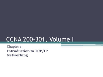
VLAN IntroductionThis topic describes the basic idea behind VLANs.VLAN IntroductionA VLAN is a virtual LAN.VLAN broadcast domainThirdFloorVLAN logical network(subnet)SecondFloorVLANs address these needs:SegmentationSecurityNetwork 2.0/24 10.0.3.0/24 10.0.4.0/24 2013 Cisco Systems, Inc.VLANs improve network performance by separating large broadcast domains into smaller segments. AVLAN allows a network administrator to create logical groups of network devices. These devices act as ifthey were in their own independent network, even if they share a common infrastructure with other VLANs.A VLAN is a logical broadcast domain that can span multiple physical LAN segments. Within the switchedinternetwork, VLANs provide segmentation and organizational flexibility. You can design a VLANstructure that lets you group stations that are segmented logically by functions, project teams, andapplications, without regard to the physical location of the users. VLANs allow you to implement accessand security policies to particular groups of users. You can assign each switch port to only one VLAN,which adds a layer of security (if the port is operating as an access port). Ports in the same VLAN sharebroadcasts. Ports in different VLANs do not share broadcasts. Containing broadcasts within a VLANimproves the overall performance of the network.A VLAN can exist on a single switch or span multiple switches. VLANs can include stations in a singlebuilding or multiple buildings. VLANs can also connect across WANs. The process of forwarding networktraffic from one VLAN to another VLAN using a router is called inter-VLAN routing. VLANs areassociated with unique IP subnets on the network. This subnet configuration facilitates the routing processin a multi-VLAN environment. When you are using a router to facilitate inter-VLAN routing, the routerinterfaces can be connected to separate VLANs. Devices on those VLANs send traffic through the router toreach other VLANs.Usually the subnets are chosen according to which VLANs they are associated with. The figure shows thatVLAN2 uses subnet 10.0.2.0/24, VLAN3 uses 10.0.3.0/24, and VLAN4 uses 10.0.4.0/24. In this example,the third octet clearly identifies the VLAN that the device belongs to.Each VLAN in a switched network corresponds to an IP network. Therefore, VLAN design must take intoconsideration the implementation of a hierarchical, network-addressing scheme.4-6Interconnecting Cisco Networking Devices, Part 1 2013 Cisco Systems, Inc.
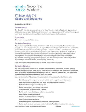
Trunking with 802.1QThis topic describes the basic functionality that is provided by IEEE 802.1Q trunking.Trunking with 802.1QRunning many VLANs between switches would require thesame number of interconnecting links.Green VLANGreen VLANRed VLANRed VLANBlue VLANBlue VLAN 2013 Cisco Systems, Inc.If every port belongs to one VLAN and you have several VLANs that are configured on switches,interconnecting these VLANs would require one physical cable per VLAN. When the number of VLANsincreases, so does the number of required interconnecting links. Ports are then used for interswitchconnectivity instead of attaching end devices.Trunking with 802.1Q (Cont.)Combining many VLANs on the same port is called trunking.A trunk allows the transportation of frames from different VLANs.Each frame has a tag that specifies the VLAN that it belongs to.Frames are forwarded to the corresponding VLAN based on the taginformation.Green VLANGreen VLANRed VLANRed VLANBlue VLANBlue VLAN 2013 Cisco Systems, Inc. 2013 Cisco Systems, Inc.Student Guide4-7
To fix this problem, you can use trunks that allow transportation of frames from different VLANs on thesame physical link.A trunk is a point-to-point link between one or more Ethernet switch interfaces and another networkingdevice, such as a router or a switch. Ethernet trunks carry the traffic of multiple VLANs over a single linkand allow you to extend the VLANs across an entire network. A trunk does not belong to a specific VLAN.It is a vehicle for VLANs between switches and routers. A special protocol is used to carry multiple VLANsover a single link between two devices. Cisco supports the 802.1Q trunking protocol for Ethernet interfaces.A trunk could also be used between a network device and a server or other device that is equipped with anappropriate 802.1Q-capable NIC.Trunking with 802.1Q (Cont.)Server with 802.1QCapable NIC802.1QTrunkVLAN 1802.1QTrunk802.1QTrunkVLAN 3VLAN 2802.1QTrunkVLAN 5VLAN 1VLAN 6 2013 Cisco Systems, Inc.You can configure an interface as trunking or nontrunking, or you can have it negotiate trunking with theneighboring interface.By default, all configured VLANs are carried over a trunk interface.4-8Interconnecting Cisco Networking Devices, Part 1 2013 Cisco Systems, Inc.
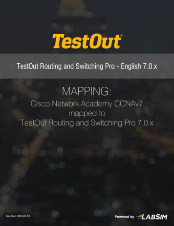
Trunking with 802.1Q (Cont.)Dest Src Type Data FCSOriginalFrameDest Src Tag Type Data FCSTaggedFrame 2013 Cisco Systems, Inc.When Ethernet frames are placed on a trunk, they need additional information about the VLANs that theybelong to. This task is accomplished by using the 802.1Q encapsulation header. The 802.1Q standard usesan internal tagging mechanism that inserts a 4-byte tag field into the original Ethernet frame between theSource Address and Type or Length fields. Because 802.1Q alters the frame, the trunking devicerecomputes the FCS on the modified frame.A 12-bit VLAN ID field within the tag is used to specify the VLAN to which the frame belongs.A tiny part of the 4-byte tag field, 3 bits, is used to specify the priority of the frame. The details arespecified in the IEEE 802.1p standard.Trunking with 802.1Q (Cont.)802.1QTrunkVLAN 1802.1QTrunk802.1QTrunkVLAN 3VLAN 2802.1QTrunkVLAN 5VLAN 1VLAN 6Native VLAN Untagged 2013 Cisco Systems, Inc. 2013 Cisco Systems, Inc.Student Guide4-9
An 802.1Q trunk and its associated trunk ports have a native VLAN value. When configuring an 802.1Qtrunk, a matching native VLAN must be defined on each end of the trunk link. 802.1Q does not tag framesfor the native VLAN. Therefore, ordinary stations can read the native untagged frames but cannot read anyother frame because the frames are tagged.NoteThe default native VLAN is VLAN 1.4-10 Interconnecting Cisco Networking Devices, Part 1 2013 Cisco Systems, Inc.
Creating a VLANThis topic describes how to create a VLAN.Creating a VLANCreate VLAN 2Fa0/3SwitchX#configure terminalSwitchX(config)#vlan 2SwitchX(config-vlan)#name SalesAdds VLAN 2 and names it "Sales" 2013 Cisco Systems, Inc.The table lists the commands to use when adding a VLAN.Command and VariableDescriptionvlan vlan-idID of the VLAN to be added and configured. Do not enter leading zeros. Youcan enter a single VLAN ID, a series of VLAN IDs that are separated bycommas, or a range of VLAN IDs that are separated by hyphens.name vlan-name(Optional) Specifies the VLAN name, which is an ASCII string from 1 to 32characters that must be unique within the administrative domain.For many Cisco Catalyst switches, you can use the vlan global configuration command to create a VLANand enter VLAN configuration mode. Use the no form of this command to delete the VLAN. The exampleshows how to add VLAN 2 to the VLAN database and how to name it “Sales.”To add a VLAN to the VLAN database, assign a number and name to the VLAN. VLAN 1 is the factorydefault VLAN. Normal-range VLANs are identified with a number between 1 and 1001. VLAN numbers1002 through 1005 are reserved for Token Ring and FDDI VLANs. VLAN IDs 1 and 1002 to 1005 areautomatically created and cannot be removed.Configurations for VLAN IDs 1 to 1005 are written to the vlan.dat file (VLAN database). You can displaythe VLANs by entering the show vlan privileged EXEC command. The vlan.dat file is stored in flashmemory.To add an Ethernet VLAN, you must specify at least a VLAN number. If no name is entered for the VLAN,the default is to append the VLAN number to the vlan command. For example, VLAN0004 would be thedefault name for VLAN 4 if no name is specified.For more details about the vlan (VLAN configuration mode) command, see the Cisco IOS LAN SwitchingCommand Reference at mcl/all 16.html. 2013 Cisco Systems, Inc.Student Guide4-11
Creating a VLAN (Cont.)SwitchX# show vlan id 2VLAN NameStatusPorts---- -------------------- --------------------------2SalesactiveFa0/2, Fa0/12VLAN Type SAIDMTUParent RingNo BridgeNo Stp BrdgMode Trans1 Trans2---- ---- ------- ----- ------ ------ -------- --- --------- ------ -----2enet 100002 1500 00 output omitted Verifies VLAN2 2013 Cisco Systems, Inc.After you configure the VLAN, validate the parameters for this VLAN.Use the show vlan id vlan number or the show vlan name vlan-name command to display informationabout a particular VLAN. The figure shows an example of using the show vlan command to display thecontents of the vlan.dat file. The “Sales” VLAN, which is VLAN 2, is highlighted in the example.Use the show vlan command to display information on all configured VLANs. The show vlan commanddisplays the switch ports that are assigned to each VLAN.For more details about the show vlan command, see the Cisco IOS LAN Switching Command Reference atthe following easemcl/all 14.html.4-12 Interconnecting Cisco Networking Devices, Part 1 2013 Cisco Systems, Inc.
Assigning a Port to a VLANThis topic shows how to assign a port to a VLAN.Assigning a Port to a VLANAssign FastEthernet0/3 to VLAN 2Fa0/3SwitchX#configure terminalSwitchX(config)#interface FastEthernet 0/3SwitchX(config-if)#switchport access vlan 2Assigns port FastEthernet0/3 to VLAN 2 2013 Cisco Systems, Inc.The table lists the commands to use when assigning a port to a VLAN.Command and VariableDescriptioninterface interfaceEnters interface configuration modeswitchport access vlanvlan numberSets a nontrunking, untagged, single VLAN Layer 2 interfaceWhen an end system is connected to a switch port, it should be associated with a VLAN, in accordance withthe network design. To associate a device with a VLAN, the switch port to which the device connects isassigned to a single-data VLAN and therefore becomes an access port.After creating a VLAN, you can manually assign a port or a number of ports to this VLAN. A port canbelong to only one VLAN at a time.NoteBy default, all ports are members of VLAN 1. 2013 Cisco Systems, Inc.Student Guide4-13
Assigning a Port to a VLAN (Cont.)SwitchX#show vlan briefVLAN Name---- 34vlan4 output omitted StatusPorts--------- veVerifies that port FastEthernet0/3 was assigned to VLAN 2 2013 Cisco Systems, Inc.Assigning a Port to a VLAN (Cont.)SwitchX#show interface FastEthernet0/3 switchportName: Fa0/3Switchport: EnabledAdministrative Mode: dynamic autoOperational Mode: static accessAdministrative Trunking Encapsulation: dot1qOperational Trunking Encapsulation: nativeNegotiation of Trunking: OnAccess Mode VLAN: 2 (Sales) output omitted Verifies VLAN membership on the Fa0/3 interface 2013 Cisco Systems, Inc.Use the show vlan privileged EXEC command to display the VLAN assignment and membership type forall switch ports. The show vlan command displays one line for each VLAN. The output for each VLANincludes the VLAN name, status, and switch ports.For more details about the show vlan command, see the Cisco IOS LAN Switching Command Reference semcl/all 14.html.Alternatively, use the show interfaces switchport privileged EXEC command to display the VLANinformation for a particular interface. The output in the example shows information about interface Fa0/3,where VLAN 2, named “Sales,” is assigned.4-14 Interconnecting Cisco Networking Devices, Part 1 2013 Cisco Systems, Inc.
For more details about the show interfaces switchport command, see the Cisco IOS LAN SwitchingCommand Reference at mcl/all 13.html. 2013 Cisco Systems, Inc.Student Guide4-15
Configuring an 802.1Q TrunkThis topic shows how to configure an IEEE 802.1Q trunk.Configuring an 802.1Q TrunkEnter the interface configuration mode.Configure the Fa0/11 interface as a VLAN trunk.Change the native VLAN from 1 to 99.Configure theinterface as a trunkFa0/11Switch XFa0/6Switch YSwitchX#configure terminalSwitchX(config)#interface FastEthernet 0/11SwitchX(config-if)#switchport mode trunkSwitchX(config-if)#switchport trunk native vlan 99 2013 Cisco Systems, Inc.Command and VariableDescriptioninterface interfaceEnters interface configuration mode.switchport mode trunkSets the interface type. The keyword trunk specifies a trunking VLAN Layer 2interface.switchport trunk native vlanvlan numberSets the native VLAN for the trunk in 802.1Q trunking mode.The example configures the FastEthernet0/11 port on SwitchX as a trunk port. Use the switchport modeinterface configuration command to set a Fast Ethernet port to trunk mode. Many Cisco Catalyst switchessupport DTP, which manages automatic trunk negotiation. DTP is a Cisco proprietary protocol. Switchesfrom other vendors do not support DTP. DTP is automatically enabled on a switch port when certaintrunking modes are configured on the switch port. DTP manages trunk negotiation only if the port on theother switch is configured in a trunk mode that supports DTP.The example shows the configuration of FastEthernet interface 0/11. The switchport trunk modecommand sets FastEthernet port 0/11 to trunk mode. The example shows the reconfiguration of the nativeVLAN. VLAN 99 is configured as native VLAN. Therefore, traffic from VLAN 99 will be sent untagged.Ensure that the other end of the trunk link (SwitchY) is configured for trunking and with the native VLANthat is changed to 99.NoteFor details on all of the parameters that are associated with the switchport mode interface command,visit mcl/all 15.html.4-16 Interconnecting Cisco Networking Devices, Part 1 2013 Cisco Systems, Inc.
Configuring an 802.1Q Trunk (Cont.)SwitchX#show interfaces FastEthernet0/11 switchportName: Fa0/11Switchport: EnabledAdministrative Mode: trunkOperational Mode: trunkAdministrative Trunking Encapsulation: dot1qNegotiation of Trunking: OnAccess Mode VLAN: 99Trunking Native Mode VLAN: 99 output omitted SwitchX#show interfaces FastEthernet0/11 trunkPortModeEncapsulation StatusNative vlanFa0/11 on802.1qtrunking99PortVlans allowed on trunkFa0/111-4094PortVlans allowed and active in management domainFa0/111-13 output omitted Verifies a trunk on the Fa0/11 interface 2013 Cisco Systems, Inc.To verify a trunk configuration on a switch, use the show interfaces switchport and show interfacestrunk commands. These two commands display the trunk parameters and VLAN information of the port.For more details about the show interfaces switchport and show interfaces trunk commands, see theCisco IOS Interface and Hardware Component Command Reference at ace/command/ir-s5.html. 2013 Cisco Systems, Inc.Student Guide4-17
VLAN Design ConsiderationsThis topic explains what you should be aware of when you segment your network with VLANs.VLAN Design ConsiderationsThe maximum number of VLANs is switch-dependent.VLAN 1 is the factory-default Ethernet VLAN.A use-dedicated VLAN is for the Cisco switch management IP address.Keep management traffic in a separate VLAN.Change the native VLAN to something other than VLAN 1. 2013 Cisco Systems, Inc.Typically, access-layer Cisco switches support up to 64, 256, or 1024 VLANs. The maximum number ofVLANs is switch dependent.Cisco switches have a factory-default configuration in which various default VLANs are preconfigured tosupport various media and protocol types. The default Ethernet VLAN is VLAN 1. Cisco DiscoveryProtocol advertisements are sent on VLAN 1. A good security practice is to separate management and userdata traffic because you do not want users to be able to establish Telnet sessions to the switch.If you want to communicate with the Cisco switch remotely for management purposes, the switch musthave an IP address. This IP address must be in the management VLAN, which by default is VLAN 1.A good security practice is to change the native VLAN to something other than VLAN 1 (for example,VLAN 98) and tag native VLAN traffic.4-18 Interconnecting Cisco Networking Devices, Part 1 2013 Cisco Systems, Inc.
VLAN Design Considerations (Cont.)When configuring a trunk link, consider the following:Make sure that the native VLAN for an 802.1Q trunk is the same on bothends of the trunk link.DTP manages trunk negotiations between Cisco switches.802.1QTrunkVLAN 1802.1QTrunk802.1QTrunkVLAN 3VLAN 2802.1QTrunkVLAN 6VLAN 5VLAN 7 2013 Cisco Systems, Inc.Ensure that the native VLAN for an 802.1Q trunk is the same on both ends of the trunk link. If the ends aredifferent, spanning-tree loops might result. If IEEE 802.1Q trunk configuration is not the same on bothends, Cisco IOS Software will report error messages. Also ensure that native VLAN frames are untagged.DTP offers four switchport modes: switch, trunk, dynamic auto, and dynamic desirable. A general guidelineis to disable autonegotiation. That is, do not use the dynamic auto and dynamic desirable switchport modes.For details on all of the parameters that are associated with the switchport mode interface command, go semcl/all 15.html. 2013 Cisco Systems, Inc.Student Guide4-19
Physical Redundancy in a LANThis topic describes how loops can affect performance in a switched LAN and introduces STP as a solution.Physical Redundancy in a LANLoops may occur in the network as part of a design strategyfor redundancy.ASegment ASegment 112Segment 2Segment 3Segment BSegment 43B4 2013 Cisco Systems, Inc.Adding switches to LANs can add the benefit of redundancy. Connecting two switches to the same networksegments ensures continuous operation if there are problems with one of the segments. Redundancy canensure the availability of the network at all times.However, when switches are used for redundancy in a network, loops are a potential problem. When a hoston one network segment transmits data to a host on another network segment, and the two are connected bytwo or more switches, each switch receives the data frames, looks up the location of the receiving device,and forwards the frame. Because each switch forwards the frame, each frame is duplicated. A loop results,and the frame circulates between the two paths without being removed from the network. The MAC tablesmay also be updated with incorrect address information, resulting in inaccurate forwarding.Suppose that a host named A sends a frame to a host named B. Host A resides on network segment A, andhost B resides on network segment B. Redundant connections between hosts are provided to ensurecontinuous operation if a segment fails. For this example, it is assumed that none of the switches havelearned the address of host B.Switch 1 receives the frame that is destined for host B and floods it out to switches 2 and 3. Switches 2 and3 both receive the frame from host A (via switch 1) and correctly learn that host A is on segments 1 and 2,respectively. Each switch forwards the frame to switch 4.Switch 4 receives two copies of the frame from host A: one copy through switch 2 and one copy throughswitch 3. Assume that the frame from switch 2 arrives first. Switch 4 learns that host A resides on segment3. Because switch 4 does not know where host B is connected, it forwards the frame to all of its ports(except the incoming port) and therefore to host B and switch 3. When the frame from switch 3 arrives atswitch 4, switch 4 updates its table to indicate that host A resides on segment 4. It then forwards the frameto host B and switch 2.4-20 Interconnecting Cisco Networking Devices, Part 1 2013 Cisco Systems, Inc.
Switches 2 and 3 now change their internal tables to indicate that host A is on segments 3 and 4. If theinitial frame from host A is a broadcast frame, both switches forward the frames endlessly. They would useall of the available network bandwidth and block transmission of other packets on both segments. Thissituation is called a broadcast storm.Physical Redundancy in a LAN (Cont.)RootASegment ASegment 11Segment 232BlockingXSegment 3Segment BSegment 4B4 2013 Cisco Systems, Inc.The solution to loops is STP, which manages the physical paths to given network segments. STP providesphysical path redundancy while preventing the undesirable effects of active loops in the network. STP is onby default in Cisco Catalyst switches.STP behaves as follows:STP forces certain ports into a standby state so that they do not listen to, forward, or flood data frames.The overall effect is that there is only one path to each network segment that is active at any time.If there is a problem with connectivity to any of the segments within the network, STP re-establishesconnectivity by automatically activating a previously inactive path,
Interconnecting Cisco Networking Devices, Part 1 Volume 2 Version 2.0 ICND1 Student Guide Part Number: 97-3243-01. Americas Headquarters Cisco Systems, Inc. San Jose, CA Asia Pacific Headquarters Cisco Systems (USA) Pte. Ltd. Singapore Europe Headquarters