Transcription
Computer PeripheralsSchool of Computer EngineeringNanyang Technological UniversitySingaporeThese notes are part of a 3rd year undergraduate course called "Computer Peripherals", taught at Nanyang Technological UniversitySchool of Computer Engineering in Singapore, and developed by Associate Professor Kwoh Chee Keong. The course coveredvarious topics relevant to modern computers (at that time), such as displays, buses, printers, keyboards, storage devices etc. Thecourse is no longer running, but these notes have been provided courtesy of him although the material has been compiled fromvarious sources and various people. I do not claim any copyright or ownership of this work; third parties downloading the materialagree to not assert any copyright on the material. If you use this for any commercial purpose, I hope you would remember where youfound it.Further reading is suggested at the end of each chapter, however you are recommended to consider a much more modern alternativereference text as follows:Computer Architecture: an embedded approachIan McLoughlinMcGraw-Hill 2011
Chapter 7.Magnetic Recording FundamentalsComputer memories are divided into two types. Main or working memories includingRAM's, ROM's and other semiconductor devices which are directly addressable by the CPU,and mass storage devices. Mass storage memories generally are not directly addressable by theCPU, have a slower access method, are non-volatile and often removable off-line and have amuch lower cost per bit. Mass storage devices may be classified into magnetic hard disks andfloppy disks, several types of magnetic tape drives, and various kinds of optical disk drives. Inadditional, there are the many varieties of card storage devices like magnetic cards, smartcards, ROM, RAM and flash memory cards, but these will not be discussed here. Except forthe CD-ROM in which data is represented by physical indentations or pits, practically all otherwrite-able mass storage devices make use of the magnetic or magneto-optical (M-O)characteristics of the recording media to store the required information. Thus we shall firstconsider some basic principles used in magnetic recording and the performance of the digitalrecording channel.7.1 Magnetic Material CharacteristicsWhen a piece of magnetic material is moved past a magnetic field, usually created by anelectromagnet, it becomes magnetised. Similarly, when the magnetised material is moved pastan unenergised coil, it induces a voltage across the coil. This is just Faraday's law ofelectromagnetic induction, which relates the voltage induced to the magnetic field strength. Anumber of parameters are used to characterise magnetic materials:(a)Coercivity Hc is the measurement the level of difficulty to magnetise thematerial. For storage media, a high coercivity is desired in order thatinformation stored will be preserved in the presence of stray magnetic fieldsthat may be present. High coercivity also implies that a strong magnetic fieldis needed to record information onto it. Magnets with high coercivity arecalled hard magnets.(b)Remanence Br is the amount of magnetisation that remains after themagnetic field is removed. Soft iron used for electromagnets are chosen tohave low remanence so that it will respond efficiently to the appliedelectromagnetic field.(c)Magnetic domains are small regions in the magnetic media which may bemagnetised independently of adjacent regions, so that adjacent domains canhave opposite polarities. The size or granularity of these domains have animportant bearing on the density of information that can be stored.(d)Flux reversal occurs when a change in polarity is encountered while movingfrom one domain to the next. The storage density of the media is measuredby the flux reversal per inch (frpi) or the flux change per inch (fcpi).www.lintech.org
Magnetic Recording Fundamentals2Figure 0-1 shows the B-H characterisation curves for soft and hard magnetic materials.BBBrBrHHHcSOFT MAGNETHc 10 OeHcHARD MAGNETH c 100 OeFigure 0-1. B-H magnetisation curves7.2 Read/Write headThe "guts" of a magnetic recording system are: the write head, the magnetic medium,and the read head. (The write head could be the same as the read head and usually has beenthe case for disk drives.) The write head is driven by a current source that carries theinformation to be stored. The write head radiates flux, which changes the state of magnetization of the magnetic medium immediately under the head. Actually, since the head ismoving with respect to the magnetic medium, any point on the magnetic medium retains thestate of magnetization corresponding to the last flux it experienced from the write head as thehead moves away from that point.On a rigid disk, the disk moves in a circular motion under the head. Information isstored on the disk in concentric tracks, the width of a track roughly being governed by the sizeof the write head. The density of recording per sq inch (known as areal density) is the productof the number of tracks per inch (tpi) and the linear density of information along a trackmeasured in bits per inch (bpi). Typical numbers for today's high end (i.e., expensive) rigiddisk drives are: 3,000 tpi and 30,000 bpi.The current into the write head induces a magnetization pattern on the track immediatelybelow the write head. When a track is to be read, a read head is positioned over the track.Then, the magnetization pattern "frozen" on that track radiates flux that is sensed, or "read,"by the read head. The read head produces a voltage that is symptomatic of the magnetizationon the track being read. There are primarily two types of read head: inductive heads whichcontain coils of very fine wire and which produce a voltage proportional to the time derivativeof the flux that passes through its coils, and magneto-resistive (MR) heads which produce avoltage directly proportional to the flux sensed by the head. MR heads produce larger readvoltages than inductive heads, but have a limited dynamic range for linear operation. Onlyinductive heads have been used for writing, to this date.www.lintech.org
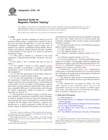
Magnetic Recording Fundamentals3Consider the familiar audio cassette tape recorder in Figure 0-2. The recording/playbackhead is made of easily magnetised ferrite material and has a small air-gap γ at the point whereit comes into contact with the recording tape, δ 0. When energised, the coil winding on thestructure is used to create a strong and concentrated magnetic field on the recording media asit moves along with a velocity v. During the playback mode, this coil detects the inducedvoltages.iwmagnetic fluxgapγδmedia velocityvfringing fieldn sn sn shead distancerecording mediamagnetic dipolessubstrateFigure 0-2 Basic Ring read/write head.The recording media in this case is a length of MYLAR (plastic) tape coated with apowdered ferric oxide compound which is magnetisable and has high remanence. This layer ofmagnetic material in the unmagnetised state may be conceived as made up of dipoles, tinymagnets with N-S poles randomly positioned. Under the influence of the external magneticfield, these dipoles will align their N-S poles in line with the applied field thus becomingmagnetised. Upon removal of the applied field some of these dipoles remain aligned.By either increasing the rate v the media is moved across the head, or by decreasing thegranularity of the magnetic material, (i.e. making the tiny magnets smaller), we can recordfaster changes in the applied magnetic field, that is, the frequency response is increased. Fordigital data, the density of the stored information increase with decrease in the granularity ofthe magnetic media.With a weak field, only a small number of the dipoles retain their alignment. As thefield gets stronger, more and more of them will remain aligned, that is, the stored magneticfield increases. For audio (analogue) recording, the variation in the audio signal levels arerecorded in this linear region of the magnetic behaviour. A saturation level is reached whenincreases in the applied field does not result in a corresponding increase in the stored magneticfield. Digital recording generally operate in the saturation region.www.lintech.org
Magnetic Recording Fundamentals47.3 The Digital Read/Write rceDecoderChannelDecoderDetectorMagnetic diskMagnetic tapeOptical DiskCD-ROMetcReadEqualizerStorageDeviceFigure 0-3 The Digital Recording channelDigital recording systems may be considered as communications channels. There is an inputsignal and an output signal which is a transformed and noisy version of the input. Quotingfrom a paper by Berlekamp "Communication links transmit information from here to there,Computer memories transmit information from now to then." Figure 0-3 show the overallblock diagram of the digital read/write channel. The source data to be recorded or saved isprepared by the CPU, which also provides the storage device with information concerning theaddress of the storage locations. Compression and other source data preprocessing takes placebefore the data passes into the channel encoder which adds error-correcting bits and convertsthe data stream into a form suitable for recording. This signal is passed through theequalisation filters, and amplified as the write current for the recording head, creating thepattern of magnetic fluxes reversals on the storage medium.To recover the stored data at the output, a reverse sequence takes place. Starting at thestorage medium, the flux reversals are sensed by the magnetic head. The pulses aredemodulated, equalised, decoded and finally presented at the output as the read data.In digital recording, the magnetic medium is saturated and flux reversals are used torepresent the digital information. Figure 0-4 shows the relationship between the write signal,flux changes and subsequent induced current in the read mode.www.lintech.org
Magnetic Recording Fundamentals5Write currentiwFlux transitionsMagnetizationNS SN NS SN NS SN NSRead voltageeoFigure 0-4. Magnetic write and read waveforms.7.3.1 Write ProcessDuring the write process, a write current iw is passed through the coil. Since the currentneeds a finite time to build up and the media is moving under the head, the result is amagnetic transition with a finite rise-time as shown in Figure 0-4. We can represent thechange in magnetic flux mathematically asM(x-x0)Disks and tapes employ the longitudinal recording method illustrated above in which theflux lines of the magnetic field are oriented in the direction of the motion of the media.Although higher recording densities are attained using the vertical or perpendicular recordingmethod in which the flux lines are perpendicular to the surface of the media this method ismore difficult and correspondingly more expensive to implement. As shown above, thedirection of the write current determines the polarity of the magnetisation of the recordingmedium. When the current reverses, it creates a flux reversal.www.lintech.org
Magnetic Recording Fundamentals67.3.2 Read ProcessDuring the read process, the magnetisation on the recording surface is detected by the headand some of the magnetic flux is diverted through the coil, producing an induced voltage eowhich is proportional to the rate of change of flux as seen also in Figure 0-4. Mathematicallywe can represent this read pulse as e0 CV D( x ) M ( x x 0)dx x where D is a the efficiency of the read head. As it is, these detected current pulses are hard todistinguish from noise pulses found in magnetic media and techniques are required to properlyencode and decode the data for magnetic recording purposes. Under ideal conditions, the peakof the read pulse indicates the position of the flux transition. Peak detection of this signal isimplemented by first converting the signal to positive pulses with full wave rectification.These pulses are differentiated and detected with a zero crossing detector as shown in Figure0-5.Read signale0DifferentatedoutputPW50Weaker read signalComparatoroutputThis edgefor strobeFigure 0-5. Model of read signal used with peak detection.Mathematical models of the read pulse are used in the design of the demodulation andequalisation circuits, and an important parameter used in describing the pulse is the width ofthe pulse at 50% amplitude, PW50. The Lorentzian model is the most common mathematicalmodel for an isolated transition response. The Lorentzian pulse shape can be expressed as:www.lintech.org
Magnetic Recording Fundamentalsh( t ) 7A1 (2t / PW50 ) 210.90.80.70.60.50.40.30.20.10-6-4-202467.4 Peak Detection SystemsOne major problem affecting the read signal is the effects of noise. It is common toassume that the noise in the system is additive and Gaussian. Usually, it is also assumed thatthe noise consists of two components: a Gaussian white noise component due to theelectronics read (i.e., receiver) side, and a Gaussian coloured component due to the medium.The spectral characteristics of this coloured noise are essentially the same as would beobtained from passing white noise through the linear transfer function characterizing thesystem. More complicated models for the noise exist, but we will not go into the discussion.The design of the modulation, coding and signal processing in past magnetic recordingproducts has been driven by the detector chosen to detect the transitions in the channel inputwaveform. This detector, called a peak detector has the advantage of being both robust andextremely simple to implement. However, by its very nature, it works best at low lineardensities. A block diagram of a typical peak detector is shown in Figure 0-6: Block diagram ofa peak detector.H1(f)FWR TH2(f)d/dtZCDFigure 0-6: Block diagram of a peak detectorwww.lintech.organd
Magnetic Recording Fundamentals8The are two path through the detector. The first path is used to qualify a peak, i.e., toensure that the peak has sufficient amplitude. This path consists of a linear filter, Hl(f), a fullwave rectifier (FWR), and a threshold testing circuit. The bottom path is used to locate thepeak by differentiating the signal after the linear filter H2(t) which remove most of the noiseand then passing the differentiated signal through a zero crossing detector (ZCD).The systemonly accepts a peak if the amplitude was large enough to the qualification test.7.4.1 Data and Clock RecoveryOnce a peak is detected by the peak detector, it is thought to be due to a transition in theinput waveform. A device called a phase-lock loop (PLL) is used to derive timing from theposition of the detected peaks. The PLL produces a clock of period Tb seconds by which toidentify channel bit intervals (sometimes called "bit cells"). Then, if an output pulse is locatedin a bit interval, that bit interval is said to contain a transition.The output of the peak detector is used as an input to the PLL, and the output clockproduced by the PLL is constantly being adjusted so that the average peak position is centeredwith respect to the edges of the bit interval.The data and clock information, stored by the schemes described later in the followingsection, must be recovered and separated during the read operation. A phase-locked loop(PLL) as shown in Figure 0-7 is used for this purpose.EncodeddataMuxPhasedetectorVCOVCO clockMuxSystemclockDecoder andmissing clockdetectorRead clockRead dataMissing clockFigure 0-7. Phase-locked loop (PLL).The phase difference between the incoming signal frequency and the frequency of thevoltage-controlled oscillator (VCO) is averaged out by the low-pass filter, forming a DCvoltage to control the VCO. The output of the VCO is divided down to a frequency equal tothe incoming signal frequency and fed into the phase detector. The VCO and the incomingsignal are thus locked together. Any variation in frequency of the incoming signal results in achange in the phase difference which produces a error voltage to the VCO, causing it to trackthe frequency of the incoming signal.The VCO, which is synchronised to the encoded data stream read back from the drive, isused to generate two windows, one for the clock and the other for the data pulses. Sync bytes,written as part of the record format are used to identify the two sets of pulses.www.lintech.org
Magnetic Recording Fundamentals97.4.2 Bit Shifting[TC1]During read back, the signals are very weak and the magnetic head may be considered tobe operating linearly. Each read pulse can be considered independently for analysis. As therecording density increases, these read pulses are crowded together, giving rise to a source ofproblem known as peak shift or bit shift. Referring to Figure 8.1,[TC2] it will be seen that ateach flux transition, the polarity of the domain changes setting two like poles adjacent to eachother. As the superposition of the two read pulse, the result is that the bits will be stored in aposition shifted from the nominal bit cell position. The actual amount of shift depends on thebit pattern and has to be compensated for.We can look at the problem by considering a sequence of two read pulses. When thewaveforms of the two signals are superimposed on each we notice two effects occurring.Firstly, the amplitude of the signals is reduced. More significantly, the position of the peaksare shifted away from each other.Shiftd / tShiftτFigure 8.0-8. Two adjacent bits superimposed resulting in bit shift.If one examines the waveform produced by the linear superposition of two Lorentzianpulses (of opposite sign) separated by αPW50 seconds, one finds that this waveform willcontain two peaks separated by βPW50 seconds, where β α. The parameters α and β arerelated by the formulaβ α2 1 2 1 α2 α43which for small α becomesβ 1 α23For α much greater than 1, β is approximately equal to α, but as α approaches zero, βapproaches a fixed, limiting distance given by the value. Thus, the peaks will be centered intheir bit interval only at low densities.www.lintech.org
Magnetic Recording Fundamentals10The usual method of eliminating errors from bit shift is by write pre-compensation. Inthis technique, the amount of shift is determined from the bit pattern and a deliberate shift inthe opposite direction is introduced during recording to compensate for it. The amount of shiftis a function of the pattern as well as the proximity of the neighbouring pulses. By assuming amathematical model of the read pulse waveform, these values can be calculated. Thesecompensation values are stored in a lookup table which would list all possible bit patterns, forsay a group of eight bits, and the shift required. 'Early' and 'Late' write compensation is usuallyincorporated into the controller circuitry. These errors produced by the interference betweenneighbouring data bits is known as intersymbol interference (ISI).7.5 Data EncodingThere are many ways of encoding the data as a function of flux reversals. The simplestwould be to represent each 1 with a pulse leaving the signal low for each 0. This is the returnto-zero (RZ) code as the level always drop back to the zero state. If the level for the 1 is heldhigh for the whole bit period, we have the special case of the non-return-to-zero (NRZ). In theearly days of magnetic recording many codes were introduced. Although many of these arenow obsolete, new codes are still being proposed mathematically in the search for improvedperformance. The design of new codes take into account two main factors:(i)The various parameters like density, immunity to noise and timinginaccuracies, complexity of code etc. have to be balanced against each other,and the design is a compromise of trade-offs depending on the specificapplication and environment.(ii)Many codes are protected by patent and sub-optimal solutions are proposedto avoid license fees.7.5.1 Common Code DefinitionsThe following section, together with Fig 0-9, defines some of the various codes used indigital recording. Generally, the write waveforms are used in the representation. The twolevels of saturation are depicted vertically and the horizontal scale represents the distancemoved by the medium under the head, or equivalently, time. The horizontal unit used is the bitcell width and is defined the period between two clock transitions. Within the bit cell, thelevel can be "up" or "down", and there may or may not be a transition, called the datatransition. Various combinations of clock and data transitions are possible.www.lintech.org
Magnetic Recording Fundamentals11Bit ROFig 0-9. Recording codes.(a)Return to Zero (RZ)One saturation level is designated as the zero level.(b)(c)0:there is no flux transition within the whole bit cell1:is represented by the occurrence of a downwards transition within the bit cell.As the level is always at the zero level, an upwards transition is required at thebeginning of the bit cell. RZ is functionally the same as Return to Saturation (RS). Transitions occur atboth cell boundaries and mid-cell.Non-Return to Zero (NRZ), Non-Return to Zero-Level (NRZ-L)0:Down level (baseline)1:Up level The Non-return to zero (NRZ) technique of recording is the simplest and mostefficient, but it is not self-clocking, and we cannot obtain the bit cellinformation from it. Flux reversals occur only at mid-cells (or cell boundariesin some implementation).Non-Return to Zero, Invert (NRZI) or Non-Return to Zero, Mark (NRZ-M)0:No transition anywhere, magnetic state remains the same as in the previous bitcell, whether up or down.www.lintech.org
Magnetic Recording Fundamentals(d)(e)121:A transition occurs in the middle of the bit cell. The direction of the transitionis not important. A long sequence of zeroes will result in no transitions during that period andthe loss of clock synchronization. 9-track parallel tape drives can use NRZI asthe track for the parity bit will always have a transition when a long sequenceof (00)h is written.Phase Modulation (PM), Bi-Phase, Transition (Biφ-T) or Manchester code.0:Up-going transition in mid-cell.1:Down-going transition in mid-cell. Clock transitions, at the cell boundaries, are used to enable the proper directionfor the data transition. For a series of 1's or 0's, an addition transition has to takeplace at the cell boundary in order that the correct direction of the transition cantake place at the cell centre. As each bit could require up to two transitions toencode, this is not an efficient technique. There is always a transition at midcell, and this can be used for the clocking purposes. Phase encoding (PE) is for9-track tapes and is a simple self-clocking encoding technique.Frequency Modulation (FM) or Bi-Phase, Mark (Biφ-S).0:Transition at mid-cell, direction is not important.1:No transition at mid-cell, level is not important. A clock transition is always present at the cell boundaries.www.lintech.org
Magnetic Recording Fundamentals (f)13Frequency modulation (FM) is similar to PE in efficiency but does not use thedirection of the flux transition. Except for the clock transitions, FM is similar toNRZI, with the representations for 1 and 0 interchanged. FM is the encodingmethod used for single-density floppy disks.Modified Frequency Modulation (MFM) or Miller code.0:No transition.1:Transition at mid-cell, exactly as in NRZI. Since a sequence of zero bits will not have any transitions, introduce a fluxtransition at cell boundaries to separate two adjacent 0 bits. In this way therewill be at least one flux transition in any two bit cell period, making it selfclocking. Modified FM (MFM) was introduced by IBM to increase the densityof recording by removing most of the flux transitions at bit cell boundaries inthe FM technique, thus reducing the fcpi to an average of one. MFM is thestandard encoding technique for double-density floppy disks and the earlierWinchester hard disks. It should be observed that MFM is actually amodification of NRZI and not FM coding.Modified MFM (M2FM).(g) Modified MFM (M2FM) was introduced by Shugart Associates, one of theearliest manufacturers of floppy disk drives. It eliminates the flux transition atthe bit cell boundary if it is preceded by a cell boundary flux transition in theprevious cell. However IBM continued to use the MFM method, which becamethe de facto industry standard.7.5.2 Run-Length-Limited Encoding (RLL)As mentioned earlier, intersymbol interference places an upper limit on the density of the fluxtransitions that a particular head-medium system can achieve. Bit shift effects can becompensated with an early write signal performed on the code prior to the write process.During the read process we can pass the detected pulses through a equalization filter to "slim"them, thus reducing the effects of pulse superposition.Another way of improving the recording density makes use of run-length limitedencoding schemes. This constrained sequences result in a two-level write waveform for whichthe minimum and maximum intervals between transitions are fixed.Run-length limited are designated as:RLL(d, k, m, r)and are often shortened toRLL(d, k)whered Minimum number of consecutive zeroes allowed (including clock).k Maximum number of consecutive zeroes allowed (including clock).m Minimum number of data bits to be encoded.n Number of code bits (including clock) for each of the m data bits.r Number of different word lengths in a variable length code.www.lintech.org
Magnetic Recording Fundamentals14DR Density Ratio. Data bits per flux reversal.bit per inch (BPI) m DR (d 1) x n flux changes per inch (FCPI)FR Frequecy Ratio.FR maximum time between transitions k 1 minimum time between transitions d 1w Detection window expressed as a percentage of a data bit cell m w 100 n Table 1 gives the mathematical calculations performed for a number of popular d, kconstrained codes.CodenameWhere useddkmnrDRFRwNRZIEarly disks, tapes0 1111.0 100%FMFloppy disks011210.52.050%GCRTape024510.83.080%MFMDisks, IBM 1,7)QIC Tape172311.334.064%EFMCompact Disks21081711.413.6747%Table 1 Performance of some RLL codes.We shall look at some popular RLL codes below:7.5.3 Group-coded recording (GCR) or RLL(0,2)GCR is another self-clocking modification of NRZI. It will be seen that we can translateeach 4-bit group into a 5-bit group with the help of Table 2.[TC3] It will be noted that the 5-bitcode are defined such that the resultant data stream will not contain more than twoconsecutive zeroes. The GCR-translated data can be recorded using NRZI without introducingany additional flux transitions and is thus very efficient. GCR is the recording method used inhigh density tape drives such as the IBM 3420. The penalty to be paid is in the complexity ofthe encoding/decoding logic.www.lintech.org
Magnetic Recording FundamentalsData nibble00000001001000110100010101100111GCR code1100111011100101001111101101011011010111Data nibble1000100110101011110011011110111115GCR code1101001001010100101111110011010111001111Table 2 GCR encoding table.7.5.4 Run-length-limited 1,7The rate 2/3 (1,7) code is arguably the most popular (d,k) code in use today. Severalvariations of this code exist. A simple and elegant description, due to Jacoby, begins with theencoding table in Table 3.Data nibble00011011RLL (1,7) code101100001010Data nibble00 0000 0110 0010 01RLL (1,7) code101 000100 000001 000010 000Table 3 RLL(1,7) encoding table.When the encoder is ready to encode a pair of user data bits, it "looks ahead" to the nextpair of user data bits to see if it exist in the right side of Table 3 for both pairs. If the combinedword is not found, use the left side for encoding.As illustrated for a rate m/n code, the decoding of a code word of length n depends onthe contents of a decoder window that contains the code word in question, as well as a fixednumber of past and future code words ("look back" and "look-ahead"). In the case of the (1,7)code, the decoder decodes the current three-bit code word by looking ahead at the next twoupcoming code words. In this way, a single incorrectly detected code symbol can propagateinto a burst of at most six user bits (in fact, the burst length does not exceed five user bits).7.5.5 Run-length-limited 2,7Another data encoding used together with NRZI modulation encoding in several diskdrive products is a rate 1/2 (2,7) code. One encoding and decoding tree for such a code isgiven in Figure 0-10. RLL 2,7 Coding Tree.It is easily seen that the code rate is 1/2 (every code word contains exactly twice as manybinary digits as the information sequence it represents) and that any concatenation of thevariable length code words satisfies the (2,7) constraint (each 1 in every code word is followedby at least two 0s, and no code word begins with more than four 0s or ends in more than threewww.lintech.org
Magnetic Recording Fundamentals160s). It can also be verified that every information sequence can be decomposed uniquely into asequence of variable length strings in the tree. In addition, the decoding errors due to a singlecode symbol in error cannot affect more than four user 00100)0(00100100)1(00001000)Figure 0-10. RLL 2,7 Coding Tree.The coding tree for the RLL 2,7 code is given Figure 8.2 and Figure 8.3 shows the writewaveforms. Although each data bit is encoded into 2 channel bits, a 50% improvement in datadensity is obtained when compared to MFM coding when we only consider the size of themagnetic domain (fcpi).Figure 0-11. Run length limited coding (2,7).www.lintech.org
Magnetic Recording Fundamentals17Prior to a few years ago, no general theory existed for the design of data encoding codes(such as (d,k) c
The recording/playback head is made of easily magnetised ferrite material and has a small air-gap γ at the point where it comes into contact with the recording tape, δ 0. When energised, the coil winding on the structure is used to create a strong and concentrated magnetic field on th