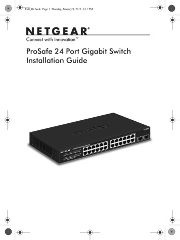
Transcription
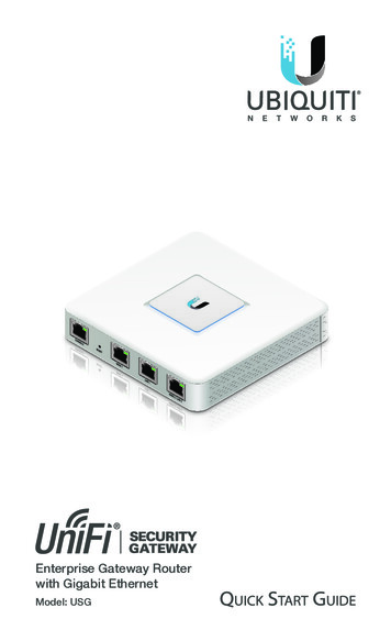
Enterprise Gateway Routerwith Gigabit EthernetModel: USG
IntroductionThank you for purchasing the Ubiquiti Networks UniFi Security Gateway. This Quick Start Guide is designed to guideyou through installation and also includes warranty terms.Package ContentsUniFi Security GatewayPower Adapter(12V, 1A)Power CordEnterprise Gateway Routerwith Gigabit EthernetModel: USGScrews(Qty. 2)Screw Anchors(Qty. 2)Quick Start GuideTERMS OF USE: All Ethernet cabling runs must use CAT5 (or above). It is the professionalinstaller’s responsibility to follow local country regulations and indoor cabling requirements.
UniFi Controller System Requirements Microsoft Windows 8, Mac OS X, or Linux Java Runtime Environment 1.6 (or above) Web Browser: Mozilla Firefox, Google Chrome, MicrosoftEdge, or Microsoft Internet Explorer 11 UniFi Controller software v5.4 or higher (available at:www.ubnt.com/download/unifi)Network RequirementsA UniFi Cloud Key or management station running the UniFiController software, located either on-site and connected tothe same Layer-2 network, or off-site in the cloud or NOCUniFi Cloud Key(UniFi 0WLANUSG(DHCP Server)WANREFRESH RATEGUI 5.0.20750.90CURRENT SITE2 ernet29.62295ACTIVE 413700 MbpsTHROUGHPUT0200 18ACTIVE DEVICESInactive00PendingACTIVE DEVICESInactive00PendingSPEED TESTDOWNLOAD THROUGHPUT & LATENCYDEVICES ON 2.4 GHZ CHANNEL40 Mbps40 msec30 Mbps30 msec20 msec20 Mbps0Mbps123456789101110 msec10 Mbps24 HRSNOW12 HRSAvg/Max Throughput0 msecDEVICES ON 5 GHZ CHANNELLatencyUPLOAD THROUGHPUT & LATENCY1 Mbps40 msec0.8 Mbps30 msec0.6 Mbps20 msec0.4 Mbps0 Mbps364044485256601001041081121161201246412810 msec0.2 Mbps24 HRS12 HRSDEVICESNOW0 53157161165DEEP PACKET aptopNASOther234222213.2 GBTRAFFICStreaming MediaNetwork ProtocolsWeb / Web 2.0Security UpdateUnknownOther6.49 GB3.44 GB921 MB813 MB1.25 GB379 MBRemote Access toUniFi ControllerSample Network DiagramAll UniFi devices support off-site management controllers. Forsetup details, see the User Guide on our website at:www.ubnt.com/download/unifi
Hardware OverviewPorts PanelInterfaceDescriptionConsoleRJ45 serial console port for CLI management.Use a RJ45‑to‑DB9 serial console cable toconnect the Console port to your computer.Then configure using the following settings: Baud rate 115200 Data bits 8 Parity NONE Stop bits 1 Flow control NONEResetResets to factory defaults. The UniFi SecurityGateway should be powered on. Press and holdthe Reset button for about 10 seconds untilthe right LED on the WAN 2 / LAN 2 port startsflashing and then becomes solidly lit. After afew seconds, the LED will turn off, and the UniFiSecurity Gateway will automatically reboot.WAN 1Supports 10/100/1000 Ethernet WANconnections. Default setting is DHCP client.LAN 1Supports 10/100/1000 Ethernet LANconnections. Default setting is DHCP Server.Server IP: 192.168.1.1/24WAN 2 /LAN 2Supports 10/100/1000 Ethernet connections.Configure the port using the UniFi SecurityGateway configuration interface.
LEDsStatusPowerEthernetConsoleStatus lly Booted; Not AdoptedBlueAdopted and ProvisionedAlternatingWhite/BlueDevice Firmware isUpgradingBlueFlashingDevice Locator Activatedfrom UniFi ControllerOffPower OffGreenPower OnOffNo LinkAmberLink Established at10/100 MbpsAmberFlashingLink Activity at10/100 MbpsGreenLink Established at1000 MbpsGreenFlashingLink Activity at1000 MbpsPowerSpeed/Link/Act
Hardware InstallationThe UniFi Security Gateway can be used on a level, stablesurface, or mounted to a wall with the included screws andanchors. If you are not going to mount the UniFi SecurityGateway on a wall, then skip to the section, Connecting Power.WARNING: To reduce the risk of fire or electric shock, donot expose this product to rain or moisture.WARNING: FAILURE TO PROVIDE PROPER VENTILATIONMAY CAUSE FIRE HAZARD. KEEP AT LEAST 20 MM OFCLEARANCE NEXT TO THE VENTILATION HOLES FORADEQUATE AIRFLOW.Wall-MountingTo mount the UniFi Security Gateway on a wall, you will need adrill, a 6 mm drill bit, and a Phillips screwdriver.1. Use a 6 mm drill bit to drill two holes 90 mm apart. Insert aScrew Anchor into each hole.90 mm*640-00120-04*640-00120-04
2. Use a Phillips screwdriver to secure a Screw into eachanchor. Leave a clearance of approximately 3 mm betweenthe screw head and the wall.3 mm3. Position the UniFi Security Gateway over the Screws, andinsert the Screws into the wall-mount slots located on thebottom of the UniFi Security Gateway. Then slide the UniFiSecurity Gateway down to lock it into place.CVD12
Connecting Power1. Connect the Power Adapter to the power port.2. Connect the Power Cord to the Power Adapter. Connect theother end of the Power Cord to a grounded power source.
Network Connections1. Connect an Ethernet cable from a broadband modem orWAN to the WAN 1 port.2. Connect an Ethernet cable from a network switch to theLAN 1 port.Note: LAN 1 is set to DHCP Server by default.
Software InstallationDownload and install the latest version of the UniFi Controllersoftware at: www.ubnt.com/download/unifiFrom a management station connected to the same Layer‑2network, launch the installer and follow the on-screeninstructions.Note: If you already have UniFi Controller v5.4 or higherinstalled, go to the section, Adopting the UniFi SecurityGateway.1. The Ubiquiti UniFi Controller window will appear. ClickLaunch a Browser to Manage the Network.2. Select your country and time zone. Alternatively, you canclick restore from a previous backup to use a file thatcontains your backup settings. Click Next.
3. The UniFi Controller will discover the UniFi SecurityGateway with the default IP Address,192.168.1.1. Select thedevice, and click Next.4. Create an SSID (wireless network name) and SecurityKey. Click Next. If you do not have any UniFi APs on thenetwork, click Skip.
5. Create an Admin Name and Password for super adminaccess to the UniFi Controller. Confirm the Password, andclick Next.6. Review the UniFi Controller settings. Click Finish tocomplete the UniFi Setup Wizard.
7. The login screen for the UniFi Controller will appear. Enterthe Admin Name and Password that you created in theUniFi Setup Wizard. Click Login.The UniFi Controller dashboard window will appear.Adopting the UniFi Security Gateway1. From the UniFi Controller dashboard, click Devices in theleft menu bar.
2. In the Devices window, locate UniFi Gateway in the list ofdevices under the Model column. To adopt and provisionthe gateway, click Adopt.3. The Status Indicator on the UniFi Security Gateway will turnblue to confirm that it is successfully adopted.
Optional WAN Port Configuration via Layer 3By default, the WAN port is set to DHCP so it can be assignednetwork settings by the service provider. To change thesetting, connect a computer directly (or through a switch) tothe LAN 1 port of the UniFi Security Gateway.1. From a web browser, gohttps://setup.ubnt.comto https://setup.ubnt.com/2. The UniFi Gateway login window will appear. Enter yourUsername and Password. Click Sign In.Note: If the UniFi Security Gateway has not beenadopted by a UniFi Controller, the login window willbe skipped and the Setup window will appear.3. In the Setup window, click Edit Configuration to configurethe WAN port to DHCP, Static IP, or PPPoE.For information on using the UniFi Controller software, refer tothe User Guide located on our website at:www.ubnt.com/download/unifi
SpecificationsUniFi Security GatewayDimensionsWeightNetworking InterfacesSerial Console PortData PortsMax. Power ConsumptionPower SupplySupported Voltage RangeLEDsSystemSerial Console PortData PortsLayer 3 ForwardingPerformancePacket Size: 64 BytesPacket Size: 512 Bytesor LargerProcessorSystem MemoryOn-Board Flash StorageRackmountOperating TemperatureOperating HumidityCertifications135 x 135 x 28.3 mm(5.32 x 5.32 x 1.11")366 g (12.9 oz)(1) RJ45 Serial Port(3) 10/100/1000 Ethernet Ports7W12VDC, 1A Power Adapter (Included)9 to 24VDCStatusPowerSpeed/Link/Activity1,000,000 pps3 Gbps (Line Rate)Dual-Core 500 MHz, MIPS64with Hardware Accelerationfor Packet Processing512 MB DDR2 RAM2 GBYes-10 to 45 C (14 to 113 F)10 to 90% NoncondensingCE, FCC, IC
Safety Notices1.Read, follow, and keep these instructions.2.Heed all warnings.3.Only use attachments/accessories specified by the manufacturer.WARNING: Failure to provide proper ventilation maycause fire hazard. Keep at least 20 mm of clearance nextto the ventilation holes for adequate airflow.WARNING: To reduce the risk of fire or electric shock, donot expose this product to rain or moisture.WARNING: Do not use this product in a location that canbe submerged by water.WARNING: Avoid using this product during an electricalstorm. There may be a remote risk of electric shock fromlightning.Electrical Safety Information1.Compliance is required with respect to voltage, frequency, and currentrequirements indicated on the manufacturer’s label. Connection to adifferent power source than those specified may result in improperoperation, damage to the equipment or pose a fire hazard if thelimitations are not followed.2.There are no operator serviceable parts inside this equipment. Serviceshould be provided only by a qualified service technician.3.This equipment is provided with a detachable power cord which hasan integral safety ground wire intended for connection to a groundedsafety outlet.a.Do not substitute the power cord with one that is not the providedapproved type. Never use an adapter plug to connect to a 2-wireoutlet as this will defeat the continuity of the grounding wire.b.The equipment requires the use of the ground wire as a part of thesafety certification, modification or misuse can provide a shockhazard that can result in serious injury or death.c.Contact a qualified electrician or the manufacturer if thereare questions about the installation prior to connecting theequipment.d.Protective earthing is provided by Listed AC adapter. Buildinginstallation shall provide appropriate short-circuit backupprotection.e.Protective bonding must be installed in accordance with localnational wiring rules and regulations.
Limited WarrantyUBIQUITI NETWORKS, Inc (“UBIQUITI NETWORKS”) warrants that theproduct(s) furnished hereunder (the “Product(s)”) shall be free from defectsin material and workmanship for a period of one (1) year from the dateof shipment by UBIQUITI NETWORKS under normal use and operation.UBIQUITI NETWORKS’ sole and exclusive obligation and liability underthe foregoing warranty shall be for UBIQUITI NETWORKS, at its discretion,to repair or replace any Product that fails to conform to the abovewarranty during the above warranty period. The expense of removal andreinstallation of any Product is not included in this warranty. The warrantyperiod of any repaired or replaced Product shall not extend beyond itsoriginal term.Warranty ConditionsThe above warranty does not apply if the Product:(I)has been modified and/or altered, or an addition made thereto,except by Ubiquiti Networks, or Ubiquiti Networks’ authorizedrepresentatives, or as approved by Ubiquiti Networks in writing;(II)has been painted, rebranded or physically modified in any way;(III)has been damaged due to errors or defects in cabling;(IV)has been subjected to misuse, abuse, negligence, abnormal physical,electromagnetic or electrical stress, including lightning strikes, oraccident;(V)has been damaged or impaired as a result of using third partyfirmware;(VI)has no original Ubiquiti MAC label, or is missing any other originalUbiquiti label(s); or(VII) has not been received by Ubiquiti within 30 days of issuance ofthe RMA.In addition, the above warranty shall apply only if: the product has beenproperly installed and used at all times in accordance, and in all materialrespects, with the applicable Product documentation; all Ethernet cablingruns use CAT5 (or above), and for outdoor installations, shielded Ethernetcabling is used, and for indoor installations, indoor cabling requirementsare followed.ReturnsNo Products will be accepted for replacement or repair without obtaininga Return Materials Authorization (RMA) number from UBIQUITI NETWORKSduring the warranty period, and the Products being received at UBIQUITINETWORKS’ facility freight prepaid in accordance with the RMA process ofUBIQUITI NETWORKS. Products returned without an RMA number will notbe processed and will be returned freight collect or subject to disposal.Information on the RMA process and obtaining an RMA number can befound at: www.ubnt.com/support/warranty
DisclaimerEXCEPT FOR ANY EXPRESS WARRANTIES PROVIDED HEREIN, UBIQUITINETWORKS, ITS AFFILIATES, AND ITS AND THEIR THIRD PARTY DATA,SERVICE, SOFTWARE AND HARDWARE PROVIDERS HEREBY DISCLAIMAND MAKE NO OTHER REPRESENTATION OR WARRANTY OF ANY KIND,EXPRESS, IMPLIED OR STATUTORY, INCLUDING, BUT NOT LIMITED TO,REPRESENTATIONS, GUARANTEES, OR WARRANTIES OF MERCHANTABILITY,ACCURACY, QUALITY OF SERVICE OR RESULTS, AVAILABILITY,SATISFACTORY QUALITY, LACK OF VIRUSES, QUIET ENJOYMENT, FITNESSFOR A PARTICULAR PURPOSE AND NON-INFRINGEMENT AND ANYWARRANTIES ARISING FROM ANY COURSE OF DEALING, USAGE ORTRADE PRACTICE IN CONNECTION WITH SUCH PRODUCTS AND SERVICES.BUYER ACKNOWLEDGES THAT NEITHER UBIQUITI NETWORKS NORITS THIRD PARTY PROVIDERS CONTROL BUYER’S EQUIPMENT OR THETRANSFER OF DATA OVER COMMUNICATIONS FACILITIES, INCLUDINGTHE INTERNET, AND THAT THE PRODUCTS AND SERVICES MAY BESUBJECT TO LIMITATIONS, INTERRUPTIONS, DELAYS, CANCELLATIONSAND OTHER PROBLEMS INHERENT IN THE USE OF COMMUNICATIONSFACILITIES. UBIQUITI NETWORKS, ITS AFFILIATES AND ITS AND THEIR THIRDPARTY PROVIDERS ARE NOT RESPONSIBLE FOR ANY INTERRUPTIONS,DELAYS, CANCELLATIONS, DELI
Gateway should be powered on. Press and hold the Reset button for about 10 seconds until the right LED on the WAN 2 / LAN 2 port starts flashing and then becomes solidly lit. After a few seconds, the LED will turn off, and the UniFi Security Gateway will automatically reboot. WAN 1 Supports 10/100/1000 Ethernet WAN connections.