Transcription
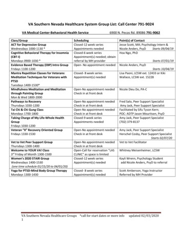
Classification:AT20-001Reference:Date:NTB20-035May 19, 20202018-2019 SENTRA; CVT JUDDER2018-2019 Sentra (B17)APPLIED VEHICLES:MRA8DE (non-turbo engine)APPLIED ENGINE:APPLIED TRANSMISSION: CVT (RE0F11A)IF YOU CONFIRMThe customer reports a transmission judder (shake, shudder, single or multiple bumps orvibration), hesitation on acceleration, lack of power or RPM flare.ACTIONRefer to the Repair Overview on pages 2 and 3.IMPORTANT: The purpose of ACTION (above) is to give you a quick idea of the work youwill be performing. You MUST closely follow the entire SERVICE PROCEDURE as itcontains information that is essential to successfully complete this repair.Nissan Bulletins are intended for use by qualified technicians, not 'do-it-yourselfers'. Qualified technicians areproperly trained individuals who have the equipment, tools, safety instruction, and know-how to do a jobproperly and safely. NOTE: If you believe that a described condition may apply to a particular vehicle, DONOT assume that it does. See your Nissan dealer to determine if this applies to your vehicle.1/147
Repair OverviewThe customer reports a transmission judder (shake,shudder, single or multiple bumps or vibration), hesitationon acceleration, lack of power or RPM flareNoYesAre one or more of the following DTC(s) stored?P0746, P0846, P0868, P0965, P17F0, P17F1, P17F2,P17F3, P17F4, P2857, P2858, P2859, P285ANoYesConfirm the currentTCM part number.Is reprogrammingavailable?Continue tothe next page.NoYesReprogram the TCMfollowing NTB20-037.This bulletin does notapply.Refer to ASIST for furtherdiagnostic information.2/147NTB20-035
Repair Overview (continued)Continued from the previous page.Are one or more of the following DTC(s) stored?P17F2, P17F4, P2857, P2858, P2859, P285AYesNoIs an abnormal CVT noise present?If so, does the noise occur in Park orNeutral, but stops when shifting to Driveor Reverse with the brakes applied?YesNoInspect the CVT pan for excessive debris.Reference Figures 18-22 on pages 14-15.Is excessive debris present?YesReplace the CVT.Refer to CVTAssemblyReplacementApproval Procedureson page 147.NoYesYesIs P17F0 stored?NoDoes the vehicle haveequal to or greater than84 months in service or84,000 miles?NoRemove control valve to allow forCVT belt inspection.Go to Control Valve (ValveBody) Removal on page 12.Is there evidence of CVT beltslippage?YesInspect input shaftbearing condition startingon page 43. Is anabnormality present?YesNoNoPerform Pulse Rotor Inspectionon page 30.YesIs the pulse rotor loose?Replace the belt &pulley, control valveand oil pump(starting on page 32).NoReplace only thecontrol valve (page 32).Print out the DTCs andattach to the repair order.3/147NTB20-035
Table of Contents Required Tools / Material . page 6 Essential Special Service Tools . . .page 6 Weights page 9 Precautions when Disassembling a CVT Assembly page 10 Inspection for Abnormal Noise page 11 Control Valve Removal .page 12 CVT Belt Visual Inspection .page 18 Pulse Rotor Inspection .page 30 No Belt Damage/Pulse Rotor Not Loose – Replace Control Valve .page 32 Belt Damaged Or Pulse Rotor Loose page 33 Remove CVT from Vehicle and Disassemble External Parts .page 33 Remove the Fluid Filter . .page 35 Remove the Oil Pan and Torque Converter Housing . page 37 Remove the Oil Seals from the Torque Converter Housing .page 38 Remove the CVT Internal Components page 39 Remove the Sub-assembly .page 50 Clean the CVT Surfaces . .page 56 Clean Oil Passages in the CVT Case and Oil Pump Cover . . .page 57 Measuring the CVT Sub-assembly Case Depth .page 63 New Snap Ring Selection and Installation to the New Sub-assembly . .page 66 Install Sub-assembly to CVT Case page 72 Install the Oil Pump and the Manual Shaft . .page 77 Install Powertrain Parts . . page 80 Install the Torque Converter Housing page 88 Install the Control Valve and the Oil Pan . . .page 91 Seal the Sub-assembly Cover . .page 944/147NTB20-035
Table of Contents (continued) Install and Adjust the Transmission Range Switch .page 99 Install Exterior CVT Parts. . .page 100 Install the CVT Assembly page 105 Additional Service When Replacing Control Valve or Transaxle Assemblypage 106 TCM Reprogramming. . . page 107 TCM Recovery .page 126 Control Valve Replacement .page 127 Erase Learning Value page 132 Conform CVTF Deteriortn .page 134 Auxiliary Gearbox Clutchpoint Learning .page 137 PARTS INFORMATION page 140 CLAIMS INFORMATION .page 142 KIT PARTS REFERENCE TABLE. . .page 144 CVT Assembly Replacement Approval Procedures .page 147 AMENDMENT HISTORY . page 1475/147NTB20-035
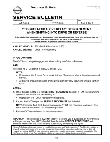
REQUIRED TOOLS / MATERIALS Petroleum jelly or equivalentExtendable magnetLarge clean surface / 1 to 2 work tablesBrake cleanerRubbing alcoholPlastic scraperMalletSandpaperEssential Special Service ToolsAdditional Essential Tools are available from Tech Mate online: www.nissantechmate.comor by phone: 1-800-662-2001.J-52278CVT2 Oil PumpSeal InstallerJ-50255CVT Service Tool KitJ-50272Digital DepthGaugeJ-51923J-Hook CaseSeparatorJ-25721-ASlide Hammer SetJ-50271Gauge BlockJ-8092 or J-52280Driver HandleFigure 1Figure 26/147J-52281CVT Case DifferentialSeal InstallerJ-52272 Assembly GuidePins, Pulley BracketNTB20-035
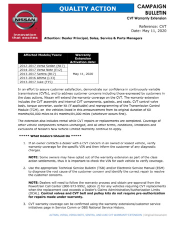
Essential Special Service Tools (continued)Tech Cam J-51951Figure 3J-52306-1 and J-52306-2Transmission Range SwitchAlignment Bracket and PinJ-52273 ClutchEngagement ToolFigure 4Figure 5J-42909 EvapPressure Test KitFigure 67/147NTB20-035
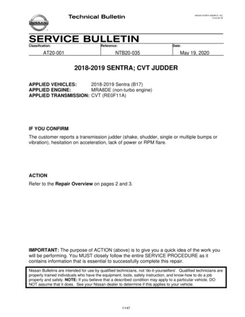
Essential Special Service Tools (continued) Split Ring Seal Installer Kit J-52595J-52595-4Split Ring Seal CoverJ-52595-3Seal DriverFigure 7Figure 8J-52595-1First Groove Seal Tool (Top)J-52595-1First Groove Seal Tool (Bottom)Figure 10Figure 9J-52595-2Second Groove Seal Tool (Bottom)J-52595-2Second Groove Seal Tool (Top)Figure 11Figure 128/147NTB20-035
Essential Special Service Tools (continued)J-52728Pulse Rotor LockFigure 13J-52729-2 WheelLug Torque AdapterFigure 14A.Weights CVT assembly: 150 lbs. approximately CVT sub-assembly: 40 lbs. approximately9/147NTB20-035
SERVICE PROCEDUREIMPORTANT: Repairs performed for this bulletin require CONSULT-III plus (C-III plus)Diagnostic result reporting function-Setting be turned ON and Diagnosis (AllSystems) be performed. If not done, it may result in a repair being non-warrantable.Precautions when Disassembling a CVT AssemblyIMPORTANT:Transmissions are vulnerable to particle contamination (dust, metal, lint, etc.).When disassembling a CVT, make sure your work environment (shop, workbench, etc.),transmission area (sub-frame, oil pan, harness connector, etc.), and your hands are free ofany contamination.It is essential that any foreign contamination be kept out of the CVT internals. Disassemblyand re-assembly shall be carried out under the following conditions:To prevent possible drivability concerns, cover all air breather anddrive shaft holes to prevent water intrusion. Wash and clean the exterior of the CVT assembly prior to disassembling.Work in a covered indoor room to prevent contamination of the CVT.Work on a clean stainless drain table.Avoid debris from dropping into the converter housing, side cover or CVT case.Remove any sealant remaining on bolts or mating surfaces of the converter housing,side cover and/or the CVT case using a scraper, and then clean with lint-free papercloths.Do not use cotton gloves or woven cloths. Latex or rubber gloves are recommended. Use only lint-free paper cloths.Apply rust penetrant to locator / dowel pins on the torque converter housing and sidecover of CVT and allow to soak as needed.Only disassemble those parts which are mentioned in this bulletin.Make sure all parts are clean prior to assembling / installing. Brake cleaner is acceptable to remove remaining CVT fluid and residual sealer. Unpack service parts just before installation.Use only specified sealant material.Parts cups Store the related parts that havebeen removed separately to preventbeing mixed up; small cups can beused.Figure 1510/147NTB20-035
Non-warrantable damage to the CVT may occur if thesteps in this procedure are not followed in order.Inspection for Abnormal NoiseHINT: If DTCs are stored, abnormal noise may be present.Listen for any abnormal CVT noises under the following conditions:Set the parking brake, and start the engine. If an abnormal CVT noise stops once the CVT is shifted into drive or reverse, thisbulletin does not apply. Refer to ASIST for further diagnostic information. If an abnormal CVT noise occurs while the CVT is in Drive (D) or Reverse (R),proceed to Control Valve (Valve Body) Removal on the next page.11/147NTB20-035
Control Valve (Valve Body) Removal To avoid damage to the CVT, never allow any chemicals or fluids other thanNS-3 CVT fluid or suitable cleaners to enter the CVT assembly.To avoid damage to the CVT, never allow any foreign debris, dust, dirt, etc. toenter the CVT assembly.1. Write down all audio presets.PresetsAMFM 1FM 2SAT 1SAT 2/3Bass1Treble23Balance4Fade56Speed Sen. Vol.2. Place the vehicle on a lift.3. Before lifting the vehicle, place the transmission gear selector in Neutral.4. Disconnect both battery cables, negative cable first.5. Raise the vehicle, and then drain the CVT fluid by removing the drain plug. Remove the engine under cover if needed.To avoid the risk of minor personal injury, use caution when looking intothe drain hole as there is the risk of fluid entering the eye.6. Disconnect the engine room harness from the CVT.7. Remove the oil pan mounting bolts, andthen remove the oil pan and oil pangasket. Do not discard the bolts. They will bereused during assembly.Figure 1612/147NTB20-035
Exploded ViewFigure 171. Transaxle assembly4. Manual plate7. Strainer10. Oil pan2. O-ring5. Washer8. Oil pan gasket11. Drain plug gasket3. Control valve6. O-ring9. Magnet12. Drain plug: Always replace after every disassembly.: N m (kg-m, ft-lb): N m (kg-m, in-lb)13/147NTB20-035
8. Inspect the inside of the CVT oil pan for any evidence of broken parts.EXAMPLE: Figure 18 and Figure 19 are acceptable for this repair – Magnets with finedebris or sludge in any amount.OKFine debrisFigure 18Any amount of finedebris is acceptable.OKFine debrisFigure 19Continue to the next page.14/147NTB20-035
Figure 20, Figure 21 and Figure 22 are No Good (NG) for this repair - Brokenparts would include pieces of bearings, clutch material, belt elements, etc.NGBearing rollersor bearing raceFigure 20Large metalpiecesNGFigure 21Bearing seal(green)NGFigure 22Continue to the next page.15/147NTB20-035
Is there any evidence of broken parts or excessive debris?o YES: Replace the CVT assembly as follows:a. Document the debris found with a video (see page 147 for details).b. Reinstall the CVT oil pan gasket and oil pan.c. Call the PCC for CVT replacement authorization (see page 147 for contactinformation).d. Refer to the Electronic Service Manual (ESM), section TRANSMISSION &DRIVELINE TRANSAXLE & TRANSMISSION CVT: RE0F11A UNIT REMOVAL AND INSTALLATION TRANSAXLE ASSEMBLY forCVT replacement.o NO: If DTC P17F0 is not stored, proceed to step 10. If DTC P17F0 is stored, continue to step 9.9. Install the original (removed) CVT oil pan gasket and oil pan temporarily with at leasttwo oil pan bolts, hand tight. Skip to step 30 on page 33.10. Remove the three (3) oil strainer bolts,and then remove the oil strainer from thecontrol valve. 3 boltsThese bolts will be reused.Oil StrainerFigure 2316/147NTB20-035
Nut and washer11. Remove the nut and washer, and thenremove the manual plate shown inFigure 24. Use a screwdriver to hold the manualplate (Figure 25) to keep the shaftfrom rotating while removing the nut. Manual plateDo not discard the nut and washer.These will be reused duringassembly.12. Clean around the CVT unit harnessconnector to prevent foreign materialsfrom entering into the CVT case (picturenot shown).Figure 24Manual plateFigure 2513. Remove ONLY the eleven (11) controlvalve bolts circled in yellow withmarkings as shown in Figure 26. On this model transaxle, Do NOTremove the bolts with a single dotover the “7” (not shown). The bolts removed will be reused.Control valve bolts14. Press the CVT unit harness connectordown into the transaxle case, and thenremove the control valve from thetransaxle case.Figure 26Transaxle damagemay occur if care is not taken whenhandling the CVT unit harnessconnector.17/147Remove boltswith thismarkingNTB20-035
CVT Belt Visual Inspection15. Secure the passenger side (RH) front wheel with a suitable strap.a. Connect the first hook of the strap to the coil spring as shown in Figure 27.b. Route the strap around the center of the tire and attach the second hook through theeyelet of the first hook that is attached to the coil spring.c. Tighten the strap sufficiently to keep the passenger side (RH) front tire from rotatingbut do not overtighten.d. This will assist in making the belt turn during the borescope belt inspection step.Coil springPassengerside (RH)Figure 2716. Mark the driver side (LH) front wheel with a suitable marking. This will ensure all 360 of the belt are inspected.18/147NTB20-035
17. Inspect the entirety of the two sides of the belt that come in contact with the pulleys(Figure 28).IMPORTANT: Reference Figure 40 through Figure 48 on pages 26-29 for comparison. Use borescope J-51951 with mirror attachment. Be sure to remove the protective film from the mirror before the first use. Clean the camera lens and mirror before each inspection. Use 90% isopropylalcohol and a lens swab from Lens Swab packet J-51963 listed in PARTSINFORMATION on page 140. Before inspecting, make sure the batteries in the camera handle and LCD monitorare charged.Inspectthese sidesDo not inspectthese sidesFigure 28a. Install the Clutch Engagement Tool (J-52273) to the CVT case with two bolts, fingertight, where shown in Figure 29 and Figure 30. Bolt torque not to exceed: 2.26 N m (0.23 kg-m, 20 in-lb.) Use care when tightening the bolts as damage to the bolts/CVT could occur. Make sure an O-ring is installed to the Clutch Engagement Tool (J-52273)before installation as this could lead to improper/incomplete testing.19/147NTB20-035
HINT: The O-ring for the Clutch Engagement Tool comes with the attachment. To orderadditional O-rings, refer to PARTS INFORMATION on page 140.BoltsFront ofvehicleClutchengagement tool(J-52273)Clutch packFigure 29Figure 30b. Connect the hand pump from EvapPressure Test Kit (J-42909) to theClutch Engagement Tool (J-52273)and pump to 30 PSI (Figure 31).Hand pumpIMPORTANT: Proper pressure has been achievedwhen the CVT belt moves while thedriver side (LH) front wheel is rotatedand the CVT is in NEUTRAL with thepassenger side (RH) front wheelsecured. The hand pump should be removedfrom the Clutch Engagement Tool(J-52273) quick connect once theclutch has been engaged and thebelt is observed moving with tirerotation. Pressure will be retained.Figure 31Do NOT over-pressurize the system as internal damage to the CVTcould result.20/147NTB20-035
c. Insert the borescope where shown in Figure 32 as follows:i.ii.iii.Face the mirror of the borescope toward the driver side of the vehicle (CVTside cover).Insert the lens approximately 7.5 inches from the CVT oil pan gasket surfaceas shown in Figure 34 on page 22.View the side of the belt that contacts the pulley.Look through here tohelp guide borescopeFront ofvehicleInsert borescopehere at location 1Figure 32DriversideBeltInsert borescopehereFace the mirror in thedirection indicated bythe yellow arrowFigure 3321/147NTB20-035
View point is onopposite side of beltCVT shown removed fromthe vehicle and withoutside cover for clarity, andis for reference onlyFigure 34d. Using the mark applied to the driverside (LH) front wheel for reference,slowly and carefully rotate the driverside (LH) front wheel one full turn ineither direction to view all of the belt. Holding the borescope (cameraflexible tube) with one handallows rotation of the wheel withthe other hand (Figure 35). If evidence of belt slip is identifiedas shown in Figure 44 throughFigure 48 on pages 28-29, skip tostep 26 on page 33. Figure 35If the belt does not move whenrotating the driver side (LH) frontwheel, return to step 17b onpage 20.e. If the inspection result confirms that no slippage has occurred on the observed side,inspect the other side of the belt as follows:22/147NTB20-035
For the following steps, printthis page as a template andthen shape the borescopecamera flexible tube like theimage in Figure 36. Do not shrink orenlarge the sheet sizewhen printing. The template shown isactual size whenprinted on 8.5” x 11”paper.The figure is9 incheslong4 inches15 Camera view: Face themirror in the direction ofthe yellow arrow.Figure 3623/147NTB20-035
i.Face the mirror of the borescope toward passenger side (engine side).ii.Insert the borescope in the second location where shown in Figure 37 andFigure 38.iii.Insert the lens approximately 8.7 inches from the CVT case rim as shown inFigure 39 on page 25.iv.View the side of the belt that contacts the pulley.Front ofvehicleInsert borescope atlocation 2 and also lookthrough here to helpguide borescopeFigure 37PassengersideInsert borescopehereFace the mirror in thedirection indicated bythe yellow arrowBeltFigure 3824/147NTB20-035
Shown removed from thevehicle and without sidecover for clarity, and isfor reference onlyBorescopeBorescope position,inserted from bottomFigure 39f. Using the mark applied to the driver side (LH) front wheel for reference, slowly andcarefully rotate the driver side (LH) front wheel one full turn in either direction to viewall of the belt.i.Holding the borescope (camera flexible tube) with one hand allows rotation ofthe wheel with the other hand (Figure 35).HINT: If the belt does not move when rotating the driver side (LH) front wheel,supply additional air with hand pump (J-45664) to re-engage the clutch asnecessary.ii.Look for evidence of belt slip as shown in Figure 44 through Figure 48 onpages 28 - 29.g. Is the inspection result OK (no evidence of slip) for 360 rotation of both sides of thebelt?YES: Go to step 18 on page 30.NO: Skip to step 26 on page 33.25/147NTB20-035
Figure 40Figure 4126/147NTB20-035
OKVisual linesFigure 42OKVisual linesFigure 4327/147NTB20-035
NGFigure 44NGFigure 4528/147NTB20-035
NGFigure 46NGFigure 47NGFigure 4829/147NTB20-035
Pulse Rotor Inspection18. Check for looseness in the pulse rotor using special tools Pulse Rotor Lock J-52728 andWheel Lug Torque Adapter Set J-52729.Secondaryspeedsensora. Remove the secondary speedsensor. Refer to the ESM, sectionTRANSMISSION & DRIVELINE TRANSAXLE & TRANSMISSION CVT: RE0F11A REMOVAL ANDINSTALLATION SECONDARYSPEED SENSOR. Remove the O-ring from thesecondary speed sensor. The Oring is a one-time use part. Do notreuse.Figure 49b. Install the Pulse Rotor Lock Tool J-52728 into the secondary speed sensor hole andtighten the bolt to 5.9 N m (0.60 kg-m, 52 in-lb.)c. Using the Wheel Lug Torque Adapter Set J-52729-1 and an appropriate torquewrench, apply torque to the driver side (LH) front wheel (Figure 50).d. Smoothly apply a maximum torque of25 N m (2.5 kg-m, 18 ft-lbs) in aforward driving direction (counterclockwise at driver side [LH] frontwheel). A slight movement in the frontwheel is considered normal dueto gear lash.Driver Side (LH)Figure 50e. Was maximum torque 25 N m (2.5 kg-m, 18 ft-lbs) achieved without wheel spin in aforward direction? YES: Continue to step 18f on page 31. NO: Skip to step 18h on page 31.30/147NTB20-035
f. Smoothly apply a maximum torque of25 N m (2.5 kg-m, 18 ft-lbs) in areverse driving direction (Clockwiseto the driver side (LH) front wheel). Driver Side (LH)A slight movement in the frontwheel is considered normal dueto gear lash.Figure 51g. Was maximum torque 25 N m (2.5 kg-m, 18 ft-lbs) achieved without wheel spin ineither direction? YES: Skip to step 19 on page 32. NO: Continue to step 18h.h. If the driver side (LH) front wheel spins in either direction, check the following:i. Ensure the passenger side (RH) front wheel is not moving when applying torqueas referenced in step 18d on page 30 and step 18f on page 31. If the passenger side (RH) front wheel is moving, check that the strap securingthe passenger side (RH) front wheel is secure. If the CVT belt is NOT moving while the wheel spins return to step 17b on page20 and verify the clutch engagement tool is at 30 PSI.If the driver side (LH) front wheel still spins in either direction after checking all of thepossible causes in step 18h, a loose pulse rotor is confirmed. Skip to step 26 onpage 33.31/147NTB20-035
No Belt Damage and Pulse Rotor Not Loose – Replace Control Valve19. Remove the Pulse Rotor Lock Tool J-52728 if previously installed.20. Reinstall the secondary speed sensor if previously removed. Refer to the ESM, section TRANSMISSION & DRIVELINE TRANSAXLE &TRANSMISSION CVT: RE0F11A REMOVAL AND INSTALLATION SECONDARY SPEED SENSOR. The secondary speed sensor O-ring is a one-time use part. Do not reuse.HINT: See Reference # 19 in the KIT PARTS REFERENCE TABLE.21. Remove the Clutch Engagement Tool J-52273 from the CVT.To avoid the risk of minor personal injury, place a rag over the ClutchEngagement tool and SLOWLY loosen the two bolts until the audible depressurization isnoted. The remaining CVT fluid may spray when the Clutch Engagement Tool isremoved.22. Install a new control valve in the reverse order of disassembly: Refer to steps 163 - 174 on pages 91 - 93.23. Connect both battery cables, negative cable last.24. Reset/reinitialize systems as needed. Refer to the ESM, section GENERAL INFORMATION GENERAL INFORMATION BASIC INSPECTION ADDITIONAL SERVICE WHEN REMOVING BATTERYNEGATIVE TERMINAL, for a listing of systems that require reset/initialization afterreconnecting the 12V battery. This list often includes items such as radio, power windows, clock, sunroof, etc.25. Perform Additional Service When Replacing Control Valve or Transaxle Assemblystarting on page 106.32/147NTB20-035
Belt Damaged or Pulse Rotor Loose26. Remove the Pulse Rotor Lock Tool (J-52728) if previously installed.27. Remove the Clutch Engagement Tool (J-52273) from the CVT.To avoid the risk of minor personal injury, place a rag over the ClutchEngagement tool and SLOWLY loosen the two bolts until the audible depressurization isnoted. The remaining CVT fluid may spray when the Clutch Engagement Tool isremoved.28. Install the original (removed) oil pan gasket and oil pan temporarily with at least two oilpan bolts, hand tight.IMPORTANT: DO NOT discard the remaining oil pan bolts. These bolts will be reused.29. Continue to step 30.Remove CVT from the Vehicle and Disassemble External Parts30. Remove the CVT from the vehicle. Refer to the ESM, section TRANSMISSION & DRIVELINE TRANSAXLE &TRANSMISSION CVT: RE0F11A UNIT REMOVAL AND INSTALLATION TRANSAXLE ASSEMBLY.31. Remove the torque converter and setaside. The torque converter may be reusedif CVT replacement is not required.32. Put the CVT assembly on a work benchwith the oil pan side down. Torque converterTo avoid minor personal injury, useassistance when placing the CVT onthe work bench.Figure 52 Use care when placing the CVT onthe work bench to avoid damage tothe oil pan or internal CVTcomponents.33. Drain the CVT fluid out of the torqueconverter.Figure 5333/147NTB20-035
34. Remove the output speed sensor, primary speed sensor and secondary speed sensorfrom the CVT (Figure 54, Figure 55 and Figure 56). These sensors will be reused.Inspect all three sensors for debris on the magnet and clean as necessary.SecondaryspeedsensorPrimary speedsensorFigure 54Figure 55Figure 5635. Remove the O-rings from all three speedsensors. Output speedsensorThe O-rings are one-time use parts.Do not reuse.Figure 5734/147NTB20-035
Remove the Fluid Filter36. Remove the fluid filter from the CVTcase as follows:Fluid filter cover bolta. Remove the fluid filter cover bolt. This bolt will be reused.Fluid filter coverFigure 58b. Rotate the fluid filter covercounterclockwise approximately 15degrees or until the cover clears theside cover tab.Side cover tabc. Pull the fluid filter cover away fromthe CVT case to remove.Figure 5937. Pull the fluid filter with grommet away from the CVT case to remove. The filter is a one-time use part. Do not reuse.NOTE: The grommet may separate from the filter and remain on the CVT case.GrommetOil filterFigure 61Figure 6035/147NTB20-035
38. Remove the O-ring from the fluid filtercover. The O-ring is a one-time use part.Do not reuse.Figure 6239. Thoroughly wipe and clean the inside ofthe fluid filter cover. Brake cleaner may be used duringthis step to thoroughly remove anyresidual material.Figure 6340. Thoroughly wipe and clean the filter boreof the CVT case.Filter boreFigure 6436/147NTB20-035
Remove the Oil Pan and Torque Converter Housing41. Reposition the CVT assembly on thework bench with the torque converterhousing side facing up. Use plastic or wood blocks tostabilize the CVT assembly on thework bench if needed.NOTE: CVT fluid will drain from the CVTcase when the oil pan is removed.Figure 6542. Remove the oil pan and oil pan gasket which were installed to the CVT temporarily.Bolts will be reused. Keep the original oil pan for installation during reassembly.43. Remove the nineteen (19) bolts circled in yellow shown in Figure 66 from the torqueconverter housing. Do not discard these bolts. They will be temporarily re-used later in this procedure.NOTE: The bolts that are not visible in Figure 66 are indicated with a dotted yellowcircle.Torque converterhousingSlide hammer locationfor torque converterhousing removalFigure 6637/147NTB20-035
44. Remove the torque converter housing from the CVT case. If necessary, use a Slide Hammer J-25721-A at the three locations (highlighted ingreen) shown in Figure 66. The input shaft thrust bearing washer may be attached to the torque converterhousing, remove it and put it aside; it will be reused.Remove the Oil Seals from the Torque Converter Housing45. Remove the torque converter oil seal from the torque converter housing with a suitabletool. Take care not to damage the seal-to-case surface when removing seal. The torque converter oil seal is a one-time use part. Do not reuse.46. Remove the differential side oil seal from the torque converter housing with a suitabletool. The differential side oil seal is a one-time use part. Do not reuse.Torque converter housingDifferential sideoil sealTorque converteroil sealFigure 6738/147NTB20-035
Remove the CVT Internal Components47. Remove the final drive assembly and thereduction gear assembly at the sametime by lifting both straight up.Reduction gearassemblyLip sealO-ringFinal driveassemblyFigure 6848. Remove the lip seal from the CVT case. Lip sealThe lip seal is a one-time use part.Do not reuse.Figure 6949. Remove the O-ring from the CVT case. The O-ring is a one-time use part. Donot reuse.O-ringFigure 7039/147NTB20-035
50. Remove the O-ring from the input shaft. The O-ring is a one-time use part. Do not reuse.51. Remove the thrust bearing from the drive sprocket and set aside to reuse during reassembly.NOTE: The thrust washer for the thrust bearing may either be on the drive sprocket ormay have remained with the torque converter housing when it was removed. The thrust washer will be reused later in this procedure.Input shaftO-ringIf present, the thrustwasher would coverthe bearingThrustbearingDrivesprocketFigure 7152. Spread the snap ring shown in Figure 72 and Figure 73 then remove both sprocketsand the chain.Sprocketsand chainSnap ringFigure 73Figure 7240/147NTB20-035
53. Remove the parking rod from the detentplate. Parking rodDetent plateRotate the parking rod vertically toalign the tab on the parking rod(Figure 75) with the slot on the detentplate and then separate from thedetent plate.Figure 74Align tabwith slotDetent plateFigure 75Reversebrake tube54. Remove the two (2) bolts shown inFigure 76, and then remove the reversebrake tube from the CVT. Do not discard. These will be reusedduring assembly.2 BoltsFigure 7641/147NTB20-035
55. Remove the sleeve from the reversebrake tube. The sleeve is a one-time use part. Donot reuse.SleeveFigure 7756. Remove the six (6) bolts shown in Figure78 and then remove the chain cover. Do not discard. The bolts and chaincover will be reused duringassembly.Chain coverFigure 7857. Remove the input shaft assembly andthe oil pump cover (dummy cover) fromthe CVT as a unit. Hold the input shaft assembly by theend, as shown in Figure 79, and pullstraight up to remove.HINT: The dummy cover, shaft andbearing will separate if the input shaft isnot held at the end.Input shaft assemblyand the oil pumpcover (dummy cover)42/147Figure 79NTB20-035
58. Confirm the “type” of bearing used on the end of the input shaft, and then proceed to theindicated step. For type “A” roller bearing proceed to step 59. For type “B” ball bearing skip to step 61 on page 45. For type “C” sealed ball bearing skip to step 61 on page 45.Bearing type AFigure 80Bearing type B and C Type C shown59. Remove the outer race of the rollerbearing from the counter bearing bore ofthe CVT case by hand.Do
Additional Essential Tools are available from Tech Mate online: www.nissantechmate.com or by phone: 1-800-662-2001. Figure 1 Figure 2 J-51923 J-Hook Case Separator J-52281 CVT Case Differential Seal Installer J-25721-A Slide Hammer Set J-52278 CVT2 Oil Pump Seal Installer J-8092 or J-52280 Driver Handle J-5