Transcription
Multilevel Granularity Parallelism Synthesis on FPGAsAlexandros Papakonstantinou1, Yun Liang2, John A. Stratton1, Karthik Gururaj3,Deming Chen1, Wen-Mei W. Hwu1, Jason Cong31Electrical & Computer Eng. Dept., University of Illinois, Urbana-Champaign, IL, USA2Advanced Digital Science Center, Illinois at Singapore, Singapore3Computer Science Dept., University of California, Los-Angeles, CA, USA.1{apapako2,stratton,dchen,w-hwu}@illinois.edu, 2{eric.liang}@adsc.com.sg, 3{karthikg,cong}@cs.ucla.eduAbstract— Recent progress in High-Level Synthesis (HLS)techniques has helped raise the abstraction level of FPGAprogramming. However implementation and performanceevaluation of the HLS-generated RTL, involves lengthy logicsynthesis and physical design flows. Moreover, mapping ofdifferent levels of coarse grained parallelism onto hardwarespatial parallelism affects the final FPGA-based performanceboth in terms of cycles and frequency. Evaluation of the richdesign space through the full implementation flow - startingwith high level source code and ending with routed netlist - isprohibitive in various scientific and computing domains, thushindering the adoption of reconfigurable computing. Thiswork presents a framework for multilevel granularityparallelism exploration with HLS-order of efficiency. Ourframework considers different granularities of parallelism formapping CUDA kernels onto high performance FPGA-basedaccelerators. We leverage resource and clock period models toestimate the impact of multi-granularity parallelism extractionon execution cycles and frequency. The proposed MultilevelGranularity Parallelism Synthesis (ML-GPS) frameworkemploys an efficient design space search heuristic in tandemwith the estimation models as well as design layout informationto derive a performance near-optimal configuration. Ourexperimental results demonstrate that ML-GPS can efficientlyidentify and generate CUDA kernel configurations that cansignificantly outperform previous related tools whereas it canoffer competitive performance compared to software kernelexecution on GPUs at a fraction of the energy cost.Keywords-FPGA; High-Level Sytnthesis; Parallel Computing; Design Space ExplorationI.INTRODUCTIONField Programmable Gate Array (FPGA) devices havebeen receiving increased attention and gaining growingmarket during the past two decades. Some of their keyadvantages include re-programmability (compared toASICs), low power (compared to multicores and GPUs),long-term reliability (i.e. higher MTBF due to lowtemperature operation), real-time execution characteristics(i.e. do not depend on operating systems, caches or othernon-deterministic latency sources) and high spatialparallelism that can be tailored to each application.Nevertheless, they suffer from usability challenges whichconsist of i) complex programming models (i.e. low levelhardware description languages, e.g. VHDL, Verilog) and ii)complex and high-latency synthesis flows. As aconsequence, few beyond hardware design experts adoptFPGA programming in practice.Ongoing developments in the field of high-levelsynthesis (HLS) have led to the emergence of severalindustry [1-3] and academia powered [4,5] tools that cangenerate device-specific RTL descriptions from popularHigh-Level programming Languages (HLLs). Such toolshelp raise the abstraction of the programming model andconstitute a significant improvement in FPGAs’ usability.However, the sequential semantics of traditionalprogramming languages greatly inhibit HLS tools fromextracting parallelism at coarser granularities than instructionlevel parallelism (ILP). Even though parallelizingoptimizations such as loop unrolling may help extractcoarser-granularity parallelism at the loop level [6,7], therich spatial hardware parallelism of FPGAs may not beoptimally utilized, resulting in suboptimal performance.Recent trends of CPU and GPU designs toward coarsergrained parallel architectures (e.g. MultiCores andManyCores) have led to a growing general usage of severalnew programming models [8-11] that explicitly exposecoarse-grained parallelism. Some of these programmingmodels, such as OpenMP, streaming languages, etc., havebeen adopted as programming interfaces for mappingapplication parallelism onto FPGA [12-14]. Moreover, therecently introduced CUDA (Compute Unified DeviceArchitecture) [8] programming model by NVIDIA whichprovides a multi-threaded SPMD model for general purposecomputing on GPUs has been selected as the FPGAprogramming model in the FCUDA framework [15].All of these HLS works take advantage of the abundantspatial parallelism in FPGAs to exploit the inherentapplication parallelism. However, in most cases, applicationparallelism is extracted only from a single level ofgranularity (e.g. loop [13,6,7], stream pipeline [14] orprocedure granularity [15]). Moreover, the impact ofadditional parallelism on frequency is either ignored (onlycycles are reported) or dealt with via worst case synthesisconditions (i.e. target very low frequency). Exposing moreparallelism will improve the number of execution cycles butmay severely affect (more than 10X) the clock period due towire routing and fan-out side effects. Thus, neglectingfrequency may lead to a worse design in terms of bothperformance and area.In this paper, we propose a Multilevel GranularityParallelism Synthesis (ML-GPS) HLS-based framework formapping CUDA kernels onto FPGAs. We leverageparallelism extraction at four different granularity levels: i)array ii) thread, iii) core and iv) core-cluster. By tuningparallelism extraction across different granularities, our goal
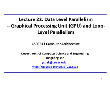
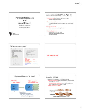
is to find a good balance between execution cycles andfrequency. ML-GPS is based on existing HLS tools andprovides an automated framework for i) considering theeffect of multilevel parallelism extraction on both executioncycles and frequency and ii) leveraging HLL codetransformations (such as unroll-and-jam, procedure callreplication and array partitioning) to guide the HLS tools inmultilevel granularity parallelism synthesis.Exploration of several configurations in the hardwaredesign space is often restricted by the slow synthesis andplace-&-route (P&R) processes. HLS tools have been usedfor evaluating different design points in previous work [6,7].Execution cycles and area estimates from HLS wereacquired without going through logic synthesis of the RTL.Array partitioning was exploited together with loop unrollingto improve compute parallelism and eliminate array accessbottlenecks. Given an unroll factor, all the non dependentarray accesses were partitioned. Such an aggressivepartitioning strategy may severely impact the clock period,though (i.e. array partitioning results in extra address/databusses, address decoding and routing logic for on-chipmemories). In this work, we identify the best array partitiondegree considering both kernel and device characteristicsthrough resource and clock period estimation models.Various resource/frequency estimation models have beenproposed [16-18], but not in conjunction with multigranularity parallelism extraction. In this work, we proposeresource and clock period estimation models that predict theresource and clock period as a function of the degrees ofdifferent parallelism granularities (array, thread, core andcore-cluster). Additionally we incorporate physical layoutinformation into the framework by partitioning the designinto physical layout tiles on the FPGA (each core-cluster isplaced in one physical tile). Our clock period estimationmodel takes into account the design resource usage andlayout on the FPGA and predicts the clock perioddegradation due to wire routing. We combine our resourceand period models with HLS tool execution cycleestimations to eliminate the lengthy synthesis and P&R runsduring design space exploration. To explore the multidimensional design space efficiently, we propose a heuristicwhich leverages our estimation models along with a binarysearch algorithm to prune the design space and minimize thenumber of HLS invocations. Thus the ML-GPS frameworkcan efficiently complete the design space exploration withinminutes (rather than days if synthesis and physicalimplementation were used). More importantly, the designspace point selected by the ML-GPS search is shown toprovide up to 7X of speedup with relation to previous work[15], while achieving near optimal performance.The main contributions in this paper are as follows: We describe an automated multilevel granularityparallelism synthesis framework for mapping CUDAkernels onto FPGAs. We derive accurate resource and clock period estimationmodels. We propose a design space exploration algorithm forfast and near-optimal multi-granularity parallelismsynthesis.II.BACKGROUND AND MOTIVATIONThe ML-GPS framework is based on the FCUDAframework [15] (referred to as SL-GPS hereafter) whichdemonstrates a novel HLS-based flow for mapping coarsegrained parallelism in CUDA kernels onto spatial parallelismon reconfigurable fabric. The SPMD CUDA kernels offer aconcise way for describing work to be done by multiplethreads which are organized in groups called thread-blocks.Each thread-block is executed on a GPU streamingmultiprocessor (SM) which comprises of several streamingprocessors (SP) that execute the individual threads. SL-GPSconverts the CUDA kernel threads into thread-loops whichdescribe the work of CUDA thread-blocks. Each thread-loopis then converted into a custom hardware processing enginereferred to as core, hereafter. Each core executes theiterations (aka threads) within its corresponding thread-loopin a sequential fashion and multiple cores are instantiated onthe FPGA. Thus, coarse grained parallelism is extracted onlyat the granularity of thread-loops (i.e. CUDA thread-blocks).CUDA thread-blocks have properties that enable efficientextraction of application parallelism onto spatial parallelism.First, they execute independently and only synchronizethrough off-chip memory across kernel invocations. In SLGPS this translates to multiple instantiated cores that canexecute in parallel without long inter-core communicationsignals. Second, according to the CUDA programmingmodel, each thread-block is assigned to one GPU SM with aprivate set of on-chip memories and registers. In SL-GPSthis is leveraged by allocating private on-chip BRAMs andregisters to each core, thus, eliminating memory accessbottlenecks from shared memories and high fan-out loadsfrom shared registers.However, exposing parallelism at a single level ofgranularity may result in loss of optimization opportunitiesthat may be inherent in different types and granularities ofparallelism. Finer granularities offer parallelism in a morelight-weight fashion by incorporating less resourcereplication at the expense of extra communication. On theother hand, coarser granularities eliminate part of thecommunication by introducing more redundancy. ML-GPSprovides a framework for flexible parallelism synthesis ofdifferent granularities. In addition to the core granularity, theproposed framework considers the granularities of thread,array and core-cluster. As mentioned earlier, corescorrespond to CUDA thread-blocks and in ML-GPS eachcore is represented by a procedure (which contains thethread-loop). Concurrent procedure calls are utilized to guidethe instantiation of parallel cores by the HLS tool. Threadscorrespond to thread-loop iterations and are parallelized byunrolling the thread-loops. Array access optimization isfacilitated by array partitioning (only for arrays residing inon-chip memories). Finally, core-clusters correspond togroups of cores that share a common data communicationinterface (DCI) and placement constraints. The placementconstraints associated with each core-cluster enforce physicalproximity and short interconnection wires between the intracluster modules. As shown in Fig. 1, the placement of eachcluster is constrained within one physical tile.
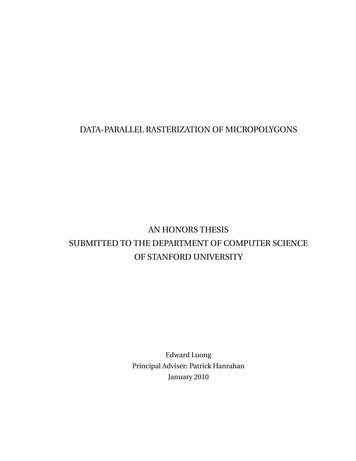
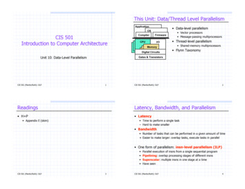
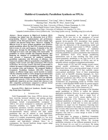
Latency1000100101200320052007200SlicesFigure 2. Design space of mm kernelBoth core- and thread-level parallelism extractionscontribute to compute logic replication. However threads aremore resource efficient (compared to cores) as they allowmore sharing opportunities for memories, registers and otherresource (Fig. 1). The downside of thread-level parallelism islonger and higher fan-out wires between shared resourcesand private logic of each thread as the degree of unrollincreases. Cores on the other hand require fewercommunication paths (only share DCI) at the expense ofhigher logic replication (Fig. 1). At an even finer granularity,array access parallelism is extracted through arraypartitioning and it enables more memory accesses per clockcycle, though at the expense of BRAM resources (eachpartition requires exclusive use of the allocated BRAMs) andaddressing logic.The DCI module includes the logic that carries out thedata transfers to/from the off-chip memories through theDRAM controllers. Sharing a single DCI module among allthe cores on the FPGA may result in long interconnectionwires that severely affect frequency, annulling the benefit ofcore-level parallelism. As a downside, DCI units consumedevice resources while providing no execution uency (MHz)54321025010020080150100500C0 C2 C4 C6 C8 C10a) Execution cyclesML-GPS FRAMEWORK OVERVIEWBefore we introduce the ML-GPS framework, we firstdescribe the corresponding source code transformationsleveraged for the different parallelism granularities weconsider.Thread CountCycles (million)6III.Latency (us)Figure 1. Thread, Core, Core-Cluster and Memory BW granularitiesinterconnection wires by constraining the cluster logicplacement within physical tiles. Moreover, pipelining is usedat the inter-cluster interconnection level (Fig. 1) to connectthe DCI modules with the DRAM controller.The optimal mix of parallelism extraction at differentgranularity levels depends on the application kernelcharacteristics as well as the resource characteristics of theFPGA device. Depending on the application, differentgranularity levels will affect execution cycles, clockfrequency and resource usage in different degrees. Moreover,the absolute and relative capacities of different resourcetypes in the targeted device will determine which granularityof parallelism is more beneficial.Fig. 2 depicts a 2D plot of the design space for the mmkernel in terms of compute latency vs. resource (slices)usage. Each point represents a different configuration (i.e.combination of threads, cores, core-clusters and arraypartition degree). We observe that performance is highlysensitive to the parallelism extraction configurations. Thedepicted design space includes about 300 configurations andtheir evaluation through logic synthesis and P&R took over 7days to complete. The charts in Fig. 3 offer a more detailedview of a small subset of design points in terms of cycles,clock frequency total thread count and latency, respectively.All of the configurations of the depicted subset have highresource utilization (greater than 75% of device slices) andspan a wide range of the design space. The leftmost bar (C0)corresponds to the SL-GPS configuration which leveragesonly core-level parallelism, whereas the other configurationsexploit parallelism in multiple dimensions. In each graph thehighlighted bar corresponds to the best configuration withrespect to the corresponding metric. As we can observe, C8is the configuration with minimum latency, whereas differentconfigurations are optimal in different performance relatedmetrics (i.e. cycles, frequency and thread count). The chartsdemonstrate that i) single granularity parallelism extractiondoes not offer optimal performance and ii) performanceconstituents are impacted differently by different parallelismgranularities.6040200C0 C2 C4 C6 C8 C10C0 C2 C4 C6 C8 C10b) Clock Frequencyc) Hardware concurrencyFigure 3. Performance attributes of mm design space configurations6050403020100SL-GPSC0 C2 C4 C6 C8 C10d) Execution Latency
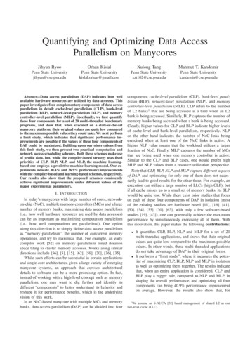
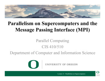
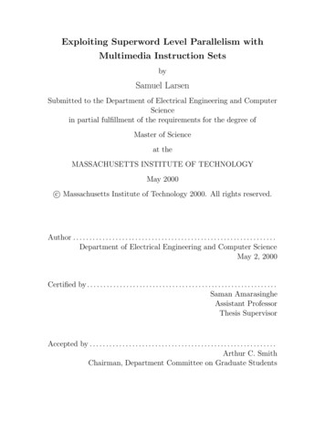
matmul tblock( ) {for(ty 0; ty bDim.y; ty )for(tx 0; tx bDim.x; tx ) {for (k 0; k BLK SIZE; k)Cs[ty][tx] As[ty][k] * Bs[k][tx];}}a) Original mm codematmul tblock( ) {for(ty 0; ty bDim.y/2; ty )for(tx 0; tx bDim.x; tx ) {for (k 0; k BLK SIZE; k)Cs[ty][tx] As[ty][k] * Bs[k][tx];Cs[ty bDim.y/2][tx] As[ty bDim.y/2][k] *Bs[k][tx];}}b) Unrolled thread-loopmatmul tblock( ) {for(ty 0; ty bDim.y/2; ty )for(tx 0; tx bDim.x; tx ) {for (k 0; k BLK SIZE; k)Cs1[ty][tx] As1[ty][k] * Bs[k][tx];Cs2[ty][tx] As2[ty][k] * Bs[k][tx];}}c) Arrays A and C partitionedfor(by 0; by gDim.y/2; by )for(bx 0; bx gDim.x; bx ) {matmul( )matmul( )}d) Thread-block concurrencyFigure 4. Source code transformations (mm kernel)Threads: unfolding of thread-loop iterations throughunroll-and-jam transformations (Fig 4b).Array: on-chip array access concurrency is controlled bythe degree of array partitioning, which divides arrays toseparate partitions (Fig. 4c). Each partition is mapped onto aseparate BRAM and thus, the array acquires multiplememory ports. In this work, array partitioning is applied onlyto arrays with affine accesses [19].Cores: unfolding of threadblock-loop iterations throughreplication of thread-loop function calls (Fig. 4d). Eachfunction call corresponds to the instantiation of one parallelcore.Core-cluster: the set of thread-blocks is partitioned tosubsets, with each subset assigned to one core-cluster.The ML-GPS framework leverages three main engines asdepicted in Fig. 5a: i) a source-to-source transformation(SST) engine ii) a design space exploration (DSE) engineand iii) a HLS engine. The SST engine takes as input theCUDA code along with a set of configuration parametersthat correspond to the degrees of the different parallelismgranularities to be exposed in the output code. Theconfiguration parameters are generated by the DSE enginewhich takes as input the target FPGA device data anddetermines the configurations that should be evaluatedduring the design space exploration. Finally, the HLS enginesynthesizes the generated output code of the SST engine toRTL. In the ML-GPS framework we use a commercial HLStool [2], which generates highly-optimized RTL code.The ML-GPS flow involves three automated main steps(Fig. 5b). Initially a kernel profiling step is performed inorder to build the resource estimation model for each kernel.Profiling entails feeding the SST engine with a small set ofmultilevel granularity configurations which are subsequentlysynthesized by the HLS tool to generate the correspondingresource utilization estimations. A kernel-specific resourcemodel is then built using regression analysis on the HLSresource estimations. The number of the profileda) ML-GPS componentsFigure 5. ML-GPS Overviewb) ML-GPS flowconfiguration points determines the accuracy of the resourceestimation model generated. More configurations result inmore accurate resource models, though, at the expense ofextra profiling time. In the ML-GPS framework the user candetermine the effort spent on profiling.After profiling, the design space is determined in thesecond main step. First the total number of core-clusterconfigurations is determined by considering both theresource estimation model generated in the 1st step (i.e. takeinto account the kernel characteristics) and the selectedFPGA device (i.e. take into account the resource availabilityand distribution on the device). Subsequently the thread,array partitioning and core dimensions of the design spaceare determined for each core-cluster configuration with thehelp of the resource estimation model.Finally in the third main step, design space exploration isperformed using the resource and the clock period estimationmodels along with cycle estimates from the HLS tool toevaluate the performance of the different design points. Abinary search heuristic is used to trim down the number ofHLS invocations and prune the design space. The DSEengine’s goal is to identify the optimal coordinates in themulti-dimensional parallelism granularity space in order tomaximize the performance of the CUDA kernel on theselected FPGA device (i.e. given a fixed resource budget).IV.DESIGN SPACE EXPLORATIONAs mentioned previously, exploration of the multilevelgranularity space is based on estimations of resource, clockperiod and cycles. We estimate resource and clock perioddegradation due to routing through regression analysis basedequations, whereas we leverage cycle estimations from HLS.The formulas used for resource and clock period estimationsare presented in the following section. To optimize the spaceexploration runtime we employ an efficient searchoptimization that helps minimize the number of HLS toolinvocations during the search process. This is discussed inSection IV.B.A. Resource and Clock Period Estimation ModelsThe resource model is built during the profiling step ofthe flow. A small number of points in the design space areused to generate different configurations of the input kernelexposing different granularities of parallelism. The HLS toolis fed with the profiled kernel configurations and it returnsresource estimation results. We classify the resourceestimations based on the degrees of parallelism exposed atthe core (CR), thread (TH), and array-partitioning (AP)dimensions. Using linear regression we then evaluate the R0,R1, R2 R3 and R4 coefficients of (1):
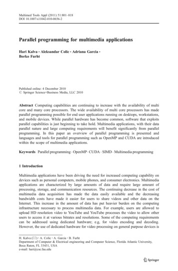
2Diag is calculated using (3) and it corresponds to thediagonal length (in slices) of a virtual tile with the followingproperties: i) the total core-cluster slices can fit in the virtualtile, ii) the dimensions of the virtual tile do not exceed thedimensions of the allocated physical tile and iii) the diagonallength of the virtual tile is minimal given the two previousconstraints. Util in (2) represents the slice utilization rate ofthe physical tile by the core-cluster logic.2,,3where minDim corresponds to the minimum dimensionof the physical tile (in slices) and Rslice is the slice count ofthe core-cluster logic. Parameters Rslice (hence Diag) and Utilin (2) are calculated by leveraging the resource modeldescribed above. Conceptually, parameter Diag incorporatesthe core-cluster resource area and layout information whileUtil incorporates the routing flexibility into the periodmodel. AP and TH represent the requirement for extra wireconnectivity within each core due to array partitioning andthread-loop unrolling.B. Design Space Search Algorithm1) Latency EstimationFollowing the resource model construction for eachkernel, the multi-dimensional design space can be boundgiven a resource constraint, i.e. an FPGA device target. Our,,,4where Nblock represents the total number of kernel threadblocks, Cyc is the number of execution cycles required forone thread-block and Period is the clock period. As wasdiscussed earlier, Period is affected by all the design spacedimensions and is estimated through our estimation model in(2). On the other hand, Cyc is generated by the HLS engineand is only affected by the TH and AP dimensions (i.e. theHLS engine’s scheduling depends on the thread-loopunrolling and array partitioning degrees). Thus for the designsubspace that corresponds to a pair of unroll (u) and arraypartitioning (m) degrees, Lat is minimized when theexpression in (5) is minimized. We leverage this observationin tandem with our binary search heuristic to prune thedesign space and cut down the HLS invocations.,,,52) Binary Search HeuristicThe binary search heuristic is guided by the followingobservation:Observation 1: For a given loop unroll factor, latencydecreases monotonically first with a subsequent monotonicincrease as the array partition degree increases.Fig. 6a depicts the fwt2 kernel latency for different unrolland array-partition pairs (u, m). For each point in Fig. 6a, itslatency is determined by using the core () and core) values that minimize E in (5), and thuscluster (minimize Lat. We can observe (Fig. 6a) that the value ofexecution latency as a function of array partition degree for afixed unroll factor decreases monotonically until a globaloptimal point, after which it increases monotonically.Intuitively, as the array partition degree increases, on-chiparray access bandwidth is improved as more array references4Latency (ms)Conceptually, the model characterizes the resource usageof a core-cluster based on the core number (R1), count ofthreads (R2), array partitioning (R3), and the interactionbetween unrolling and array partitioning (R4). For each typeof resource (LUT, Flip-Flop, BRAM and DSP) we constructa separate equation which represents the core-clusterresource usage as a function of the different parallelismgranularities. These equations are kernel-specific and areused during the design space exploration phase for resourcebudgeting as well as for estimating the clock period. Thetotal resource count, RFPGA, is equal to the product of thecore-cluster resource estimation, R, and the number ofphysical tiles, CL, (i.e. number of core-clusters): RFPGA R CL.The clock period model aims to capture the clock perioddegradation resulting from wire routing within the corecluster. The HLS-generated RTL is pipelined for a nominalclock period defined by the user. However the actual clockperiod of the placed netlist is often degraded (i.e. lengthened)due to interconnection wire delays introduced during P&R.Through this model we incorporate the effect of differentparallelism granularities as well as layout information oninterconnection wires (i.e. wires within the core cluster;inter-cluster wires are pipelined appropriately, as mentionedearlier) and thus the clock period. The period estimationmodel is described by (2) which is pre-fitted offline usingsynthesis data (synthesized CUDA kernels were used for theperiod estimation model construction):goal is to identify the configuration with the minimumlatency, Lat, within the bound design space. Latency is afunction of all the parallelism granularity dimensions (i.e.thread (TH), array partitioning (AP), core (CR) and corecluster (CL)) of the space we consider and is estimated using(4):unroll-4unroll-8unroll-163210124Array partition degreea)Latency (ms)121.81.61.41.214111b)82244816Unroll FactorFigure 6. Unroll and Array partition effects on latency
Algorithm 1. Binary Search1 /* search sequence: unroll followed by array partition */;2 Search (1);3 Search (dim)4if search all the dimensions then5Let ( , ) be unroll and array partition pair.6, ,,;7UpdateLatency ( , , );8return;9Let space[] be the design space of dimension dim ;10low 1; high Space ;11 while low high do12mid (low high) / 2;13Select(dim, mid);14res mid Search(dim 1);15Select(dim, mid 1);16res midPlus Search(dim 1);17if res mid res midPlus then18high mid - 1; /* search left */19Update(cur best, res mid);20else21low mid 2; /* search right */22Update(cur best, res midPlus);23return cur bestcan take place concurrently (i.e. execution cycles decrease).However, after a certain degree (saturation point), anyfurther partitioning does not decrease clock cycles.Additionally it hurts frequency due to increased wireconnectivity and higher logic complexity. More importantly,further partitioning may constrain coarse granularityextraction at the core and core-cluster levels as moreBRAMS are used by each core. Thus, there exists an optimalarray partition degree for each unroll factor. Observation 1has been verified for other benchmarks as well.A similar trend has also been observed for unroll factor(Fig. 6b). For each unroll factor u in Fig. 6b, its latency isdetermined by using its optimal array partition degree mfrom Fig. 6a and core () and core-cluster ()values. Intuitively, as the unroll factor increases, moreparallelism is exploited, thus improving the executionlatency. However, unrolling beyond a certain degree may notbe beneficial due to array access bottleneck and frequencydegradation (from increased connectivity and fan-out issues).In summary, there is an optimal unrolling degree.Based on the above observation and the intuition behindit, in Algorithm 1 we propose a binary search algorithm tofind the optimal point (unroll factor u and array partitiondegree m). As shown in Algorithm 1, we search unroll factorfirst followed by array partition degree. Array space[] storesthe feasible values for each dimension dim, in sorted order(line 9). The size and value of space[] are obtained from theresource model. Then, we perform binary search fordimension dim. In each round of the binary search (line 1122), we compare the performance of two middle neighboringpoints (mid, mid 1). Function Select records the valueselected for the dimension dim. The comparison result guidesthe search towards one direction (the direction with smallerlatency) while the other direction is pruned away. In the endof the search across each dimension, the best result of thecurrent dimension (in terms of execution latency) is returned.For each point visited during the search (i.e. (u, m) pair), thecorresponding execution latency is computed based on (4)(line 6). The function UpdateLatency compares the currentsolution with the global best solution and updates it if thecurrent solution turns out to be better.Let us consider fwt2, shown in Fig 6, as an example. Westart searching the unroll degree dimension and compare twoneighboring points in the middle (2 and 4). For each unrollfactor (2 and 4), its minimal latency is returned byrecursively searching next dimension in a binary searchfashion. The best solution so far is stored and the latencycomparison of unroll factors (2 and 4) will indicate thesubsequent search direction. The complexity of our binarysearch is log U log M , where U and M represent the designdimensions of thread and array partition.V.EXPERIMENTAL RESULTSThe goals of our experimental study are threefold: i) toevaluate the effectiveness of the estimation models and thesearch algorithm employed in
spatial parallelism in FPGAs to exploit the inherent application parallelism. However, in most cases, application parallelism is extracted only from a single level of granularity (e.g. loop [13,6,7], stream pipeline [14] or procedure granularity [15]). Moreover, the impact of additional parallelism on frequency is either ignored (only