Transcription
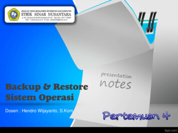
Ghost Image Reduction in Lens Systems with NanoStructured AR-Coatings Using CODE V, RSoft andLightTools 2019 Synopsys, Inc.1CODE V LightTools RSoft
Outline Overview Initial Design, Image Simulation and Ghost Image Analysis Simulation of Diffraction for Detector Micro-Structure Monte Carlo Simulation of Ghost and Flare Subwavelength Nanostructured AR-Coatings Ghost Image Reduction with Subwavelength Structures Optimization of the Subwavelength Structure Conclusion 2019 Synopsys, Inc.2Ghost Image Reduction by NanostructuresCODE V LightTools RSoft
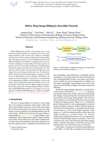
Overview The analysis and control of stray light, composed of ghost images and flare, is an important but complextask for the design of imaging systems Ghost images arise from multiple reflections off of surfaces in the primary optical path– Of specific concern are ghost images that impinge on theimage plane at or near a focus Flare can arise from light reflecting off of lens mounts, nonoptical surfaces of the lenses (such as flats and edges),and as a reflection off of the detector itself reimaged backonto the detector– Modelling light reflected off of the detector can be complicatedby diffraction from the microstructure of the detector In this application note, we will discuss variouscomputational approaches to simulating stray light in animaging lens– All computation was done with Synopsys software, specificallyCODE V, RSoft Device Tools, and LightTools 2019 Synopsys, Inc.3Ghost images in a cell phone camera imageGhost Image Reduction by NanostructuresCODE V LightTools RSoft
Ghost Images Ghost images arise fromreflections off of two surfaces inthe primary optical pathReflectionPrimary ImagePrimary Image– Can include a reflection from thedetector itself Light is then re-imaged backonto the image plane– If that light is near focus, thenthe resulting ghost image can besubstantial Ghost images can typically beanalyzed by sequential raytracing software since thesurfaces involved are from themain imaging path 2019 Synopsys, Inc.4Example 2Example 1Ghost ImagesGhost ImageGhost Image Reduction by NanostructuresCODE V LightTools RSoft
Flare from Non-Optical Surfaces Stray light can also arise from reflection or scattering off of non-optical pathsurfaces or simply passing through surfaces which are not part of thedesigned optical path–Referred to in this talk as ‘flare’ Possible surfaces thatmay give rise to flare:–Mount surfaces or baffling–Edge surfaces of lenses–Lens flats–Reflection off of the detectoror off of surfacessurrounding the detector 2019 Synopsys, Inc.5Flare from reflection off of a mount surfaceGhost Image Reduction by NanostructuresCODE V LightTools RSoft
Reflection off the Detector Structure The detector itself will reflect aportion of the incident light back intothe lens This reflected light can, in turn, bescattered or reflected back on to thedetector, causing ghost images orflare For solid-state detectors such asCMOS chips, the micro-structure ofthe detector can lead to significantdiffraction patterns in the reflectedlight which may have an effect onthe returning stray light patternDetectorPrimary ImageReflectionFlare 2019 Synopsys, Inc.6Ghost Image Reduction by NanostructuresCODE V LightTools RSoft
Stray Light Workflow Shown below is a typical workflow for the analysis of stray light in a camera system when usingSynopsys softwareCODE VLightTools Design the lens to meetoptical performancerequirements Import the lens file fromCODE V Perform a ghost analysisto look for particularlydifficult surface pairs Assign the opticalproperties to the surfacesof the mount, lens anddetector If needed, re-optimizeusing @GHOST to controlghost images Export to LightTools formount design and flareanalysis 2019 Synopsys, Inc.7 Design the lens mount Insert a source Run multiple Monte-Carlosimulations to analyzeflare and ghost imagesGhost Image Reduction by NanostructuresRSoft Model the detector chipand nanostructured ARcoatings in RSoft CAD Use the BSDF Utility tomodel the transmitted andreflected light of thestructure using eitherFullWAVE or DifractMOD Export the BSDF file toLightToolsCODE V LightTools RSoft
Outline Overview Initial Design, Image Simulation and Ghost Image Analysis Simulation of Diffraction for Detector Micro-Structure Monte Carlo Simulation of Ghost and Flare Subwavelength Nanostructured AR-Coatings Ghost Image Reduction with Subwavelength Structures Optimization of the Subwavelength Structure Conclusion 2019 Synopsys, Inc.8Ghost Image Reduction by NanostructuresCODE V LightTools RSoft
CODE V Stray Light Capabilities CODE V is a sequential ray trace code finely tuned for the design, optimization and analysis of imagingsystems While CODE V does not have the ability to analyze flare which originates from non-imaging surfaces itdoes have three very powerful tools for analyzing ghost images– Ghost (GHO) analysis– ghost view.seq macro– @GHOST function The first two features provide critical data in tabularand visual form on ghost images– The analysis is fast and allows the user to easily isolatetroublesome pairs of surfaces for further analysis oroptimization control The @GHOST function allows users to control forghost image disk size during an optimization run– User specifies a surface pair to control 2019 Synopsys, Inc.9Ghost Image Reduction by NanostructuresCODE V LightTools RSoft
Lens Model For the purposes of illustrating the analysis of stray light we will use a moderately wide anglelens for a ½” CMOS detector– Number of Elements: 6– Focal Length: 6.4mm– Aperture: F/3.5– FOV: 32o half-field at the corners– OAL: 27.75mm– Max Distortion: 0.41% (full field)– Relative Illumination: 74% (full field)– MTF: 25% @ 100 cycles/mm– Design Wavelengths: 656nm, 589nm,434nm– Detector Size: 6.4mm x 4.8mm (1/2”Active Pixel Sensor CMOS)– Detector Pixels: 1280 x 960 (5mm x5mm) 2019 Synopsys, Inc.10StopElements 1 – 6: LensesElement 7: Cover PlateElement 8: CMOS DetectorGhost Image Reduction by NanostructuresCODE V LightTools RSoft
Critical Performance MeasuresMTFRay Aberration CurvesDistortionTANGENTIAL1.00RELATIVEFIELD HEIGHT0.025( 32.00 )O-0.0250.71RELATIVEFIELD HEIGHT( 24.00 )O-0.0250.46RELATIVEFIELD HEIGHT( 16.00 )O-0.0250.00RELATIVEFIELD HEIGHT( 0.000 )O-0.02518:23:18MILLIMETERS)06-Dec-16Relative IlluminanceGhost Image Reduction by Nanostructures0.025-0.025CMOS Camera Lens110.025-0.0250.025 2019 Synopsys, Inc.0.025-0.0250.025ORA0.025-0.0250.025RAY ABERRATIONS (SAGITTALCODE V LightTools RSoft 656.0000 NM589.0000 NM434.0000 NM
Ghost Image Analysis The GHO option to lists image properties fordouble-reflections off of all surface paircombinations within the specified range– Data for GHO (and @GHOST) based on a firstorder analysis for the on-axis field so accuracymay be limited for highly aspheric or off-axissystems Information listed include:– Surface Pair creating the reflection– Delta Back Focal Length (DBFL): Distance of the ghost image focus from the real image plane. Values near zeroindicate a ghost image that focuses near the image plane– Effective Focal Length (EFL): This focal length value allows you to compute the size of the ghost image– Disc Semi-Diameter (DISC): Semi-diameter of the reflected beam at the real image plane– Pupil Ratio: Size of the ghost pupil to the stop. Values greater than 1 indicate that the ghost will be attenuated bythe stop– Magnification: The size of the ghost image at its focal plane to that of the real image at the real image plane 2019 Synopsys, Inc.12Ghost Image Reduction by NanostructuresCODE V LightTools RSoft
@GHOST: The @GHOST function allows access to any of the quantities computed by theGHO option (two reflection ghost image)–This analysis is for the paraxial, on-axis field only Can be used to define a User Constraint in optimization to control the size ofthe ghost image from a specified surface pair The @GHOST function is very fast and easy to set up in AUT with goodaccuracy for spherical optics of moderate f/#s The principal drawback to using this option is that it is based on a paraxial raytrace on axis–This means that it can loose accuracy (sometimes quickly) for non-sphericalsurfaces or fast optics 2019 Synopsys, Inc.13Ghost Image Reduction by NanostructuresCODE V LightTools RSoft
Ghost View Macro The Ghost View macro provides avisual representation for all ghost imagesurface pairs in the mode, allowing theuser to quickly visualize the ghostimage pairs The macro converts the lens into a nonsequential surface range allowing therays to pass through the systemmultiple times Based on real ray trace data so it isaccurate for off-axis and asphericsystems 2019 Synopsys, Inc.14Ghost Image Reduction by NanostructuresCODE V LightTools RSoft
GHO, Ghost View example In this example we see a ghostreflection pair of that might be ofsome concern– Reflection pair of surface 5 andsurface 1Real Image– Note the small DBFL value indicatingthat the ghost image focus is verynear the real image plane– Because of this, the DSC disc size isvery small– On the positive size, the PupilMagnification is significantly largerthan 1 ( 3.5 in this case) indicatingthat the ghost image is significantlyvignettedReflective Surface Pair 2019 Synopsys, Inc.15Ghost Image Reduction by NanostructuresGhost ImageCODE V LightTools RSoft
Ghost View Output Examples at 10 Degrees Below are some examples of ghost reflections from a field angle of 10o 2019 Synopsys, Inc.16Ghost Image Reduction by NanostructuresCODE V LightTools RSoft
Including the Image Plane The detector itself can be a source of ghost images and is usually the main source of concern– Light reflecting off of the detector structure can be returned to the detector by lens surfaces– Reflectivity off of a detector is often much higher than a coated optical surface, in our case a full 36%reflectivity Only models the specular reflection and not any scattering off of the detector structureNote that this surface combination,Surface 17 (detector) - Surface 12,is going to be of particular concern 2019 Synopsys, Inc.17Ghost Image Reduction by NanostructuresCODE V LightTools RSoft
Outline Overview Initial Design, Image Simulation and Ghost Image Analysis Simulation of Diffraction for Detector Micro-Structure Monte Carlo Simulation of Ghost and Flare Subwavelength Nanostructured AR-Coatings Ghost Image Reduction with Subwavelength Structures Optimization of the Subwavelength Structure Conclusion 2019 Synopsys, Inc.18Ghost Image Reduction by NanostructuresCODE V LightTools RSoft
Simulating the Reflection Off the Detector One of the main concerns in stray light analysis for cameras that use solid state detectors isreflection off the detector surface itself– Light reflects off the detector structure and returns to the detector by a second reflection off anothersurface While the surface can be modeled as a specular reflector in CODE V or as a simple scatteringsurface using a native LightTools optical property, neither of these are an accuraterepresentation of the reflected light The small scale of the detector structure creates diffraction patterns that cannot be accuratelymodeled using ray tracing alone By using either FullWAVE or BeamPROP, we can accurately model the pattern of reflectedlight from the detector structure and then export that information as a Bi-Directional ScatterDistribution Function (BSDF) file that LightTools can use with its ray trace– Makes use of the RSoft BSDF Utility 2019 Synopsys, Inc.19Ghost Image Reduction by NanostructuresCODE V LightTools RSoft
Combination of RSoft and CODE V-LightTools RSoft Component Tools LightTools and CODE V– Based on physical optics– Based on geometrical optics– Maxwell’s equations, etc.– Snell’s law, etc.– Small photonics devices– Large bulk optical system– Wave propagation and multi-physics– Ray tracing and beam propagation– Diffraction, polarization, nonlinearity,electro-optical, thermo-optics, etc.– Reflection, refraction, diffraction 10lPhysical opticsFullWAVESmaller Geometrical opticsDiffractMODFeature Size vs. WavelengthLarger ( 10 l)The RSoft-CODE V interface and BSDF RSoft-LightTools interface allow users to combine RSoftand CODE V and LightTools to design a large image or display system with nanostructures 2019 Synopsys, Inc.20Ghost Image Reduction by NanostructuresCODE V LightTools RSoft
LightTools BSDF Interface BSDF files contain information about how asurface or structure scatters light (bothreflection and transmission) Scatter information is stored as a function ofangles, wavelength, and polarization BSDF data for both the thin film stack and thepatterned surface can be calculated byFullWAVE or DiffractMODPeriodic Nano-structureBSDFSurface Simulations results are needed at a range ofinput angles, wavelength, and polarization Reflection and transmission results arecombined into single BSDF file This file is then exported to LightTools andapplied as a surface property 2019 Synopsys, Inc.21Light incident onBSDF surfaceGhost Image Reduction by NanostructuresScattering fromBSDF surfaceCODE V LightTools RSoft
LightTools BSDF Interface To automate the process, the RSoft tools feature the BSDF Utility, which automates the BSDFcalculation over a range of incident angles, wavelengths and/or polarization A viewer is available to visualize the BSDF results before they are exported to LightTools 2019 Synopsys, Inc.22Ghost Image Reduction by NanostructuresCODE V LightTools RSoft
CMOS Image SensorGeometry and materials Simplified version of a real device, with 4sub-cells, 1 blue, 1 red and 2 green 2019 Synopsys, Inc.23 Material properties of color filters are fittedbased on transmission spectrum ofFujifilm’s COLOR MOSAICGhost Image Reduction by NanostructuresCODE V LightTools RSoft
Comparing FullWAVE with DiffractMOD FullWAVE DiffractMOD– 5.2G RAM and 32 minutes on 16-cores– 1.6G RAM and 1.5 minutes on 16-cores5 hours on 1-core3.8 minutes on 1-coreDiffractMOD is more efficient, especially for BSDF calculation with many simulations 2019 Synopsys, Inc.24Ghost Image Reduction by NanostructuresCODE V LightTools RSoft
Reflected Diffraction Pattern by Wavelength Here we see reflected intensity results expressed in terms of diffraction orders for threedifferent wavelengthsBlue 2019 Synopsys, Inc.25GreenGhost Image Reduction by NanostructuresRedCODE V LightTools RSoft
Reflected Diffraction Pattern Shown in LightTools Here we see the reflected intensity pattern from the CMOS chip at 550nm as seen inLightTools for various input cone angles The charts are scaled independently in order to see the results more clearly 2019 Synopsys, Inc.26Ghost Image Reduction by NanostructuresCODE V LightTools RSoft
Outline Overview Initial Design, Image Simulation and Ghost Image Analysis Simulation of Diffraction for Detector Micro-Structure Monte Carlo Simulation of Ghost and Flare Subwavelength Nanostructured AR-Coatings Ghost Image Reduction with Subwavelength Structures Optimization of the Subwavelength Structure Conclusion 2019 Synopsys, Inc.27Ghost Image Reduction by NanostructuresCODE V LightTools RSoft
LightTools Stray Light Capabilities LightTools is a non-sequential ray trace code intended for the design, optimization andanalysis of illumination systems Users can easily add lens mounts and other structural elements to the lens model byconstructing them directly or by importing them from CAD LightTools uses a Monte Carlo ray trace approach to simulation the flow of light– Millions of rays can be traced through the lens and the results are collected on the detector(s)– Optical properties can be set to split light at ray surfaces so that reflected and transmitted light can bemodeled The results generally take more time to simulate that in CODE V and are more complex toanalyze For this purpose, LightTools features several primary tools for analyzing stray light– Region analysis– Ray Path and Ray Path Analyzer– Receiver filters 2019 Synopsys, Inc.28Ghost Image Reduction by NanostructuresCODE V LightTools RSoft
Importing the Lens from CODE V For our example, the lens system was imported from CODE V into LightTools using CODE V’sLightTools Export feature The exported lenses were sized according to the edge or clear apertures defined in CODE V Lens sizes were then adjusted in LightTools to match physical part sizesCODE VLightTools 2019 Synopsys, Inc.29Ghost Image Reduction by NanostructuresCODE V LightTools RSoft
Lens Mount The lens mount was created in two parts using native LightTools geometry–It would also be possible to import this mount hardware from a CAD packageFront MountRear Mount 2019 Synopsys, Inc.30Ghost Image Reduction by NanostructuresCODE V LightTools RSoft
M12 Detector Casing A M12 mount with a detector casing, detectorand cover plate were also added to the modelM12 Mount 2019 Synopsys, Inc.31Ghost Image Reduction by NanostructuresCODE V LightTools RSoft
Optical Property Definitions All lens optical surfaces and the cover glass surfaces were defined to have a single layer ARcoating (default) and are set to split the rays–Lens, IR Filter and Cover Glass edge surfaces were defined to have a 5o Gaussianscattering surface with Fresnel reflectivity Mechanical surfaces (mount and spacers) were defined using the LightTools CompleteScatterer– 5% Reflectivity– Of the reflected light, 30% is diffuse (Lambertian)– 70% is Gaussian scattering with a standard deviation of 15o (half-width)– This is an arbitrary surface finish for the purposes of demonstration, using a measured BSDF opticalproperty would be preferred for a real system analysis The front surface of the detector were set to use the BSDF data generated using DiffractMOD– The BSDF file has 36% reflectivity at normal incidence and 550nm A collimated source at 550nm was used to illuminate the system 2019 Synopsys, Inc.32Ghost Image Reduction by NanostructuresCODE V LightTools RSoft
CMOS Reflection Effect The structure of the CMOS chip can have a significant impact on the stray light detected– This is especially true if care is not taken to properly coat the cover plate because of the cover plate’sproximity to the detector– Here we see a comparison of a detector with a specular reflection, one with the BSDF result fromRSoft, and one with the BSDF but no cover plate reflection– Reflectivity values are approximately the same in all three casesSpecular 2019 Synopsys, Inc.33CMOS BSDFGhost Image Reduction by NanostructuresBSDF No Cover PlateCODE V LightTools RSoft
Ray Path Analysis Ray Path is the primary tool for analyzing stray light inLightTools Ray Path can record each ray’s paths– Record paths start at source then pass through surfaces andzones Each path include– Sequential surfaces and zones– Number of ray– Power Ray Path filter can filter “path” on receiver– Filters the rays based on membership in an enabled path Rays can be sorted by power (either in ascending or descending order) so that the most energetic pathsare listed at the top– Useful for quickly finding the most important paths since the catalog lists paths in the order that they werediscovered 2019 Synopsys, Inc.34Ghost Image Reduction by NanostructuresCODE V LightTools RSoft
Ray Path Analysis cont.Full RaySinglerayPathpathcatalogshownshownin 3D Viewin 3D View 2019 Synopsys, Inc.35Image on detector with ray path filter appliedGhost Image Reduction by NanostructuresCODE V LightTools RSoft
Stray Light at 10o Here we see the image produced with the source at 10o The image is shown on a linear scale with the main image over exposedPrimary Image(overexposed)Flare halo fromthe cover plateDominant GhostImage 2019 Synopsys, Inc.36Ghost Image Reduction by NanostructuresCODE V LightTools RSoft
Effect of the Cover Plate Much of the large area stray light seen around the primary image is due to the wide-anglereflection from the detector reflecting back off of the two flat, coated surfaces of the cover platewhich are in close proximity to the detector The single layer MgF2 coating on these flatsurfaces gives a 1.33% reflectivity at normalincidence– This, coupled with the 36% reflectivity of thedetector is much too high By upgrading the coating on the cover plate toreflect 0.2% we can achieve a substantialreduction in the halo 2019 Synopsys, Inc.37Ghost Image Reduction by NanostructuresCODE V LightTools RSoft
Identifying the Dominant Ghost Image The source of the single, dominant ghost image in the field can be identified using Ray Pathand Ray Path Analyzer LightTools confirms the CODE V GHO result that the Detector-Surface 12 pair is the cause ofthe dominant ghost imageSurface 12Primary Image LocationGhost Image 2019 Synopsys, Inc.38Ghost Image Reduction by NanostructuresCODE V LightTools RSoft
Outline Overview Initial Design, Image Simulation and Ghost Image Analysis Simulation of Diffraction for Detector Micro-Structure Monte Carlo Simulation of Ghost and Flare Subwavelength Nanostructured AR-Coatings Ghost Image Reduction with Subwavelength Structures Optimization of the Subwavelength Structure Conclusion 2019 Synopsys, Inc.39Ghost Image Reduction by NanostructuresCODE V LightTools RSoft
Anti-Reflection Coatings Nano arrays Think Film– Simple, but dependent on wavelength,polarization, and incident angle– Complex, but broad band and insensitive topolarization and incident angleCai, Jinguang, and Limin Qi. "Recent advances in antireflective surfacesbased on nanostructure arrays." Materials Horizons 2.1 (2015): 37-53. 2019 Synopsys, Inc.40Ghost Image Reduction by NanostructuresCODE V LightTools RSoft
Subwavelength structure Subwavelength nano-structure can be used to reduce the reflectivity of a surface– In a similar manner, such structures are used to maximize the extraction of LEDs Subwavelength periodic nano-cones or pyramids behaves like a medium with graded index Theoretically, there will be no reflection off a medium with graded index at any wavelengthand at any incident angleNano-conesGraded-indexYn[1]Ou, Qing‐Dong, et al., Advanced Optical Materials 3.1 (2015): 87-94. 2019 Synopsys, Inc.41Ghost Image Reduction by NanostructuresCODE V LightTools RSoft
Improvement of Angular Transmissionand Angular UniformitySub-wavelength conesIndex profileTransmission &Reflection Sub-wavelength cone indeed behaves like a gradedindex structureComparison It could potentially improve the OLED performance 2019 Synopsys, Inc.42Ghost Image Reduction by NanostructuresCODE V LightTools RSoft
Diffraction of Periodic Arrays Periodic gratings diffract light intodifferent orders, in addition to refraction(0-th order)lΛ 𝑠𝑖𝑛α 𝑠𝑖𝑛 𝑚 𝑚𝑛– Where α is the incident angleReflection2nd order1st order0th order– m is diffraction order-1st order– m is diffraction angle– n is the refractive index of the medium For normal incident (α 0), 1st order:l 1 𝑠𝑖𝑛 1𝑛Λ– subwavelength grating Λ diffraction! 2019 Synopsys, Inc.43l𝑛has noTransmission-2nd orderΛn1Ghost Image Reduction by Nanostructures m-1st order-2nd order-3rd order-4th ordern2CODE V LightTools RSoft
Behavior of Nano-StructureFront incidentΛ 2lΛ lΛ l/2 air airΛ sub sub(1) Lower index medium diffracts light more; (2) Subwavelength grating does NOT diffract light. 2019 Synopsys, Inc.44Ghost Image Reduction by NanostructuresCODE V LightTools RSoft
Behavior of Nano-StructureBack incidentΛ 2lΛ lΛ l/2 air airΛ sub subSame behavior is observed 2019 Synopsys, Inc.45Ghost Image Reduction by NanostructuresCODE V LightTools RSoft
Performance of Sub-Wavelength AR Coating Angular sensitivity Wavelength sensitivity Works well over a very wide angular range Works well over a wide wavelength range 2019 Synopsys, Inc.46Ghost Image Reduction by NanostructuresCODE V LightTools RSoft
Outline Overview Initial Design, Image Simulation and Ghost Image Analysis Simulation of Diffraction for Detector Micro-Structure Monte Carlo Simulation of Ghost and Flare Subwavelength Nanostructured AR-Coatings Ghost Image Reduction with Subwavelength Structures Optimization of the Subwavelength Structure Conclusion 2019 Synopsys, Inc.47Ghost Image Reduction by NanostructuresCODE V LightTools RSoft
Case Study: Structure Used by CanonCanon EF24mm F1.4L II USM lensBSDFBSDF calculation confirmed:Okuno, Takeharu. "Development of subwavelength structurecoating (SWC) and its application to imaging lenses." InternationalOptical Design Conference. Optical Society of America, 2010. 2019 Synopsys, Inc.48 Little reflection over large angular range No high-order diffractionGhost Image Reduction by NanostructuresCODE V LightTools RSoft
Ghost Image ReductionWithout textured surfaces With standard quarter-wavelength AR-coating on lens surface #12, the ghost image from it is atthe level of 1.2x10⁻⁴, 3000 time weaker than the main image The ghost image from the cover plate is 3.3x10⁻⁴, 1000 time weaker than the main imageGhost Image from cover plateMain ImageGhost Image from surface #12 2019 Synopsys, Inc.49Ghost Image Reduction by NanostructuresCODE V LightTools RSoft
Ghost Image ReductionWith lens surfaces textured With lens surface #12 textured, the ghost image from it is suppressed to the level of 4.3x10⁻⁵,about 3x weaker than before, 8000 weaker than the main image There is no effect on the ghost image from the cover plate, still 3.3x10⁻⁴, 1000 time weakerthan the main imageGhost Image from cover plateGhost Image from surface #12 2019 Synopsys, Inc.50Ghost Image Reduction by NanostructuresCODE V LightTools RSoft
Ghost Image ReductionWith lens surface and cover plate textured With both lens surface #12 and cover plate textured, the ghost image from the cover plate issuppressed to the level of 1.4x10⁻⁴, more than 2x weaker. 2019 Synopsys, Inc.51Ghost Image Reduction by NanostructuresCODE V LightTools RSoft
Outline Overview Initial Design, Image Simulation and Ghost Image Analysis Simulation of Diffraction for Detector Micro-Structure Monte Carlo Simulation of Ghost and Flare Subwavelength Nanostructured AR-Coatings Ghost Image Reduction with Subwavelength Structures Optimization of the Subwavelength Structure Conclusion 2019 Synopsys, Inc.52Ghost Image Reduction by NanostructuresCODE V LightTools RSoft
Optimization of the Nano-StructurePyramid reshaping Power function f(z) zp for the pyramid taperP 1.5P 0.5P 2P 1Taper function f(z) z1.5 gives lowest reflection, 100x smaller than linear for normal incident! 2019 Synopsys, Inc.53Ghost Image Reduction by NanostructuresCODE V LightTools RSoft
BSDF of the Optimized PyramidComparisonP 1P 1.5 Compared with the linear taper (P 1), the optimized pyramid with P 1.5 performs much betteron both lens surface and cover plate 2019 Synopsys, Inc.54Ghost Image Reduction by NanostructuresCODE V LightTools RSoft
Ghost Image ReductionLens surface and cover plate textured with optimized structure With the optimized pyramid shape, the ghost images are 3x weaker than with the linearpyramid shapeP 1P 1.5 2019 Synopsys, Inc.55Ghost Image Reduction by NanostructuresCODE V LightTools RSoft
Conclusion The analysis of stray light in imaging systems is a complex but important task By using CODE V, RSoft device tools and LightTools we can effectively simulate differentaspects of the problem:– Imaging lens system designed using CODE V can be exported into LightTools for stray lightanalysis– RSoft can be used for modeling reflection from the detector structure and creating a BSDF file foruse in LightTools– Ghost image can be visualized and the its source can be identified in LightTools The subwavelength structure can be modeled and optimized using RSoft tools in order tominimize the reflection and reduce the ghost image 2019 Synopsys, Inc.56Ghost Image Reduction by NanostructuresCODE V LightTools RSoft
AppendixUsing CODE V @GHOST Functionto Reduce the Ghost Image 2019 Synopsys, Inc.57Ghost Image Reduction by NanostructuresCODE V LightTools RSoft
Reducing the Dominant Ghost Image with @GHOST Returning to CODE V we can re-optimize the lens while using the @GHOST function tocontrol the disc size of the dominant ghost image– Number of Elements: 6– Focal Length: 6.4mmStop– Aperture: F/3.5– FOV: 32o half-field at the corners– OAL: 28mm– Max Distortion: 0.59% (full field)– Relative Illumination: 84.5% (full field)– MTF: 25% @ 100 cycles/mm– Design Wavelengths: 656nm, 589nm,434nm– Detector Size: 6.4mm x 4.8mm (1/2”Active Pixel Sensor CMOS)– Detector Pixels: 1280 x 960 (5mm x 5mm) 2019 Synopsys, Inc.58Ghost Image Reduction by NanostructuresControlled SurfaceElements 1 – 6: LensesElement 7: Cover PlateElement 8: CMOS DetectorCODE V LightTools RSoft
Critical Performance MeasuresMTFRay Aberration CurvesDistortionRelative Illuminance 2019 Synopsys, Inc.59Ghost Image Reduction by NanostructuresCODE V LightTools RSoft
Reducing the Dominant Ghost Image with @GHOST Returning the system to LightTools and adjusting the mount to fit the new lens,we can see that the ghost image peak has been greatly reducedModified Lens SystemPrimary ImageReduced Ghost Image 2019 Synopsys, Inc.60Ghost Image Reduction by NanostructuresCODE V LightTools RSoft
The analysis and control of stray light, composed of ghost images and flare, is an important but complex task for the design of imaging systems Ghost images arise from multiple reflections off of surfaces in the primary optical path