Transcription
Example Long Laboratory ReportMECHANICAL PROPERTIES OF 1018 STEEL IN TENSIONI. R. StudentLab Partners:I. R. ConfusedI. Dont CareES 3450Properties of MaterialsLaboratory #6Date of Experiment: Jan. 15, 1888Submission Date: Feb. 30, 2010Submitted To: C. M. Fail
TABLE OF CONTENTSLIST OF FIGURES .LIST OF TABLES .LIST OF SYMBOLS .ABSTRACT .INTRODUCTION .THEORY .EXPERIMENTAL PROCEDURE .RESULTS AND DISCUSSION.CONCLUSIONS .REFERENCES .APPENDICES:1. Experimental chart displacement - force data .2. Sample Calculations for conversion of force to stressand chart displacement to strain .3. Experimental data converted to stress and strain .iiii11123578910LIST OF FIGURESPageFigure 1. "Dogbone" specimen geometry used for tensile test .Figure 2. Force as a function of chart displacement for 1018steel tested in tension .Figure 3. Stress-strain plot for 1018 steel in tension .Figure 4. Low strain region of the stress-strain plot of 1018steel showing two linear regions and predictedregression line .Figure 5. Determination of yield point by the 0.2% offset method .Figure 6. Determination of the ultimate strength of 1018 steelin tension .233456LIST OF TABLESPageTable 1. Summary of elastic modulus, yield point, and ultimatestrength of 1018 steel tested in uniaxial tension .Table 2. Sample calculations - results of linear regression analysis .77
LIST OF SYMBOLSSYMBOLDEFINITIONAArea over which force (F) acts (m2)EElastic modulus (GPa)FForce (N)(lo)iInitial dimension in direction i (mm)tSpecimen thickness (m)VchartRate of chart displacement (mm/min)VdisplacementRate of sample displacement (mm/min)wSpecimen width (m)δ chartDisplacement of chart (mm)δ sampleεε σ 0εiDisplacement of sample (mm)StrainPredicted strain at zero stressNormal strain in direction i EError in the predicted elastic modulus (GPa) FError in the force (N) liChange in dimension in direction i (mm) tError in the specimen thickness (m) wError in the width (m) ε σ 0Error in the predicted strain at zero stress φError in the predicted intercept of stress-stain data (MPa) σError in the stress (MPa)φPredicted intercept of stress-strain data (MPa)σσyσ ultEngineering stress (MPa)Yield point (MPa)Ultimate strength (MPa)Example Long Reportsep0102iiLast Modified: 09/01/02
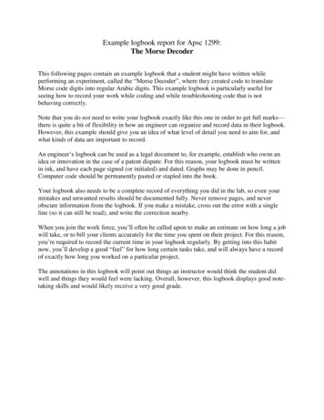
NOTE: In this paper the author is reporting values as (mean value) /- (standarddeviation ) of the data. For ME Lab I, you will usually report your values as (meanvalue) /- (maximum probable error associated with mean value).ABSTRACTThe elastic modulus, yield point, and ultimate strength of 1018 steel were determined in uniaxial tension. The"dogbone" specimen geometry was used with the region of minimum cross section having the dimensions: thickness 3.18 0.05 mm, width 6.35 0.05 mm, and gage section 38.1 0.05 mm. The elastic modulus of the specimen wasdetermined to be 196.7 GPa with a standard deviation of 2.0 GPa. The lower limit on the yield point was determined tobe 357.1 MPa with a standard deviation of 6.3 MPa. The upper limit on the yield point was determined to be385.7 MPawith a standard deviation of 6.8 MPa. The ultimate strength was determined to be 487.7 MPa with a standard deviationof 8.6 MPa.INTRODUCTIONMechanical properties are of interest to engineers utilizing materials in any application where forces are applied,dimensions are critical, or failure is undesirable. Three fundamental mechanical properties of metals are the elasticmodulus (E), the yield point ( σ y), and the ultimate strength ( σ ult). This report contains the results of an experiment todetermine the elastic modulus, yield point, and ultimate strength of 1018 steel.THEORYWhen forces are applied to materials, they deform in reaction to those forces. The magnitude of the deformationfor a constant force depends on the geometry of the materials. Likewise, the magnitude of the force required to cause agiven deformation, depends on the geometry of the material. For these reasons, engineers define stress and strain. Stress(engineering definition) is given by:σ FA(1)Defined in this manner, the stress can be thought of as a normalized force. Strain (engineering definition) is given by: li( l o )iεi (2)The strain can be thought of as a normalized deformation.While the relationship between the force and deformation depends on the geometry of the material, therelationship between the stress and strain is geometry independent. The relationship between stress and strain is given bya simplified form of Hooke's Law [1]:σ Eε(3)Since E is independent of geometry, it is often thought of as a material constant. However, E is known to depend on boththe chemistry, structure, and temperature of a material. Change in any of these characteristics must be known beforeusing a "handbook value" for the elastic modulus.Hooke's Law (Equation 3) predicts a linear relationship between the strain and the stress and describes the elasticresponse of a material. In materials where Hook's Law describes the stress-strain relationship, the elastic response is thedominant deformation mechanism. However, many materials exhibit nonlinear behavior at higher levels of stress. Thisnonlinear behavior occurs when plasticity becomes the dominant deformation mechanism. Metals are known to exhibitboth elastic and plastic response regions [2]. The transition from an elastic response to a plastic response occurs at acritical point known as the yield point ( σ y). Since a plastic response is characterized by permanent deformation(bending), the yield point is an important characteristic to know. In practice, the yield point is the stress where thestress-strain behavior transforms from a linear relationship to a non-linear relationship. The most commonly usedmethod to experimentally determine the yield point is the 0.2% offset method [3]. In this method, a line is drawn fromthe point ( σ 0, ε 0.2%) parallel to the linear region of the stress-strain graph. The slope of this line is equal to theelastic modulus. The yield point is then determined as the intersection of this line with the experimental data.In materials that exhibit a large plastic response, the deformation tends to localize. Continued deformation occursonly in this local region, and is known as necking [4]. Necking begins at a critical point known as the ultimate stress( σ ult). Since failure occurs soon after necking begins, the ultimate stress is an important characteristic to know.While many experimental tests exist to determine the mechanical properties, the simplest is the tension test. Aconvenient sample geometry for the tensile test is the "dogbone" geometry (Figure 1). In this test geometry, one end ofExample Long Reportsep01021Last Modified: 09/01/02
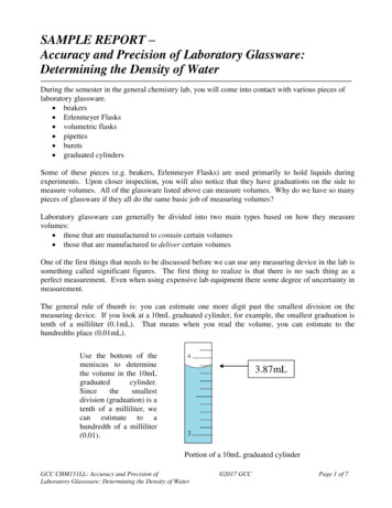
the test specimen is held fixed while the other end is pulled in uniaxial tension collinear with the long axis of the sample.The forces throughout the sample and test machine are constant, but the stress varies with cross sectional area. The stressreaches critical values first in the region of the sample of minimum cross section, and the minimum cross section is inthe sample. Therefore, the properties of the material are determined in this region.Figure 1. "Dogbone" specimen geometry used for tensile test.EXPERIMENTAL PROCEDUREA tensile test sample was machined from 1018 steel stock (106.1 mm X 19.05 mm X 3.18 mm) to the geometryshown in Figure 1. The region of minimum cross section had dimensions 6.35 mm in width, 3.18 mm in thickness, and38.1 mm in length. The error in these dimensions was 0.05 mm. This sample was clamped into an Instron UniversalTest Machine (Model 1125). The Instron test machine is a displacement controlled machine. One end of the sample washeld at a fixed position with the other end was displaced at a constant rate. A load cell (Instron model 2511-319) wasused to determine the force required to maintain a constant displacement rate. The accuracy of the load cell was 1 N.Data was collected on a strip chart (Instron model A1030) that monitored the force as a function of chart displacement.The stress in the sample at any force level can be determined from Equation 1. The calculation of strain requires theconversion of chart displacement ( δ chart) to sample displacement ( δ sample). The sample displacement can be calculatedfrom:δ sample δ chart V displacment(4)V chartThe rate of sample displacement was 1 0.01 mm/min. The rate of chart displacement was 10 0.1 mm/min. Theelastic modulus, yield point, and ultimate stress were determined from the stress-strain plot.RESULTS AND DISCUSSIONThe force-chart displacement graph for the 1018 steel examined is shown in Figure 2. The data shown in Figure 2were converted to a corresponding stress-strain graph, Figure 3. Figure 3 clearly indicates two regions of linear behaviorin the low strain region of the stress-strain graph. This behavior suggests that the sample was very compliant at lowstress levels, and very stiff at high stress levels. Unfortunately, there is no structural or chemical reason why steel shouldexhibit an increasing modulus with increasing stress. Therefore, a more probable explanation is realignment androtation of the test fixture in the low stress (low force) region. Remember, that the text fixture and the sample are underthe same applied force. Under these experimental conditions, the most compliant member will dominate the stress-strainbehavior. While the fixture appears very compliant during realignment and rotation, the fixture appears very stiff due toExample Long Reportsep01022Last Modified: 09/01/02
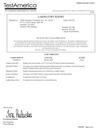
its large cross section at higher force levels. In this second region, the stress-strain behavior is dominated by the sample.Figure 2. Force as a function of chart displacement for 1018 steel tested in tension.The elastic modulus was determined from linear regression analysis of the experimental stress-strain data in thesecond linear region. This region is shown in Figure 4 along with the predicted regression line ( σ 1 [196.7 GPa] ε 2[103.2 MPa]). The elastic modulus of this steel sample was determined to be 196.7 GPa with a standard deviation of 2GPa. This estimate is consistent with a typical textbook value for modulus of plain carbon steel (205 GPa) [3].Figure 3. Stress-Strain plot for 1018 steel tested in tension.Example Long Reportsep01023Last Modified: 09/01/02
The regression line shown in Figure 4 predicts an intercept value of -103.2 MPa. This non-zero intercept suggeststhat the sample must be compressed in order to obtain zero strain. It should be noted, that this non-zero intercept resultedfrom the shift in strain values due to realignment and rotation of the fixture, and not due to permanent deformation orviolation of Hooke's Law. The region of fixture realignment and rotation creates some difficulties in determining theyield point by the 0.2% offset method. In the initial linear region, the majority of the deformation occurs in the fixtureand not in the sample. At the same time, some small amount of deformation must occur in the sample since the force inthe sample is greater than zero. The linear region used to estimate the elastic modulus of the sample, Figure 4, must beextrapolated to zero stress to determine the onset of deformation in the sample. A general regression line can bepredicted:σ Eε φ(5)The strain at zero stress ( ε σ 0 ) can be predicted from:-φEε σ 0 In the case of the relationship shown in Figure 4 (E 196.7 GPa and(6)φ 3 -103.2 MPa), the strain at zero stress wascalculated to be 5.2 x 10⁻⁴. However, si
convenient sample geometry for the tensile test is the "dogbone" geometry (Figure 1). In this test geometry, one end of σ F A (1) i i o i l (l ) ε (2) σ Eε (3) NOTE: In this paper the author is reporting values as (mean value) /- (standard deviation ) of the data. For ME Lab I,