Transcription
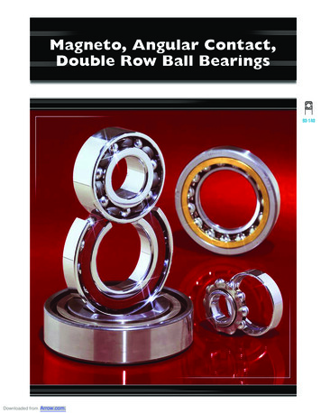
BARDENDouble Direction Angular Contact ThrustBall Bearings and Cylindrical Roller Bearings
INTRODUCTIONBORE DIAMETERS: 3mm TO 7mm Open, Shielded and Sealed Inch and Metric SeriesTABLE OF CONTENTSIntroduction .2D ouble Direction Angular Contact Thrust Ball Bearings.3Product Description and Engineering Notes .4Nomenclature.5Bearing Specification Tables.6–8Cylindrical Roller Bearings .9Product Description and Engineering Notes .10Nomenclature.11Bearing Specification Tables.12–15Barden manufactures super precision machine tool spindle bearings and instrument bearingsat plants located in Danbury, Connecticut (shown above) and the U.K.The Barden Corporation is pleased to announce theavailability of double direction angular contact thrust ballbearings and cylindrical roller bearings. These rugged,high load capacity machine tool spindle bearings arebeing manufactured by a subsidiary of our Aircraft andSuper Precision Division, in Germany.This new Barden product line complements an alreadyextensive offering of super-precision, angular contactand deep groove ball bearings. It also gives users theability to satisfy more machine tool spindle bearingrequirements from a single source.Both the double direction angular contact thrust ballbearings and cylindrical roller bearings feature a muchhigher level of rigidity for applications requiring exceptional performance under extreme loads. Special crownprofile on rollers optimizes load distribution.For application questions or ordering information,contact your Authorized Barden Distributor, or call1-800-243-1060.2
DOUBLE DIRECTIONANGULAR CONTACTTHRUST BALL BEARINGS
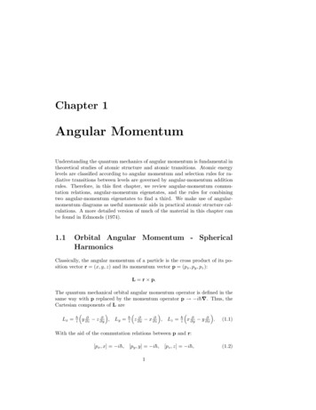
DOUBLE DIRECTION ANGULAR CONTACT THRUST BALL BEARINGSBORE DIAMETERS: 3mm TO 7mm Open, Shielded and Sealed Inch and Metric SeriesSPEEDABILITYDouble direction angular contact thrust ball bearings aredesigned for use in machine tool spindles, in combinationwith cylindrical roller bearings. They are manufacturedto precision tolerances. Double direction angular contactthrust ball bearings are designed to carry only thrustloads. They match the mounting dimensions of theN N30 Series double row cylindrical roller bearings.FAG double direction angular contact thrust ball bearingsare ideally suited for high speeds. Speed limit values forgrease and oil lubrication are given in the bearing tableson pages 6–8.LUBRICATIONFAG double direction angular contact thrust ball bearingscan be lubricated with either grease or oil. The outer ringO.D. has a lubricating groove in the center with lubricating holes. The application of the lubricant betweenthe two rows of balls allows optimal distribution oflubricant to both raceways.EXTERNAL DIMENSIONSDouble direction angular contact thrust ball bearings aredesigned to be mounted in conjunction with a doublerow radial cylindrical roller bearing. The nominal size ofthe external diameter is the same for both bearingswhich simplifies the machining of the housing bore. Theexternal diameter tolerance of the double directionangular contact thrust ball bearing is designed so that thereis clearance between the bearing O.D. and the housingbore. Use of this bearing type, in combination with adouble row cylindrical roller bearing, offers the advantageof supporting both axial and radial forces separately.RIGIDITYFor optimum performance, machine tool spindle bearingsmust exhibit high rigidity as well as high precision. Thismeans that they must run precisely and must allow onlyslight deflection under load. The double direction angularcontact thrust ball bearings achieve high rigiditythrough their internal design with steep contact angleand internal defined preload (see table 1).BEARING DESIGNDouble direction angular contact thrust ball bearingshave a contact angle of 60 and are axially preloaded.They are particularly well suited for running at highspeeds. The contact angle and the axial preload ensuresgood ball control, especially under the centrifugal forceswith fast rotating spindles. These bearings are designedto accommodate high thrust loads. They have solid onepiece machined brass cages which are ball guided.WorkheadDri ve EndFig. 1. This illustration of a milling spindle shows typical placement of a double directionangular contact thrust ball bearing used in combination with a double row cylindrical rollerbearing in the workhead. The drive end of the spindle features one double row cylindricalbearing. This combination allows the spindle to operate at high speeds at high rigidity, whileaccommodating both axial and radial loads.4
BEARING NOMENCLATURE Open, Shielded and Sealed Inch and Metric SeriesExample: 234410M.SPSERIES TYPE2344 – For assembly on the smallerside of the NN30 taper.2347 – For assembly on the largerside of the NN30 taper.2344PRECISIONSP – Super precision.10MBORE SIZE CODESPCAGE10 – 10 5 50 mm.M – Brass cage.Table 1. Axial rigidity of double direction angular contact thrust ball bearings.Bore Reference ./µin.Bore Reference 12.112.612.913.814.3F a axial load [lb.]S a rigidity [lb./µin.]a F ax/S ar axial deflection [µin.]These values apply up to an axial load equivalent to 2.2% of the dynamic capacity C.5
DOUBLE DIRECTION ANGULAR CONTACT THRUST BALL BEARINGS2344, 2347 Contact angle 60 BEARINGNUMBERLOADRATINGBEARING DIMENSIONS (in 0GreaseOilWeight 9.520,92554,0003,2004,30012.36
BEARINGNUMBERLOADRATINGBEARING DIMENSIONS (in t.C0GreaseOilWeight 60M.SP3004604061909547.541.5101,250 47.541.517.7101,250 41.517.7102,375 41.517.7102,375 1.517.7121,500 1.517.7121,500 1.517.7121,500 1.517.7121,500 1.517.7126,000 1.517.7126,000 495,0001,0001,500317.57
BEARINGNUMBERLOADRATINGBEARING DIMENSIONS (in PEEDWEIGHTdyn.Cstat.C0GreaseOilWeight 3417.7285,7501,3001,800140.7101,250 344,2501,2001,700216.917.7101,250 344,2501,2001,700201.11.517.7102,375 366,7501,2001,700224.91.517.7102,375 366,7501,2001,700209.21.517.7121,500 65341.517.7121,500 1.517.7121,500 1.517.7121,500 1.517.7126,000 1.517.7126,000 495,0001,0001,500317.57
CYLINDRICALROLLER BEARINGS
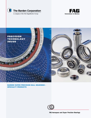
CYLINDRICAL ROLLER BEARINGSN10 Open, Shielded and Sealed Inch and Metric SeriesBEARING DESIGNSuper precision cylindrical roller bearings are designatedas Series N10 and NN30.These double row bearings are typically used in combination with double direction angular contact thrustbearings in applications where radial stiffness, high radialcapacity and high precision support is required. Theyrepresent the ideal solution for a floating bearing location,since they are internally adjusting (floating).For axial loads, double direction angular contactthrust bearings, Series 2344 are used in combinationwith Series NN30 bearings.A single row bearing would be most commonly usedas the “floating” bearing in combination with a set ofpreloaded angular contact spindle bearings.Dri ve EndDouble row cylindrical roller bearings have a high loadcarrying capacity because of the high number of cylindrical rollers in each row, and the exclusive optimized rollercrown profile which results in the best load distribution.The cage is of solid machined brass construction,making this bearing suitable for rugged applications.Single row cylindrical roller bearings also have a solidbrass cage and are specially designed for the demands ofhigh speed spindles. These also feature rollers with anexclusive, optimized roller crown design.The bearing bore is tapered (taper 1: 12). Thedesired radial preload or radial clearance can be set byan axial adjustment on the conical shaft. Generally, thebearings should be mounted with zero clearance to avery slight preload.WorkheadSPEEDABILITYCylindricals generally have lower limiting speed thanball bearings. They are the limiting factor when usedin conjunction with spindle bearings on the work end ofa spindle.LUBRICATIONFAG cylindrical roller bearings can be lubricated withFig. 2. Illustration shows a CNC lathe spindle with a single row cylindrical roller bearing either grease or oil.used in the drive end. One single and one pair of angular contact balls bearings is used in the Double row bearings feature a lubricating groove andworkhead end of the spindle. The combination provides high speed and precision machininglubricating hole in the middle of the outer ring.capabilities with high radial load carrying capacity.RIGIDITYCylindrical roller bearings have a higher rigidity thancomparable size angular contact ball bearings (see table 3).Table 2. Radial play of FAG Cylindrical Roller Bearings with tapered bore.Dimensions in mmNominalbearing boreOverto 0Radial play in µmBearing 20135150170190The standard radial clearance of Precision SP is C1NA.10
BEARING NOMENCLATURE Open, Shielded and Sealed Inch and Metric SeriesEXAMPLE: NN3008ASK.M.SPTYPEN – Single row, shoulderson the inner ring.NN – Double row, shoulderson the inner ring.BORESIZE CODE08 – 8 5 40 mm.30NNCAGEM1 – Brass cage single row.M – Brass cage double row.08DIMENSIONALSERIES10 – Single row bearings.30 – Double row bearings.ASKMSPTAPERED BOREPRECISIONK – Tapered bore, single rowbearing.ASK – Tapered bore, lubrication holes in OR double rowbearing.SP – Super precision.Table 3. Radial rigidity of cylindrical roller bearings.Bore .15.35.86.06.26.57.07.58.0r F r/C sCsNN30lb./µin.Bore .633.133.336.240.341.743.248.7r radial deflection [µin.]F r radial load [lb.]11C s rigidity [lb./µin.]
CYLINDRICAL ROLLER BEARINGSN10BEARINGNUMBERLOADRATINGBEARING DIMENSIONS (in 0Greaselbs.lbs.rpmOilminimalWEIGHTWeight 380560825515265,500450,0001,3001,500146.812
BEARINGNUMBERLOADRATINGBEARING DIMENSIONS (in 22,0001,200Oilminimal1,400WEIGHTWeight 6,000720,0009501,100286.613
CYLINDRICAL ROLLER BEARINGSNN30 Open, Shielded and Sealed Inch and Metric SeriesBEARINGNUMBERLOADRATINGBEARING DIMENSIONS (in n.Cstat.C0GreaseOilWeight 60135551317.79382,500776,2501,3001,600251.314
BEARINGNUMBERLOADRATINGBEARING DIMENSIONS (in OilWeight 2501,316,2501,0001,300491.615
The Barden CorporationA Member of the Schaeffler Group.Insist on Precision200 Park AvenueP.O. Box 2449Danbury, CT 06813-2449www.bardenbearings.com
contact your Authorized Barden Distributor, or call 1-800-243-1060. Barden manufactures super precisionmachine tool spindle bearings and instrumentbearings at plants l