Transcription
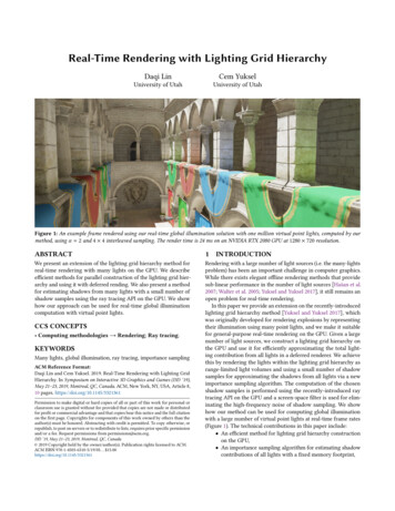
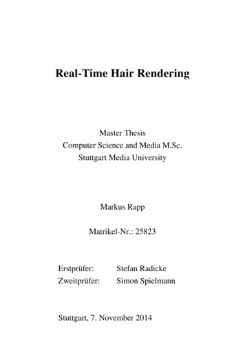
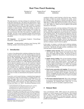
Appears in Game Developers Conference 2002 ProceedingsReal-Time Cloud Rendering for GamesMark J. HarrisDepartment of Computer Science, University of North Carolina at Chapel Hillharrism@cs.unc.edu, http://www.cs.unc.edu/ harrism/cloudsAbstractThis paper presents a method for realistic real-time rendering of clouds for flight simulators andgames. It describes a cloud illumination algorithm that approximates multiple forwardscattering in a preprocess, and first order anisotropic scattering at runtime. Impostors areused to accelerate cloud rendering by exploiting frame-to-frame coherence in an interactiveflight simulation. Impostors are particularly well suited to clouds, even in circumstances underwhich they cannot be applied to the rendering of polygonal geometry. The method allowshundreds of clouds with hundreds of thousands of particles to be rendered at high frame rates,and improves interaction with clouds by reducing artifacts introduced by direct particlerendering.1 IntroductionClouds are an integral feature of the sky;without them synthetic outdoor scenesseem unrealistic. Game developers knowthis; outdoor games nearly always haveclouds present. If the player’s viewpointstays near the ground, then the game canrely on techniques similar to those used byrenaissance painters in ceiling frescos:distant and high-flying clouds arerepresented by paintings on an alwaysdistant sky dome. Flight simulators andother flying games don’t have it so easy –their players’ viewpoints are free to roamthe sky.Many techniques have been used forFigure 1: Realistic clouds in the game “Savage Skies”.clouds in games and flight simulators. Theyhave been hinted at with planar textures –both static and animated – or with semi-transparent textured objects and fogging effects.These techniques leave a lot of effects to be desired. In a flying game, we would like to fly inand around realistic, volumetric clouds, and to see other flying objects pass within and behindthem. This paper describes a system for real-time volumetric cloud shading and rendering thatis appropriate for games and flight simulators.This paper focuses on high-speed, high-quality rendering of constant-shape clouds for games.Games are complex systems that are very computationally and graphically loaded, so cloudrendering must be very fast. For this reason, we render realistically shaded static clouds, and1
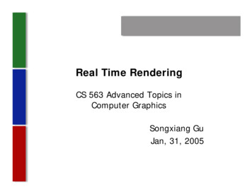
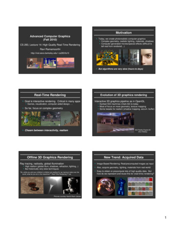
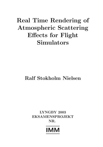
Appears in Game Developers Conference 2002 Proceedingsdo not address issues of dynamic cloudsimulation. This choice enables us togenerate clouds ahead of time, and toassume that cloud particles are static relativeto each other. This assumption speeds cloudrendering because we need only shade themonce per scene in a preprocess.The rest of this section presents previouswork. Section 2 gives a derivation anddescription of our shading algorithm. Section3 discusses dynamically generated impostorsand shows how we use them to accelerateFigure 2: A view from an interactive flight throughcloud rendering. We also discuss how weclouds.have dealt with issues in interacting withclouds. Section 4 discusses our results and presents performance measurements. Weconclude and discuss ideas for future research in section 5.This paper is based on [Harris 2001]. More information, images, lecture notes, and tutorialmaterial can be found at http://www.cs.unc.edu/ harrism/clouds.1.1 Previous WorkTwo areas of previous work are important to this paper: cloud modeling and cloud rendering.Cloud modeling deals with the data used to represent clouds in the computer, and how thedata are generated and organized. We build our clouds with particle systems. Reevesintroduced particle systems as an approach to modeling clouds and other such “fuzzy”phenomena in [Reeves1983]. Voxels are another common representation for clouds. Voxelmodels provide a uniform sampling of the volume, and can be rendered with both forward andbackward methods. Procedural solid noise techniques are also important to cloud modeling asa way to generate random but continuous density data to fill cloud volumes [Lewis1989,Perlin1985, Ebert1998].Rendering clouds is difficult because realistic shading requires the integration of the effects ofoptical properties along paths through the cloud volume, while incorporating the complex lightscattering within the medium. Previous work has attempted to approximate the physicalcharacteristics of clouds at various levels of accuracy and complexity, and then to use theseapproximate models to render images of clouds. Blinn introduced the use of density modelsfor image synthesis in [Blinn1982], where he presented a low albedo, single scatteringapproximation for illumination in a uniform medium. Kajiya and Von Herzen extended thiswork with methods to ray trace volume data exhibiting both single and multiple scattering[Kajiya1984]. Max provided an excellent survey in which he summarized the spectrum ofoptical models used in volume rendering and derived their integral equations from physicalmodels [Max1995]. David Ebert has done much work in modeling “solid spaces”, includingoffline computation of realistic images of smoke, steam, and clouds [Ebert1990, Ebert1997].Nishita et al. introduced approximations and rendering techniques for global illumination ofclouds accounting for multiple anisotropic scattering and skylight [Nishita1996].2
Appears in Game Developers Conference 2002 ProceedingsOur rendering approach draws most directly from the rendering technique presented byDobashi et al [Dobashi2000]. The shading method presented by Dobashi et al. implements anisotropic single scattering approximation. We extend this method with an approximation tomultiple forward scattering and anisotropic first order scattering. The animated cloud scenesof Dobashi et al. required 20-30 seconds rendering time per frame. Our system renders staticcloudy scenes at tens to hundreds of frames per second, depending on scene complexity.2 Shading and RenderingParticle systems are a simple and efficient method for representing and rendering clouds. Ourcloud model assumes that a particle represents a roughly spherical volume in which aGaussian distribution governs the density falloff from the center of the particle. Each particle ismade up of a center, radius, density, and color. We get good approximations of real clouds byfilling space with particles of varying size and density. Clouds in our system can be built byfilling a volume with particles, or by using an editing application that allows a user to placeparticles and build clouds interactively. The randomized method is a good way to get a quickfield of clouds, but games have levels designed and built by artists who require fine controlover all details of the scene. Providing an artist with an editor allows the artist to producebeautiful clouds tailored to the needs of the game.We render particles using splatting [Westover1991], by drawing screen-oriented polygonstexture-mapped with a Gaussian density function. Although we choose a particle systemrepresentation for our clouds, it is important to note that both our shading algorithm and ourfast rendering system are independent of the cloud representation, and can be used with anymodel composed of discrete density samples in space.2.1 Essential DefinitionsTo improve clarity in the next few sections, we will define some terms.Absorption is the phenomenon by which light energy is converted into another form uponinteracting with particles in a medium. For example, your skin grows warm in sunlight becausesome of the light is absorbed and transformed into heat energy.Scattering is the phenomenon of absorption and reradiation of light by a medium.Extinction describes the attenuation of light energy by absorption and scattering:Extinction Scattering Absorption.Any light that interacts with a medium undergoes either scattering or absorption. If it does notinteract, then it is transmitted. Extinction (and therefore scattering and absorption) isproportional to density.Single Scattering is scattering of light by a single particle:In optically thin media (media that are either physically very thin, or very transparent),scattering of light can be approximated using single scattering models. Clear air can usuallybe approximated this way, but clouds cannot.3
Appears in Game Developers Conference 2002 ProceedingsMultiple Scattering is scattering of light from multiple particles in succession:Models that account for only single scattering cannot accurately represent optically thick mediasuch as clouds. Multiple scattering is the reason that clouds appear much brighter (and whiter)than the sky. Most of the light that emerges from a cloud has been scattered many times.Optical Depth: a measure of how opaque a medium is to light passing through it. It has unitsof one over length (such as cm-1), and can be thought of as one over the distance light musttravel into a medium before all of its intensity has been either absorbed or scattered.Albedo: (may also be called scattering coefficient) the percentage of attenuation by extinctionthat is due to scattering by a medium rather than absorption.Albedo Scattered Power / Incident Power Scattering / Extinction.Phase Function: a function that determines, for any angle between incident and outgoingdirections, how much of the incident light intensity will be scattered in the outgoing direction.For example, scattering by very small particles such as those found in clear air, can beapproximated using Rayleigh scattering. The phase function for Rayleigh scattering isp(θ) 3/4(1 cos2θ),where θ is the angle between incident and scattered directions. Scattering by larger particlesis more complicated. It is described by Mie scattering theory, which is outside the scope of thispaper. Cloud particles are more in the regime of Mie scattering than Rayleigh scattering.However, we obtain good visual results by using the simpler Rayleigh scattering phasefunction as an approximation.2.2 Light Scattering IlluminationScattering illumination models simulate the emission and absorption of light by a medium aswell as scattering through the medium. Single scattering models simulate scattering throughthe medium in a single direction. This direction is usually the direction leading to the point ofview. Multiple scattering models are more physically accurate, but must account for scatteringin all directions (or a sampling of all directions), and therefore are much more complicated andexpensive to evaluate. The rendering algorithm presented by Dobashi et al. computes anapproximation of illumination of clouds with single scattering. This approximation has beenused previously to render clouds and other participating media [Blinn1982, Kajiya1984].In a multiple scattering simulation that samples N directions on the sphere, each additionalorder of scattering that is simulated multiplies the number of simulated paths by N.Fortunately, as demonstrated by [Nishita1996], the contribution of most of these paths isinsignificant to cloud rendering. Nishita et al. found that scattering illumination is dominated bythe first and second orders, and therefore they only simulated up to the 4th order. They reducethe directions sampled in their evaluation of scattering to sub-spaces of high contribution,which are composed mostly of directions near the direction of forward scattering and thosedirected at the viewer. We simplify further, and approximate multiple scattering only in the light4
Appears in Game Developers Conference 2002 Proceedingsdirection – or multiple forward scattering – and anisotropic single scattering in the eyedirection.Our cloud rendering method is a two-pass algorithm similar to the one presented in[Dobashi2000]: we precompute cloud shading in the first pass, and use this shading to renderthe clouds in the second pass. The algorithm of Dobashi et al., however, uses only anisotropic first order scattering approximation. If realistic values are used for the optical depthand albedo of clouds shaded with only a first order scattering approximation, the clouds appearvery dark [Max1995]. This is because much of the illumination in a cloud is a result of lightscattered forward along the light direction. Figures 9 and 10 show the difference inappearance between clouds shaded with and without our multiple forward scatteringapproximation.2.2.1. Multiple Forward ScatteringThe first pass of our shading algorithm computes the amount of light incident on each particleP in the light direction, l. This light, I(P, l), is composed of all direct light from direction l that isnot absorbed by intervening particles, plus light scattered to P from other particles. Themultiple scattering model is writtenDPI (P, ω) I 0 e τ (t ) dt0DPDP g(s, ω)e τ (t ) dtsds, (1)0where DP is the depth of particle P in the cloud along the light direction, andg ( x,ω ) r ( x,ω ,ω ' ) I ( x,ω ')dω '(2)4πrepresents the light from all directions ω ′ scattered into direction ω at the point x. Herer(x,ω,ω’) is the bi-directional scattering distribution function (BSDF). It determines thepercentage of light incident on x from direction ω ′ that is scattered in direction ω. It expands tor(x,ω,ω ′) a(x) τ(x) p(ω,ω ′), where τ(x) is the optical depth, a(x) is the albedo, and p(ω,ω ′) is thephase function.A full multiple scattering algorithm must compute this quantity for a sampling of all light flowdirections. We simplify our approximation to compute only multiple forward scattering in thelight direction, so ω l, and ω ′ -l. Thus, (2) reduces to g(x,l) r(x,l,-l) I(x,-l) / 4π.We split the light path from 0 to DP into discrete segments sj, for j from 1 to N, where N is thenumber of cloud particles along the light direction from 0 to DP. By approximating the integralswith Riemann Sums, we haveNIP I0 ej 1 τj NN j 1gj e τ k .(3)k j 1I0 is the intensity of light incident on the edge of the cloud. In discrete form g(x,l) becomes gk ak τk p(l,-l) Ik / 4π. We assume that albedo and optical depth are represented at discretesamples (particles) along the path of light. In order to easily transform (3) into an algorithmthat can be implemented in graphics hardware, we rewrite it as an equivalent recurrencerelation:5
Appears in Game Developers Conference 2002 Proceedings g Tk 1 I k 1 , 2 k N.I k k 1I0 ,k 1 (4)If we let Tk e τ be the transparency of particle pk, then (4) expands to (3). This representationcan be more intuitively understood. It simply says that starting outside the cloud, as we tracealong the light direction the light incident on any particle pk is equal to the intensity of lightscattered to pk from pk-1 plus the intensity transmitted through pk-1 (as determined by itstransparency, Tk-1). Notice that if gk is expanded in (4) then Ik-1 is a factor in both terms.Section 2.3 explains how we combine frame buffer read back with hardware blending toefficiently evaluate this recurrence.k2.2.2. Eye ScatteringIn addition to our multiple forward scattering approximation, which we precompute, we alsoimplement single scattering toward the viewer as in [Dobashi2000]. The recurrence for this issubtly different:E k S k T k E k 1 ,1 k N.(5)This says that the light, Ek, exiting any particle pk is equal to the light incident on it that it doesnot absorb, Tk · Ek-1, plus the light that it scatters, Sk. In the first pass described in Section 2.2.1,we computed the light Ik incident on each particle from the light source. In the second pass weare interested in the portion of this light that is scattered toward the viewer. When Sk isreplaced by ak τk p(ω, -l) Ik / 4π, where ω is the view direction and Tk is as above, this recurrenceapproximates single scattering toward the viewer. It is important to mention that (5) computeslight emitted from particles using results (Ik) computed in (4). Since illumination is multiplied bythe phase function in both recurrences, one might think that the phase function is multipliedtwice for the same light. This is not the case, since in (4), Ik-1 is multiplied by the phasefunction to determine the amount of light Pk-1 scatters to Pk in the light direction, and in (5) Ik ismultiplied by the phase function to determine the amount of light that Pk scatters in the viewdirection. Even if the viewpoint is directly opposite the light source, since the light incident onPk is stored and used in the scattering computation, the phase function is never taken intoaccount twice at the same particle.2.2.3. Phase FunctionThe phase function, p(ω,ω’) mentioned above is very important to cloud shading. Cloudsexhibit anisotropic scattering of light (including the strong forward scattering that we assume inour multiple forward scattering approximation). The phase function determines the distributionof scattering for a given incident light direction. Phase functions are discussed in detail in[Nishita1996], [Max1995], and [Blinn1982], among others. The images shown in this paperwere generated using a simple Rayleigh scattering phase function given in section 2.1.Rayleigh scattering favors scattering in the forward and backward directions. Figures 11 and12 demonstrate the differences between clouds shaded with and without anisotropicscattering. Anisotropic scattering gives the clouds their characteristic “silver lining” whenviewed looking into the sun.6
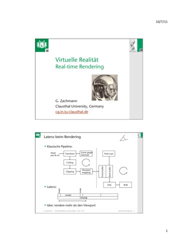
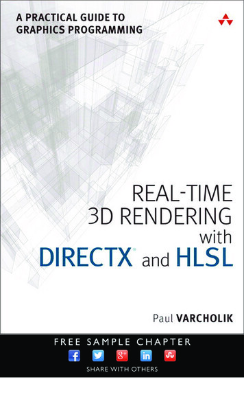
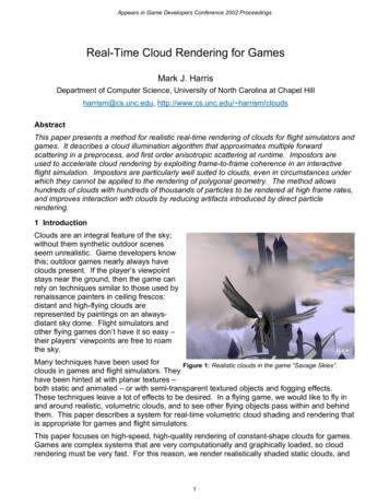
Appears in Game Developers Conference 2002 Proceedings2.3 Rendering AlgorithmArmed with recurrences (4) and (5) and astandard graphics API such as OpenGL orDirect3D, computation of cloud illuminationis straightforward. Our algorithm is similarto the one presented by [Dobashi2000]and has two phases: a shading phase thatruns once per scene and a renderingphase that runs in real time. The key tothe implementation is the use of hardwareblending and pixel read back.Blending operates by computing aweighted average of the frame bufferFigure 3: Clouds hang low over a valley.contents (the destination) and an incomingfragment (the source), and storing the result back in the frame buffer. This weighted averagecan be writtenc result f src c src f dest c dest(6)If we let cresult Ik, fsrc 1, csrc gk-1, fdest Tk-1, and cdest Ik–1, then we see that (4) and (6) areequivalent if the contents of the frame buffer before blending represent I0. This is not quiteenough, though, since as we saw before, Ik-1 is a factor of both terms in (4). To solve therecurrence for a particle pk, we must know how much light is incident on particle pk-1beforehand. To do this, we employ pixel read back.To compute (4) and (5), we use the procedure described by the pseudocode in figure 4. Thepseudocode shows that we use a nearly identical algorithm for preprocess and runtime. Thedifferences are as follows. In the illumination pass, the frame buffer is cleared to white andparticles are sorted with respect to the light. As a particle is blended into the frame buffer,blending attenuates the intensity of each fragment by the opacity of the particle, and increasesthe intensity by the amount the particle scatters in the forward direction. The percentage oflight that reaches pk, is found by reading back the color of the pixel in the frame buffer to whichthe center of the particle projects immediately before rendering pk. Ik is computed bymultiplying this percentage by the light intensity. Ik is used to compute multiple forwardscattering in (4) and eye scattering in (5).The runtime phase uses the same algorithm, with particles sorted with respect to theviewpoint, and without reading pixels. The precomputed illumination of each particle Ik is usedin this phase to compute scattering toward the eye.In both passes, we render particles in sorted order as polygons textured with a Gaussian“splat” texture. The polygon color is set to the scattering factor ak τk p(ω,l) Ik / 4π and the textureis modulated by this color. In the first pass, ω is the light direction, and in the second pass it isthe direction of the viewer. The source and destination blending factors are set to one and oneminus source alpha, respectively. All cloud images in this paper were computed with aconstant τ of 8.0, and an albedo of 0.9.7
Appears in Game Developers Conference 2002 ProceedingsSource blend factor 1;destination blend factor 1 – source alpha;texture mode modulate;l direction from light;if (preprocess) thenω -l;view cloud from light source;clear frame buffer to white;particles.Sort( , distance to light);elseview cloud from eye position;particles.Sort( ,distance from eye);endif[Sort( , dist. from x) sort in ascending order by dist. from x, descending ]foreach particle pk [pk has extinction τk, albedo ak, radius rk, color, and alpha]if (preprocess) thenx pixel at projected center of pk;ik color(x) * light color;pk.color ak * τk * ik / 4π;pk.alpha 1 - exp(-τk);elseω pk.position – view position;endifc pk.color * phase(ω, l);render pk with color c, side 2*rk;end2.3.1. SkylightThe most awe-inspiring images of clouds are created by the multi-colored spectacle of abeautiful sunrise or sunset. These clouds are often not illuminated directly by the sun at all,but by skylight – sunlight that is scattered by the atmosphere. The fact that light accumulatesin an additive manner provides us with a simple extension to our shading method that allowsthe creation of such beautiful clouds. We simply shade clouds from multiple light sources andstore the resulting particle colors (ik in the algorithm above) from all shading iterations. AtFigure 4: Pseudocode for cloud shading and rendering.render time, we evaluate the phase function at each particle once per light. By doing so, wecan approximate global illumination of the clouds.While this technique is not completely physically-based, it is better than an ambient lightapproximation, since it is directional and results in shadowing in the clouds as well asanisotropic scattering from multiple light directions and intensities. We obtained best results byusing the images that make up the sky dome we place in the distance over our environmentsto guide the placement and color of lights. Figure 13 shows a scene at sunset in which we usetwo light sources, one orange and one pink, to create sunset lighting. In addition to8
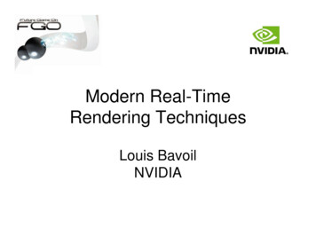
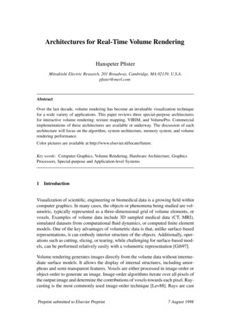
Appears in Game Developers Conference 2002 Proceedingsillumination from multiple light sources, we provide an ambient term to provide somecompensation for scattered light lost due to our scattering approximation.3 Dynamically Generated ImpostorsWhile the cloud rendering methoddescribed above provides beautifulresults and is fast for relatively simplescenes, it suffers under the weight ofmany complex clouds. The games forwhich we developed this system dictatethat we must render complicated cloudscenes at fast interactive rates. Cloudsare only one component of a complexgame environment, and therefore canonly use a small percentage of a frametime. With direct particle rendering, evena scene with ten or twenty thousandparticles is prohibitively slow on currenthardware.Figure 5: Impostors, outlined in this image, are texturedpolygons oriented toward the viewer.The integration (section 2.2) required toaccurately render volumetric media results in high rates of pixel overdraw. Clouds haveinherently high depth complexity, and require blending, making rendering them a difficult jobeven for current hardware with the highest fill rates. In addition, as the viewpoint approaches acloud, the projected area of that cloud’s particles increases, becoming greatest when theviewpoint is within the cloud. Thus, pixel overdraw is increased and rendering slows as theviewpoint nears and enters clouds.In order to render many clouds made up of many particles at high frame rates, we need a wayto bypass fill rate limitations, either by reducing the amount of pixel overdraw performed, or byamortizing the rendering of cloud particles over multiple frames. Dynamically generatedimpostors allow us to do both.[Maciel1995], [Schaufler1995], and [Shade1996] all discuss impostors. An impostor replacesan object in the scene with a semi-transparent polygon texture-mapped with an image of theobject it replaces (figure 5). The image is a rendering of the object from a viewpoint V that isvalid (within some error tolerance) for viewpoints near V. Impostors used for appropriatepoints of view give a very close approximation to rendering the object itself. An impostor isvalid (with no error) for the viewpoint from which its image was generated, regardless ofchanges in the viewing direction. Impostors may be precomputed for an object from multipleviewpoints, requiring much storage, or they may be generated only when needed. We choosethe latter technique, called dynamically generated impostors by [Schaufler1995].We generate impostors using the following procedure. A view frustum is positioned so that itsviewpoint is at the position from which the impostor will be viewed, and it is tightly fit to thebounding volume of the object (figure 6). We then render the object into an image used totexture the impostor polygon.9
Appears in Game Developers Conference 2002 ProceedingsAs mentioned above, we can use impostors toamortize the cost of rendering clouds overmultiple frames. We do this by exploiting theframe-to-frame coherence inherent in threedimensional scenes: the relative motion ofobjects in a scene decreases with distance fromthe viewpoint, and objects close to the viewpointpresent a similar image for some time. This lackof sudden changes in the image of an objectallows us to re-use impostor images overmultiple frames. We can compute an estimateof the error in an impostor representation thatwe use to determine when the impostor needsFigure 6: Impostor generation and translation errormetric.to be updated. Certain types of motionintroduce error in impostors more quickly thanothers. [Schaufler1995] presents two worst-case error metrics for this purpose. The first,which we will call the translation error, computes error caused by translation away from theviewpoint at which the current impostor was generated. The second computes errorintroduced by moving straight toward the object, which we call the zoom error.We use the same translation error metric, and replace zoom error by a texture resolution errormetric. For the translation error metric, we simply compute the angle αtrans, shown in figure 6,and compare it to a specified tolerance. The zoom error metric compares the current impostortexture resolution to the required resolution for the texture, computed using the followingequation [Schaufler1995]resolution texture resolution screen object size.object distIf either the translation error is greater than an error tolerance angle or the current resolution ofthe impostor is less than the required resolution, we regenerate the impostor from the currentviewpoint. We find that a tolerance of about 0.15 degree reduces impostor “popping” to animperceptible level while maintaining good performance. For added performance, tolerancesup to one degree can be used with more noticeable (but not excessive) popping.In the past, impostors were used mostly to replace geometric models. Since these modelshave high frequencies in the form of sharp edges, impostors have usually been used only fordistant objects. Nearby objects must have impostor textures of a resolution at or near that ofthe screen, and their impostors require frequent updates. We use impostors for clouds nomatter where they are in relation to the viewer. Clouds do not have high frequency edges likethose of geometric models, so artifacts caused by low texture resolution are less noticeable.Clouds have very high fill rate requirements, so cloud impostors are beneficial even when theymust be updated every few frames.3.1 Head in the CloudsImpostors can provide a large reduction in overdraw even for viewpoints inside the cloud,where the impostor must be updated every frame. The “foggy” nature of clouds makes itdifficult for the viewer to discern detail when inside them. In addition, in games and flight10
Appears in Game Developers Conference 2002 Proceedingssimulators, the viewpoint is often moving. These factors allow us to reduce the resolution atwhich we render impostor textures for clouds containing the viewpoint by about a factor of 4 ineach dimension.However, impostors cannot be generated in the same manner for these clouds as for distantclouds, since the view frustum cannot be tightly fit to the bounding volume as described above.Instead, we use the same frustum used to display the whole scene to generate the texture forthe impostor, but create the texture at a lower resolution, as described above. We displaythese impostors as screen-space rectangles sized to fill the screen.3.1.1. Objects in the CloudsIn order to create effective interactive cloudyscenes, we must allow objects to pass in andthrough the clouds, and we must render thisrealistically. Impostors pose a problem becausethey are two-dimensional. Objects that passthrough impostors appear as if they are passingthrough images floating in space, rather thanthrough fluffy, volume-filling clouds.Figure 7: An airplane in the clouds. On the left,One way to solve this problem would be to detect particles are directly rendered into the scene.clouds that contain objects and render theirArtifacts of their intersection with the plane areparticles directly to the frame buffer. By doing so, visible. On the right, the airplane is renderedbetween impostor layers, and no artifacts arehowever, we lose the benefits that impostorsprovide us. Instead, we detect when objects pass visible.within the bounding volume of a cloud, and split the impostor representing that cloud intomultiple layers. If only one object resides in a certain cloud, then that cloud is rendered as twolayers: one for the portion of cloud particles that lies approximately behind the object withrespect to the viewpoint, and o
them. This paper describes a system for real-time volumetric cloud shading and rendering that is appropriate for games and flight simulators. This paper focuses on high-speed, high-quality rendering of constant-shape clouds for games. Games are complex systems that are very computationally an