Transcription
BRIDGE ENGINEERINGJUNE 2008
NOTE: JULY 2018The Timber Bridge Manual is a reference documentonly. Some of the contents are out-of-date.It is recommended to seek advice from RMS Bridgeand Structural Engineering (Rehabilitation Design) priorto use.TIMBER BRIDGE MANUALEDITION 1 REVISION 0 - JUNE 2008This manual is provided for the guidance of designers and fieldstaff.Users are advised that in the event of any inconsistencybetween this manual and other RTA specifications, the lattershall take precedence.If users are in doubt about any issue, please contactRehabilitation Design Section of Bridge Engineering Branch forclarification.
Prepared by Bridge EngineeringEngineering Technology BranchRoads and Traffic Authority of NSW Copyright – Roads and Traffic Authority of NSW, 2008Printed June 2008APPROVEDWije AriyaratnePRINCIPAL BRIDGE ENGINEERDATE30/06/2008
INTRODUCTION TO TIMBER BRIDGE MANUALThis manual is intended to replace all existing RTA/DMR publicationsconcerning timber bridge maintenance, including ‘Manual No. 6 - BridgeMaintenance’ (DMR, 1962 and re-issued 1983) and to complement the ‘TimberTruss Bridge Maintenance Handbook’ (DMR, 1987). It is intended for use byboth designers and field personnel. This introduction outlines the basic scopeand objectives of the manual.ScopeThis manual comprises eight sections and encompasses the maintenance andrehabilitation of all timber bridge types including trusses, beam/girder spans,stress laminated bridges, concrete overlays, timber-concrete composites aswell as timber substructures.Issues covered include the following: structure typesinspectionpreventative and routine maintenancerehabilitation and repairsguidance for engineering designdetailing and durabilityspecificationsmaterial supplyObjectivesThe primary objective of this manual is to capture the RTA’s corporateknowledge of best practice in timber bridge maintenance.While the manual incorporates, where applicable, all existing documentationand policy, its main purpose has been to document current field practices. TheRTA’s bridge maintenance personnel have successfully maintained timberbridges using methods and practices derived from long term experience.Success has depended on this body of knowledge being verbally passed downfrom the dwindling pool of field “experts” to their successors. This knowledgehas now been fully documented in this manual.Another objective of the manual is to produce a document which will standalone, requiring a minimum of reference to other information. It is intended foruse at both the design and field construction level in such a way that theconsiderations of both levels are properly integrated. This is important becausethe design/detailing of timber elements plays a major role in the quality anddurability of timber bridges.(i)
CONTENTSSECTION ONETIMBER BRIDGES – GENERALSECTION TWOTIMBER SUBSTRUCTURESSECTION THREETIMBER TRUSS BRIDGESSECTION FOURTIMBER GIRDERS, DECKING AND SHEETINGSECTION FIVESTRESS LAMINATED TIMBER SYSTEMSSECTION SIXTIMBER CONCRETE OVERLAY BRIDGESSECTION SEVENTIMBER CONCRETE COMPOSITE BRIDGESSECTION EIGHTPRESERVATIVE AND PROTECTIVE TREATMENTS(ii)
TIMBER BRIDGE MANUALEdition 1 Revision 0 – June 2008SECTION ONETIMBER BRIDGES – GENERAL
TIMBER BRIDGE MANUALEDITION 1 R 0TABLE OF CONTENTSSECTION ONE1.1TIMBER BRIDGES1. 1GENERAL1. 1.1Scope1. 1.2Objectives1. 1.3Features1. 1.4Limits of Application of the Manual1. 1.5Definitions1111121. 2STRUCTURE TYPES AND COMPONENTS1. 2.1Wood as an Engineering Material1. 2.2Timber Bridge (Types) Systems1. 2.2.1 Timber Substructures1. 2.2.2 Timber Sheeting1. 2.2.3 Timber Decking1. 2.2.4 Timber Girders1. 2.2.5 Timber Trusses (and Cross Girders)1. 2.2.6 Stress Laminated Timber Systems1. 2.2.7 Concrete Overlays1. 2.2.8 Timber Concrete Composite Systems1. 2.3Traffic Barriers1. 2.4Wearing Surfaces4567789910111112131. 3INSPECTION PROCEDURES1. 3.1Objectives1. 3.2General Requirements1. 3.3Inspection Records1. 3.4Types and Frequency of Inspections1. 3.5Visual Inspection1. 3.5.1 Inspection Under Transient Loading1. 3.5.2 Structural Damage and Defects1. 3.5.3 Timber Deterioration1. 3.5.4 Summary of Visual Inspection1. 3.6Detailed Inspection1. 3.7Boring of Timber Components1. 3.7.1 General Requirements for Timber Boring1. 3.7.2 Boring Records1. 3.7.3 Boring Terminologies1. 3.7.4 Example Boring Records141415151515161616171718181819191. 4MAINTENANCE1. 4.1Objectives1. 4.2General Requirements1. 4.3Preventative Maintenance20202021(i)
1. 4.41. 4.51. 4.61. 4.7Types and Frequency of MaintenanceAnnual MaintenanceThree Year MaintenanceTreatment of Fungal and Insect Attack212122221. 5REHABILITATION AND REPAIRS1. 5.1Remedial and Temporary Repairs1. 5.2Assessment of Remedial and Temporary Repairs1. 5.3Assessment of Repairs to Primary Structural Components1. 5.4Rehabilitation and Component Replacement22232324241. 6ENGINEERING EVALUATION1. 6.1Design Specifications1. 6.2Timber Grade for Strength Assessment1. 6.3Section Properties1. 6.3.1 New Timber Section Sizes1. 6.3.2 Existing Timber Section Sizes1. 6.4Timber Capacities using AS17201. 6.4.1 General1. 6.4.2 Design Capacity1. 6.4.3 Characteristic Strengths for Members1. 6.4.4 Characteristic Strengths for Bearing and Joints1. 6.4.5 Capacity Factor φ1. 6.4.6 Duration of Load Factor k11. 6.4.7 Moisture Condition Factor k41. 6.4.8 Temperature Factor k61. 6.4.9 Bearing Factor k71. 6.4.10 Strength Sharing Factor k91. 6.4.11 Size Factor k111. 6.4.12 Stability Factor k121. 6.5Structural Analysis for Load 321. 7DETAILING AND DURABILITY1. 7.1Timber Selection1. 7.2Construction Detailing1. 7.2.1 Notches and Section Changes1. 7.2.2 End Split Protection and End Tapers1. 7.2.3 Component Orientation1. 7.2.4 Bolting and Alternate Attachments1. 7.2.5 Other Moisture Trap Conditions1. 7.3Preservative Protection1. 7.4Flashing Protection333333333535363737381. 8SPECIFICATIONS1. 8.1RTA Specifications1. 8.2Australian Standards Specifications1. 8.3Austroads40404041(ii)
1. 9MATERIAL SUPPLY1. 9.1Materials1. 9.1.1 Timber Supply - General1. 9.1.2 Timber Supply - Member Replacements1. 9.1.3 Steel Hardware(iii)4141424243
LIST OF FIGURESFigure 1.2.1-1Figure 1.2.2.1-1Figure 1.2.2.2-1Figure 1.2.2.3-1Figure 1.2.2.4-1Figure 1.2.2.5-1Figure 1.2.2.5-2Figure 1.2.2.6-1Figure 1.2.2.7-1Figure 1.2.2.8-1Figure 1.2.3-1Figure 1.2.3-2Figure 1.2.4-1Figure 1.7.2.1-1Figure 1.7.2.1-2Figure 1.7.2.1-3Figure 1.7.2.2-1Figure 1.7.2.3-1Figure 1.7.2.4-1Figure 1.7.2.4-2Figure 1.7.4-1Figure 1.7.4-2Figure 1.7.4-3Anisotropic Nature of Wood . 6Dungog Shire - Timber Pile Abutment . 7Clarencetown Bridge - Longitudinal Timber Sheeting . 8Anderson Creek - Timber Decking. 8Lignum Creek - Timber Girders . 9Galston Gorge - Timber Truss . 9Wakool River - Timber Cross Girder .10Bridge over Rail at Molong - SLT Hardwood Deck .10Corowa - Timber Girders with Concrete Overlay .11Timber Concrete Modules During Load Testing .11Leycester Creek - Typical Timber Post, Rail and Kerb .12Western Region - Light Steel Posts and Traffic Rail.13Grafton Region - Flush Seal on Timber Sheeting .14Splitting of Girder at Section Change .34Unnecessary Deep Notch for Pile Bracing .34Required 1 in 5 Taper.35End Split Protection and End Tapers .35Component Orientation .36Rebated Washer Plate Sealed with Epoxy.36Steel Channel Attachments for Capwale and Girders .37Flashing on Truss Members .38Flashing on Pile Top .38Flashing on Ends of Horizontal Members(Inappropriate Use).39(iv)
1.TIMBER BRIDGES1. 1 GENERALWhile this manual represents a combination of the existing documentation andresearch activities, the primary emphasis during its development has been ondocumentation of current best practice for timber bridges in NSW.1. 1.1 ScopeSection 1 covers the common issues in the design, construction andmaintenance of all timber bridge types and components.1. 1.2 ObjectivesThe objectives of this section, and those of the complete manual, are to outlinethe requirements of, and to provide guidance in relation to, the design,construction and maintenance of all timber bridges and their components withspecific emphasis on: inspection procedurespreventative and routine maintenancerehabilitation and repairsengineering design and evaluationdetailing and durabilityspecificationsmaterial supply1. 1.3 FeaturesThis section outlines the general requirements and procedures for all timberbridges and their components. It is to be read in conjunction with the othersections which deal specifically with the bridge type or subject underconsideration. These subsequent sections provide specific additionalrequirements relating to the individual bridge types and/or components, as wellas protective treatments.1. 1.4 Limits of Application of the ManualThis manual deals specifically with the timber bridge systems and componentsoutlined in Subsection 1. 2.2. However, its applicability does vary within thisframe of reference. The following outlines some of the basic limitations:Section 11 of 43
TIMBER BRIDGE MANUALEDITION 1 R 0 The manual provides some guidance and examples on the types of trafficbarrier posts, attachments and rail systems that can be used on timberbridges. It does not provide the design procedures or details for theseelements. The manual covers the timber decking on existing steel structures withtimber decks but does not cover the steel elements. The manual does not cover steel piles and concrete substructuressupporting timber bridges The manual refers to typical wearing surfaces for timber decking but, exceptas provided in specific sections, does not provide details on materials orapplication.1. 1.5 DefinitionsThis subsection contains a list of definitions pertaining to commonterminologies, phrases and components related to timber bridges. Followingsections will provide additional definitions related specifically to the bridge typeand/or subject covered by that section.AbutmentsSubstructure components at the ends of a bridge providing support tothe superstructure and retaining the approach fillBearingThe contact surface or element supporting a componentBracingComponent providing stability to a member, or group of members, suchas the timber cross bracing on pilesCapwalesPair of horizontal timber components (typically 300 mm x 150 mm) at thetops of piles, or posts, providing bearing for the superstructure.ComponentsGeneral term referring to members forming part of a structural assemblyCompositeA member or system with two components, or materials structurallyjoined together to form one member.CorbelA longitudinal timber bearing member which provides support and somecontinuity between bending members in adjacent spansSection 12 of 43
DeckingClosely spaced sawn timbers up to 125 mm deep (200 mm to 250 mmwide) supported on girders as defined in Subsection 1. 2.2.3.DeteriorationA general term referring to either decay or insect attack in timber,corrosion in steel and general wear of componentsEngineered / EngineeringReferring to design and/or evaluation by an engineer certified by theInstitution of Engineers AustraliaFlexural MemberA component primarily subjected to bending between these supportsGirdersTraditionally round timber members from 300 mm to 500 mm in diameteroriented longitudinally. Further defined in Subsection 1. 2.2.4.HeadstockSingle horizontal timber component (typically 300 mm x 300 mm) at thetops of piles, or posts, providing bearing for the superstructure.Interpretation (in RTA Specifications):In order to avoid repetition, any expression using "permitted", "specified","approval", "approved ", "directed", and /or "inspection", shall beinterpreted as if followed by the words "by" (or "of") the Principal’sRepresentative.In order to avoid repetition, any expression using the term "EngineeringCertification" shall be interpreted as being a certificate provided by anengineer who is eligible for membership of the Institution of EngineersAustralia.LongitudinalA component oriented parallel to the roadwayPiersIntermediate substructure components providing support to thesuperstructurePilesRound timber poles driven into the ground to provide support for astructurePrincipal’s RepresentativeThe nominated representative of the PrincipalSection 13 of 43
Protective TreatmentGeneral term referring to the protection applied to components to provideresistance to deteriorationSeasonedA timber component which has been air dried to remove some moistureSheetingTimber plank running surface, generally 50 mm to 75 mm thick, runningparallel to the roadway and supported on the timber deckingStress Laminated TimberA structural system formed from small timber elements stressed togetherusing prestressing tendons (see Section 5)Structural DefectsA general term referring to damage in timber such as splits, checks,fractures, pipes and crushing.SubstructureThe timber components supporting the superstructure as defined inSubsection 1. 2.2.1SuperstructureAll components above the substructureTimber Cross Girders (Beams)Typically large section and high quality timbers of up to400 mm x 400 mm cross section oriented transversely as part of a largerstructure and supporting traditional timber deck systems.Timber TrussesTypically, large section and high quality timber components assembledto form trusses which can span distances of over 15 m.TransverseA component oriented perpendicular to the roadwayWearing SurfaceThe top coating on a bridge deck provided to resist wear due to traffic1. 2 STRUCTURE TYPES AND COMPONENTSThe following outlines the basic material requirements, structure types andcomponents covered by this manual. Additional material and componentspecifications are provided in the subsequent sections dealing with the specificstructure types.Section 14 of 43
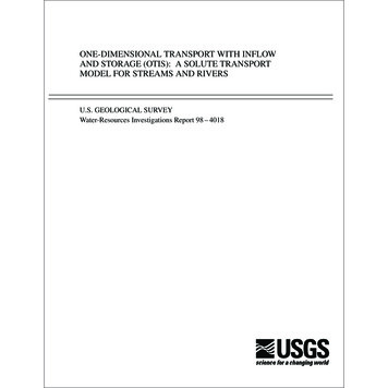
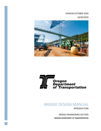
1. 2.1 Wood as an Engineering MaterialThe strength of wood is highly dependent upon the orientation of the appliedload in relation to the grain direction of the wood. This is one of the mostimportant characteristics of wood as an engineering material: the resistancesand the elastic properties of wood differ greatly in different directions, therebyclassifying wood as an anisotropic material.This characteristic is a direct result of the structure and chemical composition ofwood. Wood is composed mainly of tube like cells that are oriented vertically inthe stem of the growing tree. This orientation can also be thought of as thelongitudinal direction of logs taken from the harvested tree and as thelongitudinal direction of pieces of structural timber sawn from the logs. Wood ismuch stronger and stiffer in the longitudinal direction (or the grain direction)than it is perpendicular to the grain direction. This is primarily due to the tubesbeing inherently stronger and stiffer in their axial direction than in theirtransverse direction (Figure 1.2.1-1).The anisotropic nature of wood is accentuated by the presence of strong stiffcellulose microfibrils embedded in the matrix of the cell walls. The microfibrils,for the most part, are oriented nearly parallel to the axis of the cells. Thus, theyprovide additional longitudinal resistance in a manner somewhat analogous tothe role of steel bars in reinforced concrete.The shrinkage and swelling behaviour of wood due to moisture contentchanges is similarly anisotropic. Therefore, wood is much more dimensionallystable in the longitudinal direction (parallel to grain) thanin the transverse direction (perpendicular to grain).Section 15 of 43
Figure 1.2.1-1Anisotropic Nature of Wood1. 2.2 Timber Bridge (Types) SystemsThe following defines the timber bridge types, components and/or systemsspecifically covered by the subsequent sections in this manual, as well as somestructural systems which are common to more than one bridge type. In general,the examples given here relate to the more traditional or common styles.Additional details will be provided in the subsequent sections.This review provides a means for defining some of the accepted terminologywhich will be used throughout this manual. Words in italics are noted to be theaccepted terms normally used in the field when referring to the bridge type,components or system under consideration. These terms are defined inSubsection 1. 1.5.Section 16 of 43
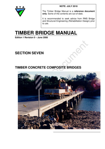
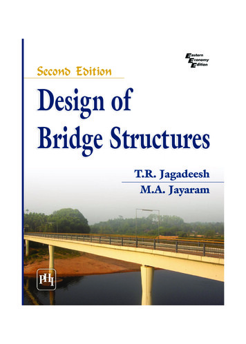
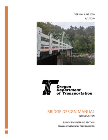
1. 2.2.1 Timber SubstructuresSection 2 covers timber substructures including timber piles, abutments(Figure 1.2.2.1-1) and piers, as well as all other components such as bracing,capwales and headstocks. Basically, the substructure includes all items belowthe main superstructure bearing points including the supports themselves.Figure 1.2.2.1-1Dungog Shire - Timber Pile Abutment1. 2.2.2 Timber SheetingSheeting is the top layer of a traditional timber bridge deck, whether it is on atruss (Figure 1.2.2.2-1) or a simple girder bridge. It is typically (but not limitedto) 50 mm to 75 mm thick running longitudinally. In some rare cases, sheetinghas been used diagonally (herringbone see Section 4).Sheeting is usually laid on top of closely spaced transverse timber decking (seeSubsection 1. 2.2.3) and can typically be found on: timber girder bridges timber truss bridges steel lift spansSection 17 of 43
Figure 1.2.2.2-1Clarencetown Bridge - Longitudinal Timber Sheeting1. 2.2.3 Timber DeckingTimber decking refers to closely spaced transverse timber planks(Figure 1.2.2.3-1) which are supported on longitudinal girders. This decking isusually up to 125 mm deep (200 mm to 250 mm wide) and directly supports thetimber sheeting. However, some bridges have larger size transverse decking atwider spacings as will be discussed in more detail in Section 4.Timber decking is usually supported on fairly closely spaced longitudinal girders(under 1.5 m spacing) and can typically be found on: timber girder bridges timber truss bridges steel lift spansFigure 1.2.2.3-1Section 1Anderson Creek - Timber Decking8 of 43
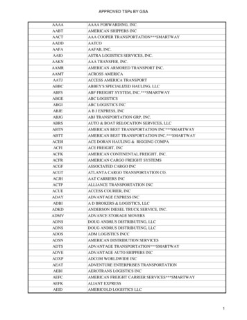
1. 2.2.4 Timber GirdersTimber girders are round, as shown in Figure 1.2.2.4-1, with timber corbels atpier supports. Combined with timber decking and sheeting, timber girders formthe most common timber bridge type. The latter combination is also frequentlyused as a deck system on larger structures such as timber trusses (and evensteel lift spans) and sometimes utilises square girders as will be outlined inSection 4.Figure 1.2.2.4-1Lignum Creek - Timber Girders1. 2.2.5 Timber Trusses (and Cross Girders)Section 3 covers timber trusses (Figure 1.2.2.5-1) along with the main timbercross girders shown in Figure 1.2.2.5-2. These members are generally seen asa separate class from the deck systems as they typically use larger sectionsizes and more durable materials.Figure 1.2.2.5-1Section 1Galston Gorge - Timber Truss9 of 43
Figure 1.2.2.5-2Wakool River - Timber Cross Girder1. 2.2.6 Stress Laminated Timber SystemsThe stress laminated timber (SLT) system, shown in Figure 1.2.2.6-1, is adevelopment which utilises thin (35 mm to 50 mm thick) timber laminates ofwidths from 140 mm up to 290 mm (and wider where manufactured timbermaterials are used). These laminates are oriented on edge (upright) andstressed together using high strength bars or prestressing strands to form asolid structural slab. There are an increasing number of bridges in NSW whichutilise the SLT system. Most of these bridges have simple slab decks.However, there are a few which have a more detailed (built-up or cellular)system. The latter are outlined in more detail in Section 5.Figure 1.2.2.6-1Section 1Bridge over Rail at Molong - SLT Hardwood Deck10 of 43
1. 2.2.7 Concrete OverlaysConcrete overlays (Figure 1.2.2.7-1) constitute a lightly reinforced (thin)concrete overlay placed on top of an existing timber girder bridge. These arenot made composite with the supporting timber members and are used tostiffen and strengthen the overall structural system. The timber girders, deckingand sheeting remain in place. More details are outlined in Section 6.Figure 1.2.2.7-1Corowa - Timber Girders with Concrete Overlay1. 2.2.8 Timber Concrete Composite SystemsThe timber-concrete composite system, shown in Figure 1.2.2.8-1, is also adevelopment now being increasingly used in NSW. The system was developedby the RTA in Grafton and utilises (round) timber girders. The decks aredesigned to span from 8 m to 12 m and are built in panels as shown in thefigure. Each panel usually has two timber girders which are made composite(using steel shear connectors) with a concrete deck.Figure 1.2.2.8-1Section 1Timber Concrete Modules During Load Testing11 of 43
1. 2.3 Traffic BarriersFigure 1.2.3-1Leycester Creek - Typical Timber Post, Rail and KerbIn general, the traditional traffic barriers, railing and kerbs used on timberbridges were not designed to meet any of the types of design loads in usetoday. The common form of timber post and railing, shown in Figure 1.2.3-1,was developed over the decades from tradition rather than design. The detailsvary very little from bridge to bridge and have been applied to timber girderbridges as well trusses.Currently, it is considered acceptable to repair an existing timber railing systemof this type using the same timber components. However, where a bridgeundergoes a major rehabilitation the traffic barriers must be upgraded to meetcurrent design standards. This necessity is derived from the increased liabilitythat the bridge owner faces from possible damages if the public is not properlyprotected.It should be noted that upgrading is not just simply a matter of facing theexisting post system with a new steel traffic rail or adding light steel posts suchas shown in Figure 1.2.3-2.Section 112 of 43
Figure 1.2.3-2Western Region - Light Steel Posts and Traffic RailIt is necessary to have a post and railing system engineered to meet theAustroads design loads and the design must specifically include the connectionto the bridge. These upgraded traffic systems can be quite costly, but it ispossible to meet the standards with minimum changes to the existing structure.1. 2.4 Wearing SurfacesExcept with the newer SLT bridges and the timber-concrete composite designs,the traditional timber sheeting decks use only a thin flush seal surface(Figure 1.2.4-1). While this seal does not waterproof the entire deck system, itprotects the sheeting from rapid drying which can cause splitting, checking andgeneral deterioration. It also provides a safer surface by providing bettertraction for vehicles.Section 113 of 43
Figure 1.2.4-1Grafton Region - Flush Seal on Timber SheetingGenerally, the new timber-concrete composite decks and concrete overlays donot have a wearing surface applied and vehicles travel directly on the concrete.Additional information on these bridge types is provided in Sections 6 and 7.The new SLT bridges require both a waterproofing system as well as a wearingsurface. Since the SLT system provides a strong and stiff structural slab, thesedecks can support any bitumen based wearing surface without cracking.Additional information is provided in Section 5.1. 3INSPECTION PROCEDURESThe following outlines the basic procedures applying to the inspection of alltimber bridge types and components. The subsequent sections provideadditional information for the specific bridge types and/or components coveredby that section.1. 3.1 ObjectivesThe general objectives of inspection shall include: to determine the effectiveness of past maintenance activitiesnote the changes in the state of previously reported problem areasto identify problem areas which require maintenance and/or repairto identify potential problems that could advance and lead to the need formaintenance in the futureSection 114 of 43
1. 3.2 General RequirementsThe general requirements for inspection shall include: integration of inspection and maintenanceutilisation of experienced personneluse of consistent inspection methods as well as terminologiesmaintenance of detailed inspection recordsreview of past inspection records prior to inspectionon site use of past inspection records1. 3.3 Inspection RecordsDetailed inspection records must be maintained for all inspections and theserecords shall be used as the basis for both maintenance works and futureinspections. The records shall include, but not be limited to, the following: meticulous and detailed observations using quantitative information (eg:amount of pipe and/or rot from boring, % loss of protective coatings) supplementation of specific problem areas using photographs the use of consistent forms, diagrams and terminologies the use of consistent methods of inspection1. 3.4 Types and Frequency of InspectionsTwo types of inspection shall be performed on a regular basis. Visualinspections shall be performed annually and shall be supplemented with moredetailed inspections every three years.Specific problems, remedial repairs and/or other specific considerations shouldbe monitored, as required, to ensure the integrity and safety of the structure ismaintained.1. 3.5 Visual InspectionVisual inspections should be conducted together with the annual maintenanceworks. The latter are outlined in Subsection 1. 4.Visual inspections shall include: all exposed timber bridge components including the substructureobservation of the bridge under transient loadingidentification of any obvious structural defects and damageidentification of any obvious deteriorationspecific attention to previously reported problem areas in past inspectionrecordsSection 115 of 43
1. 3.5.1 Inspection Under Transient LoadingVisual inspection of the bridge under transient loading shall include: the use of experienced personnel the use of a reasonably heavy vehicle so that movements are well defined the use of a specific vehicle, where possible, to provide more consistency inthe bridge movement for comparative purposesThe observations and records should include: all components and connections including the substructure and thesuperstructure overall deformations as well as local movements under the wheel loads vertical deflections in girders, cross girders and other flexural members, aswell as trusses any movements of piles and other substructure components descriptive written record of any apparent problem areasSpecific attention should be given to: apparent excessive movements, as compared to the majority of othercomponents inconsistent or uneven performance movements at joints and connections known problem areasSpecific considerations for the different bridge types and components areoutlined in subsequent sections.1. 3.5.2 Structural Damage and DefectsAll components and connections shall be inspected for obvious structuraldefects and damage caused by loading or collisions. These should include: fractures due to loading, particularly in flexural (bending) memberslocal crushing at bearings, including the ends of truss memberspropagation (or extension) of the natural end splits in flexural membersloose connections, including local crushing of timber and/or enlarged holesaround bolts collision damageSome critical areas to be inspected for different components and structuretypes are highlighted in subsequent sections.1. 3.5.3 Timber DeteriorationSection 116 of 43
There are four types of timber deterioration; decay (or fungal attack), insectattack, weathering and fire damage which are all discussed in detail inSection 8. In summary, only decay and insect attack represent a significantdanger to timber bridges. Section 8 should be read prior to performing siteinspections.All timber components shall be inspected for deterioration caused by decayand/or insect attack. These should include: sapwood in all componentsground contact areas, such as piles, and abutment componentsareas where water is trapped or does not dry out readilyinterfaces between componentsholes at connectionsends of members, particularly girders, piles and truss membersunder flashingbehind other protective coatings, particularly paintSome critical areas to be inspected for different components and structuretypes are highlighted in the subsequent sections.1. 3.5.4 Summary of Visual InspectionThe following is a summary of the basic requirements for the annual visualinspection of timber bridges: inspection should be integrated with routine maintenanceprevious inspection records should be used on sitethe bridge should be observed under transient loadsall exposed areas of all components should be inspected for structuraldamage, defects and deterioration connections and their components should be inspected for signs oflooseness or damage attention should be given to previously reported problem areas detail records and photographs should be produced1. 3.6 Detailed InspectionIn addition to the annual visual inspections, a more detailed inspection must becarried out every three years. This inspection should include: integration of the inspection with the three year maintenance activitiesoutlined in Subsection 1. 4 extending visual inspection to hidden areas exposing questionable areas, particularly between components and buriedportions of the substructure boring of main structural components as outlined in Subsection 1. 3.7Section 117 of 43
Some critical areas to be inspected for different components and structuretypes are highlighted in subsequent sections.1. 3.7 Boring
This manual is intended to replace all existing RTA/DMR publications concerning timber bridge maintenance, including ‘Manual No. 6 - Bridge Maintenance’ (DMR, 1962 and re-issued 1983) and to complement the ‘Timber