Transcription
1Basic User ManualMaxwell 2DStudent VersionRick HoadleyJan 2005
2Overview Maxwell 2D is a program that can be used tovisualize magnetic fields and predict magneticforces. Magnetic circuits are difficult to design because thematerials used are non-linear and the fields can notbe confined like electrons within wires. This program makes the design process mucheasier.
3Steps (1-4)These are the eight steps in designing andanalyzing a magnetic circuit.1. Open a project (set up the file name and type ofproblem)2. Define the model (draw the items in the circuit)3. Setup the materials (specify what each item ismade of)4. Setup boundaries and sources (specify whathappens outside the window you are looking at,and specify any currents that are flowing withinany item)
4Steps (5-7)5. Setup executive parameters (are there forces ortorques you want to have calculated?)6. Setup solution options (determine how accurateyou need your answers, because the solution isiterative in order to get closer and closer to thefinal answer.7. Solve the problem (uses automatic meshing andfinite element analysis to solve the problem)
5Steps (8-9)8. Post Process (look at the solution to the problem.This can be a plot of any of the following:––––––––Flux linesMagnitude or vector of BMagnitude or vector of HMagnitude or vector of JEnergyTorqueForceetc )9. Exit Maxwell
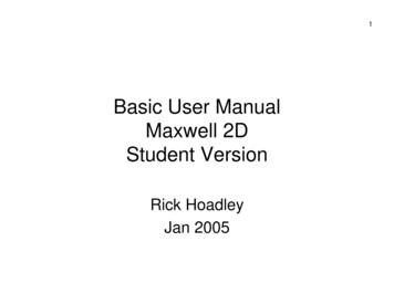
6Example The best way to learn this is to try an exampleyourself. I would suggest that you make a copy of thisdocument in order to follow along as you workthrough the example. The next page shows what we will create and thenproduce a plot of the flux lines and a plot of the fieldstrength.
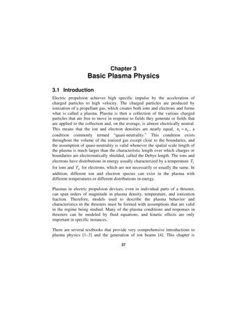
7Layout of nless SteelplateNOTES:1. The North pole for Magnet1 is in theupper right hand corner.2. The North pole for Magnet2 is at the top.
8Field Lines of Example
9Download & Install Let’s get started. You need todownload andinstall Maxwell 2DSV (studentversion) onto yourcomputer. It canbe found at:http://www.ansoft.com/maxwellsv/
10System Requirements You need to haveWindows NT or2000 or XP inorder to run thisprogram. Windows 98SEmight work, butthere is noguarantee norsupport.
11Sample Projects Don’t forget to alsodownload theirGetting StartedGuides andSample Projects. These guides area little moreadvanced than thisBasic UserManual. They willhelp you work onother problems.
12Users Be sure you meetthe criteria theyrequire for a freecopy of thisexcellent program. The download sizeis about 36MB –so use a highspeed internetconnection!
13Step 1a On your desktop is the icon for this. Double click the icon to start the program.
14Step 1b This is the main toolbar. Click on [PROJECTS].
15Step 1c This is where youmanage yourMaxwell projects. Click on [New ].
16Step 1d This is where you enterthe project name. Type “test001” in for the‘Name:’ as shown in thelower screen shot. Make sure there is acheck mark for ‘Openproject upon creation’. Then click [OK].
17Step 1e This is the screenyou use to createthe details of themodel. Along the left handside are the stepswe will follow inorder from top tobottom.
18Step 1f Set the type ofsolver to be“Magnetostatic” Set the drawingcoordinate systemto be “XY plane”
19Step 2a Now we draw theobjects. Click on [DefineModel]
20Step 2b This is the newscreen and set oftools you get afteryou click on[Define Model] This is where youdraw the magnetsand other objects
21Step 2c The tools are basicdrawing tools.We’ll use therectangle drawingfunction. After clicking onthe rectangle in thetoolbar, go to thescreen and clickthe top left cornerfor the magnet. Then click thelower right cornerto complete themagnet.
22Step 2d After you draw anobject, this windowappears. It asksyou for a name ofthe object andwhat color youwant it to be. We will leave thename as “object1”and leave the coloras red. Click [OK].
23Step 2e Use the same toolto draw thisrectangle. The name will be“object2”. Make the colorgrey.
24Step 2f Use the same toolto draw thisrectangle. The name will be“object3”. Make the colorgreen.
25Step 2g Use the same toolto draw thisrectangle. The name will be“object4”. Make the colorgreen.
26Step 2h Use the same toolto draw thisrectangle. The name will be“object5”. Keep the color red.
27Step 2i To exit thiswindow, go to File,Exit. When the smallwindow appears,click on [Yes].
28Step 3a This brings youback to thisscreen. Noticethat there is acheck mark to theright of [DefineModel], since thatstep has beencompleted. Now, click on[Setup Materials ]
29Step 3b This screen allowsyou do define whatmaterial eachobject is made of.
30Step 3c Click on ‘object1’in the Objectsection. This willcause double linesto outline thedrawing of theobject. Then find and clickon ‘NdFe30’ in theMaterial section. Click on [Assign].
31Step 3d A new windowappears. This iswhere you specifywhat direction thefield from themagnet is pointing.
32Step 3e Click on ‘Align witha given direction” Fill in “45” for theangle Remember that 0degrees points tothe right, 90 degpoints up, 180 degpoints to the left,and 270 deg pointsdown. Click on [OK]
33Step 3f You now see thatNdFe30 has beenassigned theMaterial for‘object1’ in theObject section. We need to dosimilarassignments forthe other objects.
34Step 3g Click on ‘object5’ Click on ‘NdFe30’ Click on [Assign]
35Step 3h Click on ‘Alignwith a givendirection’ Fill in 90 for thedegrees angle Click on [OK].
36Step 3i Click on ‘object2’
37Step 3j Click on‘steel 1008’ Click on [Assign]
38Step 3k Click on ‘object3’
39Step 3l Click on‘aluminum’ Click on [Assign]
40Step 3m Click on ‘object4’
41Step 3n Click on‘steel stainless’ Click on [Assign]
42Step 3o Click on [Exit] This smallconfirmationwindow appears. Click on [Yes]
43Step 4a We are back tothis window. Note the checkmark next to the[Setup Materials ] Click on [SetupBoundaries /Sources ]
44Step 4b This is where wespecify whathappens outsidethe big red boxand if there is anycurrent flowing inany object.
45Step 4c Click on Edit,Select, Object, ByClicking Then, take thepointer and click itonto the redboundaryrectangle. Youmay have to be alittle bit to the leftor right. After that, rightclick your mouse.
46Step 4d Click onto theballoon button.
47Step 4e Click onto the[Assign]
48Step 4f The outside redrectangle has nowbeen assigned asa balloon, meaningthat it is like thereis no boundarythere at all –however, thesolutions will notbe accurateoutside the redrectangle.
49Step 4g Simply click onFile, Exit, and[Yes] in theconfirmationwindow.
50Step 5a There is now acheck mark next to[Setup Boundaries/ Sources ] We do not need todo anything with[Setup ExecutiveParameters]
51Step 6a Click on [SetupSolutionOptions ]
52Step 6b This windowappears.
53Step 6c I usually set the‘Percent error’value to 0.001. This will cause thesimulation to runlonger, but the fluxlines will be muchsmoother. Click on [OK]
54Step 7a There is now acheck mark next to[Setup SolutionOptions ] Last big step is tonow solve theproblem. Click on [Solve]
55Step 7b While the programis solving theproblem, you willsee the SolutionMonitoringwindow. The redbar in the windowwill go to 100several times as itis working on thesolution.
56Step 7c Finally, thiswindow will pop upsaying that thesolution iscomplete. Click on [OK]
57Step 8a There is now acheck mark next to[Solve] In order to see theresults, click on[Post Process ]
58Step 8b This is a newwindow that willshow us theresults and all thecool stuff you wantto see.
59Step 8c Click on theCoordinates buttonthree times tochange the look ofthe axis and toremove them.
60Step 8d Click on the Fillbutton to turn thefill on or off. I likeit on, so theobjects will besolid and not justoutlines.
61Step 8e Click on Plot, Fieldto bring up thiswindow to selectwhat you want toplot.
62Step 8f Click on ‘FluxLines’ in the lefthand column Click on ‘Surface –all-’ in the middlecolumn Click on [OK]
63Step 8g This window asksfor moreinformationregarding what youwant the plots tolook like.
64Step 8h I usually turn offthe ‘Show colorkey’ Then I increasethe ‘Divisions’ to30 (better if it is aneven number) Click [OK]
65Step 8i There! You nowhave a plot of theflux lines due tothe arrangement ofobjects youdefined. But wait! There’smore!
66Step 8j It is easy to zoominto the plot inorder to see whatis going on indifferent places. Simply click on the‘Magnify’ button,click at the upperleft corner of whatyou want to fill thescreen, then clickat the lower rightcorner.
67Step 8k If you want to seesome other kind ofplot, click on Plot,Delete This window willshow you what ispresently beingdisplayed.
68Step 8l Click on the plotthat you wanterased from thescreen to highlightit. Click on [OK]
69Step 8m Click on [Yes]
70Step 8n You are back to aclean screen.
71Step 8o Let’s look at themagnetic field thatis present aroundthe objects. Click on Plot, Field Click on ‘Mag B’ inthe left handcolumn Click on ‘Surfacebackground’ in themiddle column Click on [OK]
72Step 8p Leave everythingas it is. Click [OK]
73Step 8q Now you see howthe magnetic fieldis spread outaround the objects. The key showshow to interpretthe colors withrespect to themagnetic fieldstrength, in units ofTesla.
74Step 8r You can zoom intothis the same wayas before.
75Step 9a What do you do ifyou now want toexit the Maxwellprogram? First, close thisscreen by clickingon File, Exit. Then click [Yes] inthe confirmationwindow.
76Step 9b Click on [Exit]
77Step 9c Click on [Yes] inthe confirmationwindow.
78Step 9d Before you leave,you can click on aproject name andsee a roughpicture of it in thewindow. Since this is new,you may need toclick on a differentproject name andthen back to thisone.
79Step 9e Click back onto‘test001’ and youwill see the objectsof this project inthe window. Thishelps you find aproject you may belooking for. To continue to exitthis program clickon [Exit]
80Step 9f Click on [Exit] in thetop bar Click [Yes] in theconfirmation window That’s all, folks!
Basic User Manual Maxwell 2D Student Version Rick Hoadley Jan 2005. 2 Overview Maxwell 2D is a program that can be used to visualize magnetic fields and predict magnetic forces. Magnetic circ