Transcription
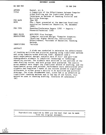
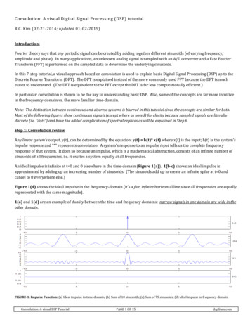
Two-Dimensional Convolution on the SCCDavid W. IlligChen LiuDepartment of Electrical and Computer EngineeringClarkson UniversityPotsdam, NY 13699, USA{illigdw, cliu}@clarkson.eduAbstract—Convolution is one of the most widely used digitalsignal processing operations. This work aims to distribute twodimensional convolution operation across Intel’s Single-ChipCloud Computer (SCC), an experimental processor created byIntel Labs. This platform enables experiments with varying boththe data sizes and the physical parameters of the platform such asvoltage, frequency, and number of cores. The program can also beoptimized subject to power and energy considerations. We findthat implementing the convolution operation on the SCC canreduce the calculation time but results in a communicationbottleneck. We find that calculations should be run at a lowerfrequency to reduce energy consumption, while communicationsshould be run at a higher frequency to reduce execution time.Current applications are in the area of early vision using aGaussian pyramid, while we aim to expand the study to additionalimage processing areas.of the Linux operating system. RCCE is built similarly to themessage-passing interface (MPI) and OpenMP with functionscustomized for the SCC. RCCE provides utilities forcommunication, synchronization, memory management, andpower management [4]. Power management is done by settingthe frequency and voltage. As shown in Figure 1, the granularityfor frequency changes is one tile, while the granularity forvoltage changes is eight cores and is called a power domain. The48 cores are divided into six power domains labeled from 0 to 5;note that the logical numbering of cores does not follow thepower domain distribution. In total there are 69 frequencyvoltage combinations, or “gears”, possible on the SCC. Thiswork will use a very small subset of gears for proof of conceptpurposes.Keywords—Convolution; SCC; FFT; Parallelism; DVFSI.INTRODUCTIONConvolution is a widely used operation in image processing,including applications such as smoothing, blur removing,filtering, and edge detection. In all of these operations, a filterkernel is convolved with an image matrix that is typically muchlarger than the kernel. Performing a convolution operation in aparallel fashion should allow for reduced execution time hencebetter performance.The Single-Chip Cloud Computer (SCC) experimentalprocessor [1-3] is a 48-core ‘concept vehicle’ created by IntelLabs as a platform for many-core software research. The SCCcombines 48 P54C Pentium processor cores on a single chip.The 48 cores are placed in a tile formation, with two cores pertile. A single router is shared by the cores on a tile, which isconnected to an on-die mesh network. The tiles are arranged ina 6 4 mesh, as shown in Figure 1. Each core has a private oncore L1 cache with 16 KB of data and 16 KB of instructionstorage. Each core also has a private on-tile, unified L2 cachewith 256 KB of storage. Each tile has a 16KB block of SRAMorganized onto a shared address space visible to all cores on thechip. This memory is called the “message-passing buffer”(MPB), as it is a communication buffer that supports themovement of L1 cache lines between cores. The 64 GB off-chipDRAM is divided into memory regions that can be either privateto each core or shared by all cores.Intel provides a small, customized message-passing libraryfor the SCC called RCCE [4, 5]. Program execution begins on asecond machine called the management console PC (MCPC),which then issues commands to load programs onto individualcores on the SCC. The MCPC and the SCC cores all run versionsFigure 1. SCC Layout (modified from [4])This work focuses on distributing the convolution operationacross the 48 cores of SCC. The program can be optimizedsubject to power and energy constraints as well via SCCplatform. Due to the novel status of the SCC, there is very littlecomparable work that has been published at present on the SCC.Wang et al. explored the parallelism of Fast Fourier Transform(FFT) on the SCC [6]. As our convolution approach will alsouse the FFT, there is some common ground. They found thatthey can achieve significant performance improvement bydividing the FFT task across multiple cores, up to 25 timesspeedup when using 32 cores. However, they do not perform anypower or energy analysis. Additionally, their FFT algorithmrequires that cores communicate during every transformoperation due to a need to share data, while the approach we take
will distribute data such that cores work on independent datasegments.The parallelism of the FFT has been well studied on severalother hardware platforms, many of which use more sophisticatedhardware than the SCC. Sapir implemented a distributed FFTalgorithm on a 16-core Epiphany Network-on-Chip (NOC)processor, finding that this particular NOC was limited to amaximum image size of 128 128 and that almost 90% of theexecution time was spent on the butterfly stages of the FFT [7].Although the SCC has more cores that each have more memorythan those of the Epiphany NOC, there is still some similarity inthat our approach decomposes the image matrix in a similarmanner to Sapir’s approach. Bahn et al. developed three parallelFFT algorithms that they tested on a simulated NOC usingSystemC, concluding that the algorithm with the most balancedwork load and least communication overhead allowed for fastestcomputation of the FFT [8]. Our approach is similar in that weattempt to minimize communication and ensure that all coreshave the same amount of data to work on during parallelcomputation steps. Moreland et al. explored distributing the FFTon a commodity graphics processing unit (GPU) [9]. As the SCCis based on older Pentium processors, it is difficult to make a faircomparison to performance achieved by a GPU, though it maybe of interest to adapt certain aspects of Moreland’s algorithmfor the SCC. Pippig developed an MPI-based library forcomputing the FFT of multidimensional matrices which wastested on three supercomputers at the Jülich SupercomputingCenter, showing scalability for large number of cores superiorto previous FFT libraries, while also analyzing the percentage ofexecution time spent on communication and computation steps[10]. While Pippig’s use of supercomputers with thousands ofcores and more than 0.5 GB of memory per core prevents anyfair comparison to the SCC’s capabilities, the execution timetrends observed may provide insight into how the SCC mightperform as number of cores or matrix size is increased.The rest of this paper is organized as follows: Section IIprovides some background material on the convolution; SectionIII describes our algorithm and data collection methodology;Section IV presents experimental results; Section V discussesthe results and experience of using our algorithm on the SCC aswell as raising areas of future work and application; Section VIprovides a conclusion summarizing the work.The convolution requirements can be greatly reduced bytaking advantage of the properties of the Fourier Transform.The Fourier Transform of a two-dimensional matrix is given bythe following integrals, with Equ. 2 giving the forwardtransform and Equ. 3 giving the inverse transform [13]:𝐺 (𝑎, 𝑏) 𝑔(𝑥, 𝑦) exp( 𝑗2𝜋(𝑎𝑥 𝑏𝑦)) 𝑑𝑥 𝑑𝑦(2)𝑔(𝑥, 𝑦) 𝐺 (𝑎, 𝑏) exp(𝑗2𝜋(𝑎𝑥 𝑏𝑦)) 𝑑𝑎 𝑑𝑏(3)Throughout the remainder of the paper, we will use the symbolFT{X} to represent taking the Fourier Transform of matrix X,and the symbol FT-1{X} will represent taking the InverseFourier Transform of the matrix X.The Fourier Transform of a convolution is equivalent to theproduct of the Fourier Transforms of the two input matrices[12]. This will allow us to calculate the convolution of twomatrices using the following equation:𝐻 𝐹 𝐺 𝐹𝑇 1 {𝐹𝑇{𝐹 } 𝐹𝑇{𝐺}}Using the definition of the Fourier Transform, this approach hasa run-time of 𝑂(𝑁 2 ) . However, the Fast Fourier Transform(FFT) can be used to improve the run-time performance to be𝑂(𝑁 log 𝑁). For sufficiently large matrices, the overhead fromcomputing the FFT will be insignificant compared to theperformance improvement versus calculating convolutiondirectly from its definition.A final property used to improve performance in this studyis that the Fourier Transform is a separable operation [13,15].That is, a multi-dimensional Fourier Transform can beseparated into a series of one-dimensional Fourier Transforms.This can be derived from Equ. 2, as the exponential functioncan be split into independent functions of x and y, allowing forintegration along the x-dimension to be performedindependently of the y-dimension. The benefits of this relationare two-fold. First, we need only implement a one-dimensionalFourier Transform to perform the convolution. Second, as eachone-dimensional transform will work with less data than amulti-dimensional transform, we would expect the onedimensional transforms to complete faster.III.II.BACKGROUNDThis section will provide a brief overview of themathematical foundations relevant to this work. We will give ahigh-level overview of the mathematical definitions andproperties used to implement this study.Two-dimensional convolution of N N matrices F and G isdefined by the following integral [11-13]:𝐻 𝐹 𝐺 𝑓 (𝑎, 𝑏)𝑔(𝑥 𝑎, 𝑦 𝑏) 𝑑𝑎 𝑑𝑏(1)To calculate one entry in the convolution matrix H, due to theshifting operation of the convolution, the corresponding entryin the matrix F must be multiplied by all N2 elements of thematrix G. These products must be added together to obtain thefinal result. This process must be repeated for each of the N2elements of F to compute the remaining entries of H [14].(4)METHODOLOGYThis section will discuss the methodologies and algorithmused in this work. The algorithm design will be presented,followed by discussion of how certain aspects of the algorithmwill be implemented on the SCC. This will be followed by abrief overview of the measurement and calculation schemesused to assess this work.A. Algorithm DesignThe algorithm developed for this study is an attempt tobalance some known improvements for computing twodimensional convolution alongside the specific attributes of theSCC. A pseudo-code representation of the algorithm ispresented in Figure 2.
1.2.3.4.5.6.7.8.9.10.11.12.13.14.15.Load A and B from memoryPartition A and B across N coresEach core calculates row FFT of 1/N rows of A and BAssemble 𝐶 𝐹𝑇{𝐴} and 𝐷 𝐹𝑇{𝐵}Compute transpose 𝐸 𝐶 𝑇 and 𝐹 𝐷 𝑇Partition E and F across N coresEach core calculates row FFT of 1/N rows of E and FEach core calculates 1/N rows of complex multiplication 𝐺 𝐸 𝐹Each core calculates row IFFT of 1/N rows of GAssemble 𝐻 𝐹𝑇 1 {𝐺}Compute transpose 𝐼 𝐻Partition I across N coresEach core calculates row IFFT of 1/N rows of IAssemble 𝐽 𝐹𝑇 1 {𝐼}Save J to memoryFigure 2. Pseudo-code of Convolution AlgorithmThe algorithm consists of eight repeated steps, which we willrefer to as the program phases; these have been highlighted inbold in Figure 2. Note that due to the use of the FourierTransform, all matrices are complex data, which we representusing one matrix to store the real part and another to store theimaginary part. This program is a mixed workload consisting ofsome sequential steps and some parallel steps. We use Core 00of SCC to control the process and perform the sequentialoperations of file input/output, partition, assemble, andtranspose operations. In the partition operation, Core 00 usesmessage-passing to send sub-matrices to the other cores, whilein the assemble operation the other cores send their submatrixresults to Core 00. Forward and inverse Fourier Transforms aswell as the complex multiplication are distributed across allcores involved in program execution. As discussed previously,we implement a one-dimensional Fourier Transform. Bytransposing the matrix after a row transform, we are able to usethe same code to process the columns, as in [15]. By sending anentire row of data to each participating core, the core has all thedata it needs to perform the transform and thus does not need tocommunicate with any other cores while performing thecalculation. All phases use custom implementations of thedesired operation. The FFT and IFFT implementations use aniterative version of the Cooley-Tukey algorithm [16], whichwas adapted for the SCC from a version presented in [17].Table 1. Gear SettingsGearIdleLowHighVoltage0.8 V0.8 V1.1 VFrequency200 MHz533 MHz800 MHzIn addition to the message-passing interface, other SCCfeatures are taken advantage of in this study as well. The mostobvious one is the distribution of calculation steps acrossmultiple cores. Cores are assigned not based on their numericalnumbering, but based on their physical location in order tominimize the number of power domains used in each operation,in reference to Figure 1. We utilize three gear settings fortesting our program on the SCC, where each gear is a distinctcombination of voltage and frequency settings. Cores that arenot active are placed in a low-power, idle state. In addition,execution is tested using high and low power gears, as shownin Table 1. Power domains are set statically at the start ofprogram execution.B. Data CollectionFor this study, both execution time and average power datawere collected for each program phase as well as for the entireprogram. Execution time was measured after every phase of theprogram as well as at the end of the SCC program, using theRCCE timing function [4]. Power measurement was done in thestandard way for the SCC presented in [18].From the execution time and average power measurements,energy consumed by the SCC can be estimated. The energy wascalculated as the product of total execution time and averagepower:𝐸 𝑇𝑒𝑥𝑒𝑐 𝑃𝑎𝑣𝑔(5)In addition to calculating the energy consumption with Equ. 5,we are also able to compute the energy-delay product (EDP).EDP is a metric that incorporates information about both theexecution time and energy consumption of a program, which isa balanced measure of both the response time from the userpoint of view and energy saving from the system point of view.EDP is calculated as the product of energy and total executiontime:𝐸𝐷𝑃 𝑇𝑒𝑥𝑒𝑐 𝐸 (𝑇𝑒𝑥𝑒𝑐 )2 𝑃𝑎𝑣𝑔(6)Beyond analyzing the complete program, we were also able tocalculate the energy and EDP consumed by each program phaseby measuring the execution time and power consumed by eachphase and applying Equ. 5 and 6 to each phase.The program was tested for matrices of representative sizesof 64 64 and 128 128. These sizes were felt to be reasonableto represent large image processing filter kernels. The programwas also tested using various numbers of cores to explore thetradeoffs between parallel calculation and the overhead fromthe increased communication required as the number of coresincreases.IV.RESULTSFirst, results for the entire program will be presented. Thiswill be followed by a presentation of results for specific phasesof the program. The program was tested with configurationsusing 1, 2, 4, 8, 16, 32, and 48 cores.A. Results for Entire ProgramExecution time, power, energy, and EDP trends werecalculated for the entire program as a function of the matrix sizeas well as the number of cores. The trends for the low gearsetting are shown in Table 2 and Table 3 for the 64 64 and128 128 matrices, respectively; while the higher gear data forthe 64 64 matrix is shown in Table 4 with the 128 128 matrixresults in Table 5. As would be expected, in an identicalconfiguration the high gear has better execution time, while thelow gear has the better power reading. The results also showevidence of a communication bottleneck, indicated by the trendfor execution time to increase as the number of cores increases.
In the absence of communication delays, we would expect thatincreasing the number of cores would reduce execution time.This issue will be discussed in more detail in the followingsubsection.Different trends are observed for energy and EDP. For thesmaller matrix size of 64 64, the lower gear always consumesless energy. In terms of EDP, the lower gear is slightly betterwhen using a single core, while the reduced execution time ofthe higher gear results in better EDP reading when usingmultiple cores. For the larger matrix size of 128 128, the lowergear has better energy performance except when all 48 coresare active, at which point the higher gear consumes less energy.For the 128 128 matrix, the EDP performance is typicallybetter with the higher gear. An exception occurs for the 16-corecase, where the EDP of the lower gear is 1.3 J s less than thehigher gear scenario. In general, the reduced execution time ofthe higher gear allows for optimization of EDP performance,while the reduced power consumption of the lower gear allowsfor optimization of energy consumption.B. Results for Program PhasesFor each program phase, the percentage of total executiontime spent in that phase was calculated. Performance trends forenergy and EDP were also calculated for each phase. Theprogram phases can be grouped into three categories: Communication phases consisting of partition andassemble;Calculation phases consisting of FFT, transpose,multiply, and IFFT;File input/output phases consisting of load andsave.Table 2. Low gear performance on 64 64 matrixCores1248163248𝑇𝑒𝑥𝑒𝑐 (s)0.280.370.460.600.831.292.39𝑃𝑎𝑣𝑔 (W)28.2028.3228.1629.9031.8536.3536.68𝐸 (J)7.8610.4112.9217.7326.3746.8990.14𝐸𝐷𝑃 (J s)0.590.911.623.6310.1443.88185.75Table 3. Low gear performance on 128 128 matrixCores1248163248𝑇𝑒𝑥𝑒𝑐 (s)1.121.431.792.302.695.2212.25𝑃𝑎𝑣𝑔 (W)28.1428.2728.5629.8631.7336.4136.78𝐸 �� (J s)11.8615.3325.5354.76132.61619.823013.46Table 4. High gear performance on 64 64 matrixCores1248163248𝑇𝑒𝑥𝑒𝑐 (s)0.250.270.330.430.610.971.54𝑃𝑎𝑣𝑔 (W)46.4348.0649.2352.9359.4771.8373.44𝐸 � (J s)0.770.821.453.3110.0342.10136.30Table 5. High gear performance on 128 128 matrixCores1248163248𝑇𝑒𝑥𝑒𝑐 (s)0.831.021.251.612.253.635.66𝑃𝑎𝑣𝑔 (W)46.3548.1249.3752.8759.5271.9173.53𝐸 ��� (J s)10.1312.8821.7645.98133.92583.541816.03As a representative example, the percentage of executiontime for each phase for the high gear operating on the 128 128matrix is shown in Table 6. The trends for the otherconfigurations are very similar to this example, which would beexpected as the percentage of execution time should beindependent of the gear setting. Several interestingobservations can be made from the data in Table 6. For a smallnumber of cores, the file input/output operations occupy themajority of the execution time. As desired, the execution timespent on the calculation steps decreases as the number of coresis increased. The communication phases of partition andassemble dominate execution time when 4 or more cores areused for this application. In particular, the partition stepconsumes at least 50% of execution time for 8 or more cores,as execution is essentially halted until Core 00 has been able todistribute all of the data to the other cores. From anotherperspective, for 8 or more cores, the parallel calculation stepsoccupy 1% or less of the execution time. This suggests that theprogram is not utilizing the message-passing architecture aswell as it could be, as the current implementation results in acommunication bottleneck which dominates execution time.This is in contrast to Pippig’s algorithm, where messagepassing was used without any significant communicationbottleneck [10]. Alternative communication approaches arediscussed in Section V as a possible area of future work.Table 6. Percentage of Execution Time for Phases at High 2.2013.843.730.121.2838.36Number of Cores481610.958.526.2637.77 49.45 63.150.920.660.1614.51 12.839.972.992.321.670.050.030.010.550.500.1132.27 25.71 18.66323.8077.190.066.271.02 0.010.0511.60482.4785.780.034.120.66 0.010.026.92
The energy and EDP trends are summarized for each of thethree categories of phases: communication, calculation, and fileinput/output. As before, the high gear always optimizesexecution time for a given phase, while the low gear alwaysoptimizes power consumption. The high gear energy and EDPhave been normalized against the low gear energy and EDP forcomparison purposes in this section. That is to say, relativevalues less than one indicate that the high gear has betterperformance, while values greater than one indicate that the lowgear has the better performance. The relative energy and EDPtrends for the 64 64 matrix are shown in Figure 3 and Figure4, respectively, with the trends for the 128 128 matrix shownin Figure 5 and Figure 6, respectively.when 32 or 48 cores are used. This is believed to be due to thefact that while Core 00 is performing the file operations, theother cores are essentially doing nothing and should be set intothe lowest possible gear in order to reduce power consumption.Figure 5. Relative energy trends for 128 128 matrixFigure 3. Relative energy trends for 64 64 matrixFigure 6. Relative EDP trends for 128 128 matrixFigure 4. Relative EDP trends for 64 64 matrixFor the 64 64 matrix, energy consumption in every phase isminimized by using the lower gear, similar to the resultobserved across the entire program. In order to minimize EDPfor a 64 64 matrix, from Figure 4 it appears that the low gearshould be used for all calculation steps with the high gear usedfor all communication steps. This makes intuitive sense giventhat the communication steps are consuming the majority of theexecution time and thus contribute more significantly to theEDP than any other phase. The file input/output phases for the64 64 matrix follow a more complicate pattern, in which EDPis minimized by using the low gear for a single core as well asThe results for the 128 128 matrix are similar, with energyalmost always minimized by using the low gear as shown inFigure 5. An exception occurs for the file input/output phasewhen using 48 cores; this exception requires furtherinvestigation. The EDP trends for the 128 128 matrix shown inFigure 6 are also similar to the 64 64 matrix trend, with EDPof communication phases minimized in high gear andcalculation phases minimized in the low gear. With theexception of the 16-core case, the EDP of the file input/outputphases is also minimized in the high gear. This implies that fora larger matrix size, the reduced execution time from operatingin the higher gear has more of an impact on the EDP than theincreased power consumption. The 16-core case requiresfurther investigation to determine why there is such a dramaticincrease in the EDP.
V.DISCUSSIONIn this section implications of the preliminary results will bediscussed. Following this, a few areas for potential future workwill be described. Finally, a possible application for this studywill be presented that is tolerant of the current limitations.A. Optimal ConfigurationsThis subsection will briefly present the optimalconfigurations determined from the data collected for both theentire program and the different program phases. When lookingat the entire program, in order to minimize energy consumptionit is typically best to run in the low gear. An exception occurswhen using 48 cores to process 128 128 matrices. On the otherhand, when attempting to minimize EDP it is best to run in thehigh gear. The case of 16 cores operating on a 128 128 matrixoffers an exception where the EDP of the high gear isapproximately the same as the EDP of the low gear. Thesetrends show that the increased power consumption of the highgear drives up its energy consumption, while the reducedexecution time allows for a reduction in EDP.The results for the individual program phases can also beused to optimize performance in terms of energy or EDP. Ingeneral, the low gear should be used on all phases in order tominimize the energy consumption. The EDP performancefollows a more complicated pattern. The communicationphases of partition and assemble should always be run in thehigh gear in order to reduce EDP; this suggests that thereduction in execution time of these phases is much moresignificant than their increased power consumption. Thecalculation phases require such a small percentage of theexecution time that they can be run in the low gear in order tominimize EDP, showing that the power consumption is a moreimportant consideration for the calculation phases than theexecution time. Finally, the EDP trend for the file input/outputphases follows a slightly more complicated trend. The low gearminimizes EDP for the file input/output phases using a 64 64matrix when the program is executed on 32 or more cores. Thehigh gear minimizes EDP for the 64 64 matrix when usingfewer than 32 cores as well as for the larger 128 128 matrix,regardless of the number of cores. This suggests that theinteraction between power consumption and execution time ismore complicated for the file input/output phases than for thecommunication or calculation phases. Nonetheless, thisinformation can be used to generate an optimal configuration interms of energy or EDP for a specific matrix size and a specificnumber of cores.B. Future Work IdeasThe current program was developed as a proof-of-concept toexplore the two-dimensional convolution problem and couldpotentially be improved. A significant area for future workwould be to improve the communication structure used in thisprogram. It was observed in the phase analysis that thecommunications phases become a bottleneck for a large numberof cores. This is because Core 00 writes one piece of data at atime into its MPB, and then waits for the desired core to readthis data. This sequential communication structure will greatlylimit the potential execution time improvement of the parallelsections of the program as per Amdahl’s Law [19]. Recently,an improved version of RCCE, named iRCCE [20], has beenreleased. The iRCCE is the non-blocking communicationextension to the RCCE library for SCC. It could reduce thecommunication overhead caused by RCCE during programexecution, which is the subject of our next phase work. Anotherapproach is to form a tree-structure among cores during datadistribution. For example, Core 00 could initially distributelarger pieces of data to the master core in each power domain,which could then distribute to the remaining cores within eachdomain. Another option might be for each core to initially loadits own input data and to write its own output file at the end ofprogram execution. These separate output files could becombined together into a single output file later. This approachwould remove the communication phases following the loadoperation and preceding the save operation, but would not offerany improvement to the other communication operations.Alternatively, a completely different approach could be taken,such as the lookup table based copy operation detailed in [21].Other future work areas would help to move this work froma proof-of-concept state into something closer to an eventualapplication. In image processing, a filter kernel is typically adifferent size than the image to which it is applied, implyingthat one modification to the program would be to operate onmatrices of different sizes. In addition, the filter kernel istypically applied to different regions of the image in order toachieve complete coverage, suggesting that the current workcould be adapted to represent a function performingconvolution of a filter kernel with a subsection of an image. Anadditional function could be written to iterate across the entireimage, repeatedly performing the convolution operationdesigned in this work. Finally, the program’s memoryutilization could be improved by either performing moreoperations in place or using the RCCE dynamic memoryallocation functions instead of static allocation [4].C. Possible Application SpaceAlthough this study presently has a number of areas thatcould potentially be improved, it is still possible to see anapplication space for the current implementation. There is acommon technique in image processing and computer vision inwhich a scaled representation of an image is generated, whereeach scaled representation has dimensions one-half of theprevious scale [11]. This is also called creating a “Gaussianpyramid.” This is done to generate images that contain some ofthe information of the original, larger image but can beprocessed more easily due to their reduced size. These arecommonly used in applications termed “early vision”, wheresome rudimentary processing or filtering is applied todetermine regions of potential interest in the image. Theseregions can then be processed in more detail in the larger scales.As the current implementation has been shown to workproperly on small matrices, it could be an ideal candidate forprocessing the lower scale images of a Gaussian pyramid in adistributed way.
VI.CONCLUSIONSThis work presents a proof-of-concept for implementingtwo-dimensional convolution on Intel’s Single-Chip CloudComputer. The program was run using two gears to assessoverall performance as well as individual performance of theeight program phases. It was found that the message-passingarchitecture results in a severe communications bottleneck asthe number of cores is increased, such that the gains fromdistributed calculations are outweighed by the additional timespent on communications. It was also determined that theprogram should be run in the lowest gear possible in order tominimize energy consumption. On the other hand, theoptimization of EDP requires consideration of the differentprogram phases. For calculation phases, the program should berun in a low gear such that power consumption is reduced;while it should be run in a higher gear for the communicationand file input/output phases such that execution time is reduced.Plans exist to explore the communications
is that the Fourier Transform is a separable operation [13,15]. That is, a multi-dimensional Fourier Transform can be separated into a series of one-dimensional Fourier Transforms. This can be derived from Equ. 2, as the exponential function can be