Transcription
Pictorial Drawing Technical IllustrationSacramento City CollegeEngineering Design TechnologyPictorial Drawing1
Pictorial Drawing Pictorialdrawing is part of graphic language. Used in Engineering Architecture Science Electronics Technicalillustration, and Other professions.2Pictorial Drawing
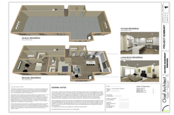
Pictorial Drawing Examplesof pictorial drawing use: Architects Usepictorial drawing to show what a finishedbuilding will look like.3Pictorial Drawing
Pictorial Drawing4Pictorial Drawing
5Pictorial Drawing
6Pictorial Drawing
7Pictorial Drawing
8Pictorial Drawing
9Pictorial Drawing
10Pictorial Drawing
11Pictorial Drawing
Pictorial Drawing Examplesof pictorial drawing use: Ad agencies Use12pictorial drawing to display new products.Pictorial Drawing
13Pictorial Drawing
14Pictorial Drawing
15Pictorial Drawing
16Pictorial Drawing
17Pictorial Drawing
Pictorial Drawing Pictorialdrawing is often used in explodeddrawings on production and assemblydrawings. Refer to Figure 12-118Pictorial Drawing
19Pictorial Drawing
Pictorial Drawing Viewsare made to illustrate the operation ofmachines, and equipment. Pictorialsketches are used to help conveyideas that are hard to describe in words.20Pictorial Drawing
21Pictorial Drawing
Pictorial Drawing22Pictorial Drawing
23Pictorial Drawing
24Pictorial Drawing
Pictorial Drawing Pictorialdrawing can be Perspective Views Isometric Views Oblique Views25Pictorial Drawing
Pictorial Drawing Pictorialdrawing can be Perspective Views Showobject as it actually looks to the eye. Commonly used in architectural work. Have non-parallel lines (x, y, z)26Pictorial Drawing
27Pictorial Drawing
28Pictorial Drawing
Pictorial Drawing Pictorialdrawing can be Isometric Views Easierto draw than perspective views. Do not look as good as perspective views. Commonly used in engineering work. Have parallel lines (x, y, z)29Pictorial Drawing
30Pictorial Drawing
31Pictorial Drawing
32Pictorial Drawing
Pictorial Drawing Pictorialdrawing can be Oblique Views Easierto draw than perspective views. Show less distortion than isometric views. Have parallel lines (x, y, z) Think “Front view depth”.33Pictorial Drawing
Isometric DrawingPictorial Drawing34
Isometric Drawing Pictorialdrawings, in general, are made toshow how something looks.35Pictorial Drawing
Isometric Drawing Sincehidden lines are “not part of thepicture” they are normally left out and arenot drawn in isometric drawings.36Pictorial Drawing
Isometric Drawing Isometricdrawing is Similar to isometric sketching except that itis created using instruments.37Pictorial Drawing
Isometric Drawing Objectsare aligned with three isometric axesat 120o angles to each other. Refer to Figure 12.4.38Pictorial Drawing
Isometric Axes39Pictorial Drawing
Isometric Axes40Pictorial Drawing
Figure 12-341Pictorial Drawing
Isometric Drawing X,Y and Z axes Must remain at 120 degrees to each other.42Pictorial Drawing
Isometric Drawing VerticalOrientation - Regular Position First position – theaxes meet at the upper front corner of theobject Secondposition – theaxes meet at the lower front corner of theobject.43Pictorial Drawing
Figure 12-444Pictorial Drawing
Figure 12-445Pictorial Drawing
Isometric Drawing HorizontalOrientation - Regular Position First position – theaxes meet at the left front corner of theobject Secondposition – theaxes meet at the right front corner of theobject.46Pictorial Drawing
Figure 12-447Pictorial Drawing
Figure 12-448Pictorial Drawing
Isometric Lines andNon-Isometric LinesPictorial Drawing49
Isometric Lines Anyline parallel to one of the isometric axesis called an isometric line.50Pictorial Drawing
Non-isometric LinesPictorial Drawing51
Non-isometric Lines Linesthat are not parallel to one of the axesare called non-isometric lines.52Pictorial Drawing
Non-isometric Lines Measurementslines.can be made only on isometric Non-isometriclines do not show in their truelength so they cannot be measured.53Pictorial Drawing
Non-isometric Lines54Pictorial Drawing
Non-isometric Lines55Pictorial Drawing
Drawing Non-Isometric Lines Todraw non-isometric lines: Locate the end points first. Use the Box Method. Refer to Figure 12-6.56Pictorial Drawing
Drawing Non-Isometric Lines57Pictorial Drawing
Drawing Angles Followthe procedure shown in Figure 12-7 Construct angle parts AO, AB, OB Transfer AO and AB to the isometric cube Lay off AO on the base of the cube Draw AB parallel to the vertical axis Finally, connect points O and B tocomplete the isometric angle58Pictorial Drawing
Drawing Angles59Pictorial Drawing
Isometric CirclesPictorial Drawing60
Isometric Circles Inisometric drawings, circles appear asellipses.61Pictorial Drawing
Drawing Isometric Circles Usethe four centered approximation methodto draw the ellipse. Refer to Figure 12-9.62Pictorial Drawing
Drawing Isometric Circles First,draw an isometric square, with thesides equal to the diameter of the circle63Pictorial Drawing
Drawing Isometric Circles Usea 30o 60o triangle to locate points A, B, C,D and points 1, 2, 3, 464Pictorial Drawing
Drawing Isometric Circles UseA and B as centers, and radius A2,draw the arcs65Pictorial Drawing
Drawing Isometric Circles UseC and C as centers, radius C4, drawarcs to complete the ellipse66Pictorial Drawing
Isometric Cylinder Todraw an isometric cylinder Use Figure 12-9 to construct the topellipse. Drop centers at a distance equal to theheight of the cylinder. Draw three arcs using the same radii asthe ellipse at the top. Noticethat the radii for the arcs at the bottommatch those at the top.67Pictorial Drawing
Isometric Cylinder68Pictorial Drawing
Isometric Quarter Rounds Todraw quarter rounds Refer to Figure 12-12. Follow procedure for quarters of circles. In each case measure the radii along thetangent lines from the corner. Then draw the perpendiculars to locate thecenters for the isometric arcs. Figure 12-13 shows how to draw outside andinside corner arcs.69Pictorial Drawing
Isometric Quarter Rounds70Pictorial Drawing
Isometric TemplatesPictorial Drawing71
Isometric Templates Isometrictemplates come in a variety offorms 15o, 30o, 45o, 50o, 60o They are convenient and can save youtime.72Pictorial Drawing
73Pictorial Drawing
Creating an Isometric DrawingPictorial Drawing74
Creating an Isometric Drawing MeasureTrue Length Lines fromOrthographic Projection drawings. Transfer Front View Xand Y TopView Xand Z Right Y75Sideand ZPictorial Drawing
Creating an Isometric Drawing FillerBlock Example Refer to Figure 12-17.76Pictorial Drawing
Creating an Isometric Drawing FillerBlock Example Draw the isometric axes in the firstposition.77Pictorial Drawing
Creating an Isometric Drawing FillerBlock Example Measure off the width, the depth and theheight of the block on the three axes.78Pictorial Drawing
Creating an Isometric Drawing FillerBlock Example Draw lines parallel to axes to make theisometric drawing of the block.79Pictorial Drawing
Creating an Isometric Drawing Filler80Block ExamplePictorial Drawing
Reversed Axes Todraw an object as if viewed from below,reverse the position of the axes. Follow example in Figure 12-20.81Pictorial Drawing
Reversed Axes82Pictorial Drawing
Creating an Isometric Drawing Whenlong pieces are drawn in isometric,make the long axis horizontal. Refer to Figure 12-2183Pictorial Drawing
Dimensioning Isometric DrawingsPictorial Drawing84
Dimensioning Isometrics Isometricsare seldom used as WorkingDrawings. Working Drawings are the drawings usedto actually construct the object.drawings are seldom dimensioned If dimensions are required, follow the newerunidirectional format. Refer to Figure 12-22. Isometric85Pictorial Drawing
Dimensioning Isometrics86Pictorial Drawing
Dimensioning Isometrics-Manually87Pictorial Drawing
Isometrics – Multiple ScalesPictorial Drawing88
Isometrics-Multiple Scales Isometric Onlyone scale is used Dimetric Twoscales are used. Trimetric Three89scales are used.Pictorial Drawing
Isometrics-Multiple Scales90Pictorial Drawing
Oblique DrawingsPictorial Drawing91
Oblique Drawings Obliquedrawings are Similar to isometric drawings, Are drawn on three axes (X, Y, Z). Two axes are parallel to the picture plane(the plane on which the view is drawn). These two axes always are at right angles. Think “Front View with depth”.92Pictorial Drawing
Oblique Drawings Inisometric drawings, only one axis is parallelto the picture plane. Refer to Figure 12-28.93Pictorial Drawing
Oblique Drawings Obliquedrawings show an object as if viewedface on. The object is seen squarely with nodistortion.94Pictorial Drawing
Oblique Drawing Rules Tocreate an oblique drawing: Draw a front view, long side horizontal Draw the depth Refer to Figure 12-29.95Pictorial Drawing
Oblique Drawing Rules96Pictorial Drawing
Oblique Projection Oblique Depthprojection is a way of showing depth.is shown by projector lines. Projectorlines represent receding edges of anobject. These lines are drawn at an angle otherthan 90o from the picture plane so they willbe visible in the front view.97Pictorial Drawing
Oblique Projection Lineson these receding planes that areparallel to each other are drawn parallel. Refer to Figure 12-30.98Pictorial Drawing
Oblique Projection Becauseoblique drawing can show one faceof an object without distortion it has a distinctadvantage over isometric. Obliquedrawings are useful for showingobjects with irregular outlines.99Pictorial Drawing
Oblique Drawing Types CavalierOblique receding lines are drawn full length. NormalOblique. receding lines are drawn 3/4 length. CabinetOblique. receding lines are drawn 1/2 length named this way because it is often used inthe furniture industry Refer to Figure 12-32100Pictorial Drawing
Oblique Drawing Types101Pictorial Drawing
Oblique Constructions Anglesand Inclined Surfaces Angles that are parallel to the picture planeare shown full size. For all other angles, lay the angle off bylocating both ends of the slanting line. Remember to lay off angles bymeasurements parallel to one of the axes.102Pictorial Drawing
Oblique Constructions ObliqueCircles Use the four-center method for ellipses. Ellipse templates give better results. If you use a template, block the obliquecircle as an oblique square.103Pictorial Drawing
Perspective DrawingsPictorial Drawing104
Perspective Drawings Aperspective drawing Is a three-dimensional representation of anobject as it looks to the eye from aparticular point. look the most like photographs of allpictorial drawings. lines on the receding planes that areactually parallel are not drawn parallel. These lines are drawn as if they wereconverging.105Pictorial Drawing
Perspective Drawings Aperspective drawing Is a three-dimensional representation of anobject as it looks to the eye from aparticular point.106Pictorial Drawing
Perspective Drawings Aperspective drawing look the most like photographs of allpictorial drawings.107Pictorial Drawing
Perspective Drawings Ina perspective drawing lines on the receding planes that areactually parallel are not drawn parallel. These lines are drawn as if they wereconverging.108Pictorial Drawing
109Pictorial Drawing
Perspective Drawings Perspectivedrawing is the most realisticlooking of the Pictorial drawing family. Twotypes of perspective drawings: One point. Two point. Often110used in architecturePictorial Drawing
Perspective Drawing Definitions Referto Figure 12-40 Sight lines which lead from the points onthe card and converge at the eye arecalled visual rays. The picture plane is the plane on which thecard is drawn. The station plane is the point from whichthe observer is looking at the card. A horizontal plane passes through theobserver’s eye. Where it meets the pictureplane, it forms the horizon line.111Pictorial Drawing
Perspective Drawing Definitions Wherethe ground plane on which theobserver stands meets the picture plane, itforms the ground line. The center of vision is the point at whichthe line of sight pierces the picture plane. The line of sight is the visual ray from theeye perpendicular to the picture plane. The point at which the receding axes meet(the projectors) is called the vanishingpoint.112Pictorial Drawing
Perspective Drawing Definitions113Pictorial Drawing
Perspective Drawing Definitions Ifthe object is seen from above, the view isaerial or bird’s eye view If the object is seen from below, the view isground or worm’s eye view If the object is seen so that the line of sightis directly on it, the view is a normal view114Pictorial Drawing
115Pictorial Drawing
116Pictorial Drawing
117Pictorial Drawing
118Pictorial Drawing
119Pictorial Drawing
Factors That Affect Appearance Inperspective drawing, the size of the objectseems to change as you move toward oraway from it. Refer to Figure 12-42 for explanation Each time the distance from the object isdoubled, the object appears only half aslarge120Pictorial Drawing
Factors That Affect Appearance Theshape of the object seems to changewhen viewed from a different position Looking at a square directly, the edges areparallel. Looking at it from an angle, the edgesseem to converge121Pictorial Drawing
One Point Perspective One-pointperspective, has one vanishing point also called parallel perspective. Twopoint perspective drawings have twovanishing points. Also called angular perspective122Pictorial Drawing
123Pictorial Drawing
124Pictorial Drawing
125Pictorial Drawing
126Pictorial Drawing
Placing ViewsChapter 5 - Page 140Pictorial Drawing127
Placing Views The“working space” of a drawing is the areainside the border. Objectsborder.are never drawn directly touching the Objectsare drawn so there is a spacebetween the object and the border line. Refer to Figure 5-28.128Pictorial Drawing
Figure 5-28129Pictorial Drawing
Figure 5-29130Pictorial Drawing
Placing Views 1.131Add the width and the depth of the object.Pictorial Drawing
Placing Views 1.Add the width and the depth of the object. For the Base, Fig 5-63, p152, The width is: 7.50” The height is: 2.25” 1.62” The depth is: 3.25” Width132 depth 7.50 3.25 10.75Pictorial Drawing
Placing Views 2.Measure the available drawing space insidethe border using the same scale that will beused to draw the object.133Pictorial Drawing
Placing Views 3.Subtract the total width of the objects fromthe width of the drawing space. For the BASE Width depth 7.50 3.25 10.75 Available 14.0 Dividedrawing space width 14.0– 10.75 3.25the remaining available space by 4. 3.25/ 4 0.8125 This is the amount of space that should be leftfor a border around the views.134Pictorial Drawing
Figure 5-30135Pictorial Drawing
Placing Views 3.Add the height and the depth of theobject. 4.Subtract this total from the height of thedrawing space. For the BASE Height depth 3.87 3.25 7.12 Available 8.0drawing space height 8.0– 7.125 0.875 Dividethe remaining available space by 4. 0.875/ 4 0.21875 This is the amount of space that should be leftfor a border around the views.136Pictorial Drawing
Figure 5-30137Pictorial Drawing
Locating and TransferringMeasurementsPictorial Drawing138
Locating Measurements Measurementsmade on one view can betransferred to another. This process also insures accuracy. Refer to Figure 5-33.139Pictorial Drawing
Locating Measurements140Pictorial Drawing
Locating Measurements 1.Draw upward from the Front view to locatewidth measurements in the Top view. 2.Draw downward from the Top View tolocate width measurements on the FrontView.141Pictorial Drawing
Locating Measurements142Pictorial Drawing
Locating Measurements 2.Draw across to the Side view from theFront view to locate height measurements Use a similar method to project heightmeasurements from the side view to thefront view143Pictorial Drawing
Locating Measurements144Pictorial Drawing
Locating Measurements Heightview.of Front view - transfer to Right-side Depthmeasurements show as verticaldistances in the Top view and as horizontaldistances in the the Right-side view.145Pictorial Drawing
Locating Measurements146Pictorial Drawing
Locating Measurements 3.Depth measurements show as Vertical distances - Top view Horizontal distances - Right-side view To transfer these measurements use Arcs 45o triangle Dividers Scale147Pictorial Drawing
Locating Measurements148Pictorial Drawing
Using Arcs to Transfer149Pictorial Drawing
Using Scale to Transfer150Pictorial Drawing
Using 45 Line to Transfer151Pictorial Drawing
Summary of Steps Followa step-by-step method to insureaccuracy Carry all views along together Do not attempt to finish one view beforestarting the others Use a hard lead pencil (4H or 6H) and light,thin lines for preliminary (layout) lines Use F, HB or H for final lines152Pictorial Drawing
Summary of Steps1.2.3.4.Consider the Characteristic View first.Determine the number of views.Locate the views.Block in the views with light, thin layoutlines.5. Lay off the principal measurements.153Pictorial Drawing
Summary of Steps6. Draw the principal lines.7. Lay off the measurements for details such ascenters for arcs, circles and ribs.8. Draw the circles and arcs.9. Draw any additional lines needed to completeviews.154Pictorial Drawing
Summary of Steps10. Darken the lines where necessary to makethem sharp and black and of proper thickness155Pictorial Drawing
156Pictorial Drawing
157Pictorial Drawing
158Pictorial Drawing
159Pictorial Drawing
160Pictorial Drawing
111 Pictorial Drawing Perspective Drawing Definitions Refer to Figure 12-40 Sight lines which lead from the points on the card and converge at the eye are called visual rays. The picture plane is the plane on which the card is drawn. The station plane is