Transcription
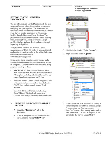
Chapter 1SurveyingPart 650Engineering Field HandbookFlorida SupplementSECTION C3: CIVIL 3D DESIGNPROCEDURESThe use of AutoCAD Civil 3D can provide the usergreater efficiency when downloading, processing,designing and plotting data. The procedures asdescribed below can be used when creating a Surfacefrom Survey points, creation of an Alignment,Profile, Sample Lines, and Cross Sections. Theprocedures also describe the use of Surface Editingtools, Grading tools, Design Corridors, Designprofiles, Surface Volume Tools and exporting andimporting design files.This procedure assumes the user has a basicunderstanding of Civil 3D tools. If a more detailedexplanation is required, refer to the online ReferenceGuides (RGuides) located atwww.nrcsknowledge.comC. Highlight the header “Point Groups”.D. Right-click and select “Update”.Before using these procedures, user should makesure the following programs and files are up to dateon computer. Compatibility issues may arise if anyprogram is not up to date: NRCS Civil 3D files – several features havebeen localized from National Headquarters Civil3D template including all of the Florida Surveycodes, Coordinate systems, and Styles Windows Mobile Device Center Program – usedto link external devices such as Data Collector(TSC3) data collectors and various TotalStations. Geoid Model files (GGF) installed usingAutoCAD and Trimble Link menu fromCivil3D. (An IT specialist may have to do this)I.CREATING A SURFACE USING POINTGROUPSA. Select the “Prospector” tab in theToolspace.B. If the “Toolspace” on the interface is notshow, open by typing “SHOWTS”E. Point Groups are now populated. Creating asurface requires the addition of point groups.A point group is a filtering processAutoCAD uses to filter survey codes such asNG, and or BM. The NRCS template is setup to filter the Survey Codes ONLY.(210-vi-EFH-Florida Supplement April 2016)FL1C3 - 1
Chapter 1SurveyingPart 650Engineering Field HandbookFlorida SupplementD. Give the surface a name by clicking insidethe values box where it says “Ognd”.Rename it and then click “OK”.II.CREATING A SURFACEA. With the survey imported and point groupsupdated. Go to the “Prospector” tab.B. If the “Toolspace” on the interface is notshown, open by selecting it from the menu(“General” “Toolspace”) or by typing in“SHOWTS”E. Next open the surface header. Select theexpansion icon (small plus sign) next to“Surfaces”. The new created surface willappear under the “Surfaces” header as thename that it was given.C. Right click “Surfaces” and select “CreateSurface ” from the list. A USDA/NRCStemplate may have a surface ready for use.FL1C3 - 2(210-vi-EFH-Florida Supplement April 2016)
Chapter 1SurveyingF. Open the named surface by clicking thecorresponding expansion icon.Part 650Engineering Field HandbookFlorida SupplementJ.Once a point group is added, the surface willbegin to take shape as contours and trianglesare added.G. Open the “Definition” by clicking thecorresponding expansion icon.H. Right-click “Point Groups” and select“Add”.K. Add the point groups to be included into thesurface until surface is complete.L. If no surface is visible after adding alldesired point groups.M. Right click on the name of your surface andselect “Surface Properties ”I.In the “Point Group” list select the pointgroups that will be contoured. Hit “Apply”and “OK”. Some point groups such as EXTree, or EX Bldg. will not be contoured sodo not add them to the surface. Add thepoint groups that are necessary based on thesurvey.(210-vi-EFH-Florida Supplement April 2016)FL1C3 - 3
Chapter 1SurveyingPart 650Engineering Field HandbookFlorida SupplementN. In the surface properties dialog box, under“Definition” expand the “Build” field withthe corresponding expansion icon.B. Right click “Figures” and select “CreateFigure Interactively ”C. Enter the name of the Figure (Road, Dit,Stream, etc )O. If “Use maximum triangle length” is set to“Yes”, either change it to“No” or adjust the “Maximum trianglelength” to the desired length. Onceadjustments are completed hit“Apply” ”OK”. This option is useful forexcluding points from the surface.III. MANUALLY ADDING A FIGURE TOTHE SURVEY DATABASEA. Open up a Survey Database by right clickingand selecting open for editD. Select the point objects in which the figurebelongs to.E. Once the figure point objects have beenselected, hit right-click and “Enter”.F. The “Figure Properties” dialog box willopen.FL1C3 - 4(210-vi-EFH-Florida Supplement April 2016)
Chapter 1SurveyingPart 650Engineering Field HandbookFlorida SupplementJ. Click “Apply” and “OK”.K. Go back to the “Figures” and find the figurethat was just created. Highlight and rightclick select “Insert into drawing”.G. If the line is either a Breakline or Lot Lineclick “yes”L. The figure will now be inserted into thedrawing.IV. APPLYING FIGURES AS BREAKLINESA. Go to the “Survey” tab of “Toolspace”.H. Select a layer,B. Under “Survey Databases”, double –clickon the survey you wish to create breaklinesfrom to expand it.C. Right-click on “Figures” and select “CreateBreaklines”I.Select “Bylayer” for a style.(210-vi-EFH-Florida Supplement April 2016)FL1C3 - 5
Chapter 1SurveyingPart 650Engineering Field HandbookFlorida Supplement6. Give the breakline a “Description”7. Under “Type” select “Standard”8. Click “OK”.D. The “Create Breaklines” dialog box willopen.H. AutoCAD will create breaklines from thespecified figures in that surface.V. MANUALLY ADDING BREAKLINES TOA SURFACEA. Invoke the polyline command (PL) and theninvoke the point object command (‘po).B. Click on points using the codes as the guide“EMB1 to EMB1” for exampleC. Once all of the lines that represent a surfacefeature, such as an embankment line or acenterline of a ditch, have been drawn breaklines can be created.Note: The point object command must be invokedwithin another command. When invoked, selectpoints in the drawing for the command to work.When two points are chosen a polyline will be drawnbetween the points.E. Select the Surface from which to create thebreaklines.F. Toggle on or off the lines you wish to createbreaklines from. Click “OK”G. The “Add Breaklines” dialog box willappear.FL1C3 - 6D. Go to the “Prospector” tab.1. Go to “Surfaces”.2. Open the desired surface’s tree byselecting the expansion icon next to thesurface name.(210-vi-EFH-Florida Supplement April 2016)
Chapter 1SurveyingPart 650Engineering Field HandbookFlorida Supplement3. Open the “Definition” by selecting thecorresponding expansion icon.4. Right-click on “Breaklines”. Select“Add” from the list.E. The “Add Breaklines” dialog box willopen.5. Give the breakline a name (ex. ProjectName)G. Once the breakline is added, the surface willautomatically update. Continue addingbreaklines until surface is defined.H. Save the file once the surfaces have beendefined.6. Set “Type” to “Proximity”.VI. SWAPPING EDGES OF A SURFACE7. Click “OK”.A. Click on the surfaceB. The surface ribbon will populate at the topof the drawingC. Click on the Edit Surface icon in the Modifysection of the ribbonD. Select Swap Edge from the dropdown menuF. Select all Polylines designated as abreakline.(210-vi-EFH-Florida Supplement April 2016)FL1C3 - 7
Chapter 1SurveyingPart 650Engineering Field HandbookFlorida SupplementG. Click on the edge. The edge will changedirection and locationE. The cursor will turn into a rectangle andprompt you to select an edge to swapF. Find an edge that is to be swappedH. Press escape to exit the modifier and allowthe surface to repopulateNote: if a notification appears saying that theselected edge cannot be swapped choose a differentedge to swap. If enough edges are swapped then theoriginal edge that was targeted to be swapped canbe swapped.FL1C3 - 8(210-vi-EFH-Florida Supplement April 2016)
Chapter 1SurveyingPart 650Engineering Field HandbookFlorida SupplementVII. CREATING AN ALIGNMENT FROM APOLYLINEA. To create an alignment with a polyline,select “Polyline” and draw a polyline on asurface. Or, enter the command “pline” todraw the polyline.E. Once the polyline is selected a prompt willask to accept the alignment direction orreverse it. Press enter to accept the directionor click Reverse.B. Once drawn, a polyline can be used for analignment.C. Go to the “Alignments” menu, left click“Create Alignment by Polyline”.F. Once the direction of the alignment isspecified, a dialog box to create thealignment will open.D. Select the polyline to be converted to analignment.(210-vi-EFH-Florida Supplement April 2016)FL1C3 - 9
Chapter 1SurveyingPart 650Engineering Field HandbookFlorida Supplementdistance per tangent and apply a curve atevery intersection of the tangents).8. Toggle on “Erase existing entities” toerase the existing polyline from thedrawing if it is not already toggled on.B. Click “OK”, the polyline will convert to analignment.1. For “Site” select “None”2. Give the alignment a name (ex. Ditch 1)3. Give a small description if desired.4. Specify the starting station of youralignment (0 00.00 or 10 00.00).VIII.Create an Alignment from Layout TOOLSA. Go to the “Alignment” menu, scroll to“Create Alignment by Layout”, and leftclick to select.5. Specify the alignment style, these stylesare in the template and one may bechosen as a style (Final for plotting,Layout and Design, No label display,Standard, and None).6. AutoCAD will automatically create alayer based on the name of thealignment. Or one can be chosen by theicon beside the “Alignment layer”.7. Toggle off “Add curves betweentangents” (If this is toggled on, thealignment style will specify the radiusFL1C3 - 10B. The “Create Alignment – Layout” dialogbox will appear.(210-vi-EFH-Florida Supplement April 2016)
Chapter 1Surveying1. Give the alignment a name.2. Give the alignment a small description ifdesired.3. Specify the starting point of youralignment 0 00.00 or 10 00.00. Thisexample doesn’t have any.4. For “Site” select “None”.5. Specify an “Alignment Style”. Thesestyles are in the template and one maybe chosen as a style (Final for plotting,Layout and Design, No label display,Standard, and None).Part 650Engineering Field HandbookFlorida Supplement6. Specify an “Alignment Label Style”.These styles are within the AutoCADTemplate (Major(Parallel) MinorGeometry 100 and 50,Major(perpendicular) Minor Geometry100 and 50, standard, and None)B. Click “OK”.C. The “Alignment Layout Tools” tool barwill appear. Here you can draw thealignment based on the structure of thealignment. Each tool has a purpose based onthe type of alignment that needs to be drawn.See Figure G-7.Figure G-7: Alignment Layout ToolsD. Use the first icon if you wish to draw line toline for the alignment. Press “Enter” to endthe command.For a more detailed explanation of thealignment tools please refer to theNRCSknowledge website or the referencemanual.(210-vi-EFH-Florida Supplement April 2016)FL1C3 - 11
Chapter 1SurveyingPart 650Engineering Field HandbookFlorida SupplementIX. CREATING PROFILES FROM ANALIGNMENTA. Profiles from an alignment can be created inseveral ways. The most basic is using asurface and an alignment.B. Go to “Profiles”, scroll to “Create Profilefrom Surface”.H. The “Create Profile View” dialog box willappear.C. The “Create Profile from Surface” dialogbox will appear.I.Select the desired alignment.J.Give the profile a name.K. Give the profile a description if desired.D. If there are multiple alignments, use thedropdown menu for a selection of thealignments. Choose an alignment the stationrange and the data will come up.E. If you have more than one surface (TIN, orDTM) select it on the right hand window.F. Select the “Add” button on the right handside of the screen to add to the Profile List.G. Click “Draw in Profile View”.FL1C3 - 12L. Set the “Profile view style” to “A 20Hx10V(VP Scale 20)” (this represents the verticalexaggeration. 2:1 for every 1 foot horizontal,there’s 2 feet vertical).M. Toggle off data bands. (Data bands mayhave their own dialog box following thoseexplained below in newer versions ofAutoCAD)N. Click “Next”.O. The next dialog box allows a specific stationrange in which can be set instead of thewhole alignment. AutoCAD defaults to thebeginning and to the end of the alignment.Click “Next” to accept the whole alignment.(210-vi-EFH-Florida Supplement April 2016)
Chapter 1SurveyingPart 650Engineering Field HandbookFlorida SupplementB. In the Create Assembly dialog box give theassembly a name and click “OK”P. The next dialog box allows specify theelevation range. AutoCAD defaults to themaximum and minimum elevation that thesurface allows. Click “Next”.Q. The next dialog box is for more displayoptions if there’s a need to edit the profiledisplay options. Select “Create ProfileView”.R. Move away from the surface to place theprofile. Once the profile is placed, aviewport (VP) can be created and set to adistance of 1” 20’ as per the style that wasused.X. CREATING AN ASSEMBLY FOR ACORRIDORC. Pick a spot in the drawing where theassembly will be placed1. A line with a blue circle will appearIn this example a V-ditch with side slopes of 3:1 willbe createdA. Click on the Corridors menu and selectcreate AssemblyD. Open the Tool Palette if it is not alreadyopenedE. Click on the Generic tab(210-vi-EFH-Florida Supplement April 2016)FL1C3 - 13
Chapter 1SurveyingPart 650Engineering Field HandbookFlorida Supplement1. Switch to the Parameters tab and changethe slope to 33%1. Click on LinkSlopeToSurface2. Select the blue circle in the assembly2. Click Apply and OK3. Press enterH. Click on the AssemblyF. Click on the subassemblyI.G. On the Assembly ribbon select theSubassembly properties iconFL1C3 - 14On the Assembly ribbon select the mirroricon1. Click on the assembly and press enter,then click on the vertical green assemblyline(210-vi-EFH-Florida Supplement April 2016)
Chapter 1SurveyingPart 650Engineering Field HandbookFlorida SupplementD. Select the profile to be labeledE. Pick the end points of the Polyline targetendpoints1. The endpoints will need to be selectedtwice: once for the station and the otherfor the elevationXI. CREATING A DESIGN PROFILEA Design Profile is projecting a desired bottomor top of something in relation to the existingground. It is for construction purposes and fromit a corridor can be created.A survey, surface created, horizontal alignment,and a profile created to represent the existingsurface along the horizontal alignment areneeded.A. Go to the created profile for the alignmentF. The label for the Station and Elevation willcome up. if an AutoCAD messageindicating a subscription CUIX file that wasunable to open appears click “OK”B. Invoke the polyline command and draw apolyline to represent a new design profileA polyline will just mark out the stationing andelevations on a profile to be later designed.C. From the “Profiles” menu select- “AddProfile View Labels” and then “StationElevation”G. Go to the Profile Menu1. Select Create Profile by Layout2. Select the Profile3. The alignment will be selectedautomatically if it is just a single(210-vi-EFH-Florida Supplement April 2016)FL1C3 - 15
Chapter 1Surveyingalignment. (If multiple alignmentschoose the one to create a profile from).H. The Create Profile- Draw New menu willappearPart 650Engineering Field HandbookFlorida SupplementXII. CREATING A CORRIDOR USING ANALIGNMNET, DESIGN PROFILE, ANDASSEMBLYA. On the Home ribbon click on the corridoriconB. The Create corridor window will appear1. Give the corridor a name2. Set the corridor style to corridor3. Choose the Alignment4. Choose the Design profile (Do notchoose OGND)5. Choose the Assembly1. Give the new profile a name6. Choose the Target Surface2. Select Profile Style “Fini”7. Click OK3. Select Profile Label Set “Finished”4. Click “OK”I.The “Profile Layout Tools” toolbar willappear1. Select the first button:Draw TangentsJ.Select the endpoints of the Polyline until theend of the Profile1. The design profile will appear in blueFL1C3 - 16(210-vi-EFH-Florida Supplement April 2016)
Chapter 1SurveyingC. The Baseline and Region Parameterswindow for the chosen alignment willappearPart 650Engineering Field HandbookFlorida SupplementD. Click on the “Create new Surface” icon inthe upper left hand corner1. Click Apply and then OKE. The new surface will appearXIII. CREATING A DETACHED SURFACEFROM THE CORRIDORA. Left-click on the corridor to bring up thecorridor ribbonB. Click on the Corridor Properties icon in theModify Corridor panelF. Under the Specify code heading make surethe dropdown menu reads Top. Click on theplus icon next to the dropdown menuG. Click on the dropdown menu and selectDatum. Click on the plus icon next to thedropdown menuC. Click on the Surfaces tab in the CorridorProperties dialog box to bring up the surfaceinformationH. Click on the dropdown menu and select“Daylight Fill”. Click on the ( ) plus iconnext to the dropdown menu(210-vi-EFH-Florida Supplement April 2016)FL1C3 - 17
Chapter 1SurveyingI.Click on the dropdown menu and selectDaylight Cut. Click on the plus icon next tothe dropdown menuJ.The codes should be inserted under theSurface name. Click Apply and OKPart 650Engineering Field HandbookFlorida SupplementB. Next, select an alignment using the selectionbox, this alignment should be the alignmentto cut cross sections from.XIV. CREATING SAMPLE LINESOnce an alignment and profile(s) are created,cross sections can be created along thealignment. The first step is producing samplelines by AutoCAD. A sample line is a previewof where the cross sections will appear along thealignment. Sample lines display the right and leftswath (cross section width) and lines will appearalong the alignment at intervals set by the user.Any adjustments to the width of the crosssections or the intervals can be completed beforecutting the cross sections.C. The “Create Sample Line Group” dialogbox will appear.A. Go to the “Sections” menu, select “CreateSample Lines”. This will produce thegraphic preview of where the cross sectionswill be cut and produced.D. Enter a name for the sample lines.E. Give a short description if desired.F. For the “Sample line style” select “Line”.G. For the “Sample line label style” select“Station at One End of Sample Line”.FL1C3 - 18(210-vi-EFH-Florida Supplement April 2016)
Chapter 1SurveyingThis will produce a station location next tothe sample line.H. Verify the alignment name in “Alignment”.I.Click “OK”.J.Use the “Sample Line Tools” toolbar to setup the sample lines.Part 650Engineering Field HandbookFlorida SupplementM. Select “Sample Line Creation Method”tool icon to pick the type of sample lines toproduce, such as one sample line versusmultiple sample lines along the alignment.N. To create multiple cross sections along thealignment select “By range of stations”.O. The “Create Sample Lines - By StationRange” dialog box will appear.K. If only one cross section is needed, move thecursor along the alignment and select adesired area. See Figure I-5.1.“Enter the Left swath width 30.000’ ”look for this at the command line.2. “Enter the Right swath width 30.000’ ”.L. Once this is entered, a sample line will bedisplayed along the alignment. To create across section from this, proceed with CreateCross Sections in AutoCAD Civil 3D.P. The first header “General” lists thealignment where the sample lines will beproduced.Q. The header “Station Range” can be set forthe whole alignment or can be set to asection of the alignment by selecting“False” on either ends of the alignment orboth ends of the alignment. In this case thewhole alignment will be used.(210-vi-EFH-Florida Supplement April 2016)FL1C3 - 19
Chapter 1Surveying1. “From alignment Start” select “True”2. “To alignment End” select “True”Part 650Engineering Field HandbookFlorida SupplementW. If zoomed in on the ends of the sample line thestation label will be displayed.R. In the headers “Left Swath Width” and“Right Swath Width”. Keep the “Snap toAlignment” to “False” to have moreoptions to select a width. Each width is set to30’ from the alignment. But can be set to adesired width per side of the alignment.S.In the header “Sampling Increments”select “True” in “Use SamplingIncrements”. Set “Increments AlongTangents, Curves, and Spirals” to desiredincrements. This will place a sample linealong the alignment. Since the alignment hasno curves or spirals, this will have no effect.T. In the header “Additional SampleControls”1. “At Range Start” select “True”2. “At Range End” select “True”XV. CREATING CROSS SECTIONS FROMSAMPLES LINESA. With sample lines created, cross sections canbe produced (if there was no editing duringthe placement of the sample lines). Go to the“Sections” menu, select “Create MultipleSections Views”.3. “At Horizontal Geometry Points”select “False”. This will omit placing across section at every turn in thealignment.4. “At Super elevation Critical Stations”select “False”U. Click “OK”.V. The sample lines will be produced along thealignment selected.B. The “Create Multiple Section Views”dialog box will appear.FL1C3 - 20(210-vi-EFH-Florida Supplement April 2016)
Chapter 1SurveyingC. Enter a name in the “Section View Name”field (ex. Section 1).D. Enter a small description if desired.Part 650Engineering Field HandbookFlorida SupplementM. The next dialog box allows specify theelevation range. AutoCAD defaults to themaximum and minimum elevation that thesurface allows. Click “Next”.E. Select a “Section View Style” – Within thetemplate there are several styles to choosefrom (ex. “A 20Hx10V (VP Scale 20)”).F. Select “Alignment” (if there are multiplealignments). It will default to the currentalignment if only one is present.G. Select the “Sample line group name”(There may be more than one sample linegroup within the alignment.)H. Click NextI.Select a template for which the section viewwill be placed on sheets (20 Scale, 40 Scalefor example). The templates can be foundon the hard drive under the NRCS SectionSheets 2014 drawing file in the AutoCADTemplates folder.J.Select a “Group Plot Style” this orients theplacement of the cross sections. (10 Per Row 10 cross sections per row).N. The next dialog box shows the sections thatwill be drawn in the profile views. Thesurface should be seen. Click “Next”.K. Select NextO. Toggle off “Add Data Bands” on the nextdialog box. (Data bands may have their owndialog box following those explained belowin newer versions of AutoCAD)L. The next dialog box allows the user tospecify the offset range. AutoCAD defaultsto an automatic range. Click “Next’.1. Click “OK” or “Create Section Views”and place the cross sections away fromthe surface and profile.(210-vi-EFH-Florida Supplement April 2016)FL1C3 - 21
Chapter 1SurveyingPart 650Engineering Field HandbookFlorida Supplement2. The section view of “A 20Hx10V (VPScale 20)” means a verticalexaggeration of 2:1 and a viewport scaleof 1” 20’.3. Save the fileXVI. PRODUCING MATERIALSA. Left click on one of the section views topopulate the section view options under thehome ribbonF. Under the Object Name heading select the Click here to set all value next toOriginal Ground1. Choose “Ognd” from the dropdownmenuB. Select the Compute Materials icon in theLaunch Pad portion of the ribbonC. The Select a Sample Line Group pop-upwindow will appearG. Under the Object Name heading select the Click here to set all value next to thecorridor surface name (in this case it isExample Example, see step 5b for why thisis the case)D. Click “OK”E. The Compute Materials pop-up window willappearNote: make sure that under the Quantity TakeoffCriteria heading in the upper left-hand corner EarthCut and Fill is selectedH. Click OKFL1C3 - 22(210-vi-EFH-Florida Supplement April 2016)
Chapter 1SurveyingPart 650Engineering Field HandbookFlorida SupplementD. The Change Volume Tables pop-up windowwill appearXVII. CREATING A VOLUME TABLE FROMSAMPLES LINESA. Left-click and then right-click on a section tobring up its optionsB. Select Section View Group PropertiesC. Under the Section Views of the Section ViewGroup Properties pop-up window select theicon under the Change Volume TablesheadingE. Under the Type heading make sure Materialis selected and under the Select table styleheading make sure Standard is selected1. Click “Add ”(i) The Select Materials pop-up windowwill appear. Make sure both “EarthCut” and “Earth Fill” are checkmarked2. Click “OK”F. Click “Apply” and then “OK”(210-vi-EFH-Florida Supplement April 2016)FL1C3 - 23
Chapter 1SurveyingPart 650Engineering Field HandbookFlorida SupplementXVIII. CREATING A FEATURE LINE FORGRADINGG. On the output ribbon select Create SectionSheets under the Plan Production portion ofthe ribbonA feature line is necessary to design an earthworkobject. For our example, we will be drawing a smallembankment. There are multiple methods forcreating a feature line. This procedure will detailinstructions to create feature line from scratch. It’simportant that the surface was properly created foruse with the Florida AutoCAD Civil DesignProcedures.A. Invoke the polyline command and draw apolylineH. On the Create Section Sheets pop-up windowselect the Alignment. Sample line groupname, and section view group you wish tocreate the section views forI. Under the Layout name heading give thesection sheets a nameJ. Click “Create Sheets”B. Click on “feature line” from the Homeribbon and select “Create Feature Line fromObjects”Note: Once you click create sheets Civil3d will ask tosave your work. Click “OK” to proceed and thesection sheets will be created and placed in thedrawingFL1C3 - 24(210-vi-EFH-Florida Supplement April 2016)
Chapter 1SurveyingPart 650Engineering Field HandbookFlorida Supplement3. Make sure the style is set to GeneralFeature Lines4. Make sure the Erase existing entities ischecked on5. Click “OK”Note: to assign elevations to the feature line eithercheck mark on the “Assign elevations” box in thecreate feature lines dialog box or click on theElevation Editor icon on the Feature Line ribbon.C. Select the polyline and press enterD. The Create Feature Lines dialog box willappearXIX. FEATURE LINE FROM LAYOUT TOOLSA. To create a feature line click on “FeatureLine” from the Home ribbon and then select“Create Feature Line”B. The “Create Features Line” dialog boxwill open.C. Select a site. Every feature line needs a siteon which to be built on and referenced to.D. Check the name box and create a name forthe feature line.E. Select a style for the feature line. The buttonto the right of the style drop-down boxprovides opportunity to edit the style.F. Select a layer for the feature line and click“OK”.1. Choose the site of the feature line2. Check the Name box and give thefeature line a name(210-vi-EFH-Florida Supplement April 2016)FL1C3 - 25
Chapter 1SurveyingC. Specify the location of the feature line’sinitial point. Then input the elevation of thepoint.D. Select the next points of the feature line andselect the elevations for each point. Featurelines can be easily modified using buttons onthe “Feature Line” toolbar. An elevation isnot necessary for each point. A line segmentcan be a specific grade/slope or the point canbe placed on the surface.Part 650Engineering Field HandbookFlorida SupplementE. The feature line has now been completed. Itwould be beneficial to explore the“Features Line” toolbar in order to explorethe functionality of it. Editing elevations,filleting, quick profiles, and splines are just afew of the abilities of the toolbar. Featurelines can also be created from polylines. Thenext step in determining the earthworkvolumes of a project is to create a gradingfrom the feature line to the surface.XX. CREATING A GRADING OBJECT FROMA FEATURE LINEGrading consists of defining a baseline with someelevation and criteria for defining the projection. Thecriteria used consist of a target: surface, elevation,relative elevation, distance, slope, or grade. Thefollowing procedure will create a 3:1 slope for theembankment feature line previously drawn.A. To create a grading click on “Grading onthe home menu and select “Gradingcreation tools”. The Grading CreationTools window will pop up.FL1C3 - 26(210-vi-EFH-Florida Supplement April 2016)
Chapter 1SurveyingPart 650Engineering Field HandbookFlorida SupplementB. In order to create a grading, a grading groupmust first be created. On the “GradingCreation Tools” toolbar, select the “Set theGrading Group” button located on the farleft of the toolbar. This will open the “Site”dialog box.C. Once in the “Site” dialog box, choose thesite for which the grading group will be apart of or click on the “Select from theDrawing” icon to choose a site within in thedrawing. Click “OK” once a site is chosenD. The Create Grading Group dialog box willappear1. Make sure to check automatic surfacecreation and select the surface style.2. Check the volume base surface box andselect the base surface of the grading.Usually this will be the main naturalground surface.3. Select “OK”.(210-vi-EFH-Florida Supplement April 2016)FL1C3 - 27
Chapter 1SurveyingPart 650Engineering Field HandbookFlorida Supplementbutton that reveals the drop-down. Select the“Create grading” button.E. The “Create Surface” dialog box will openand check that the conditions of the surfaceare satisfactory and click “OK”.F. Next step would be to confirm the targetsurface by selecting the “Set the TargetSurface” button. It’s the second button fromthe left on the “Grading Creation Tools”toolbar. Confirm the target surface in thedialog box and click “OK”.G. Within the “Grading Creation Tools”toolbar, a dropdown box is located. The boxcontains the grading criteria. Select theappropriate criteria. For this example,“Slope or Grade to Surface (Cut andFill)” will be selected since the grading willgo from the feature line to the base surface.I.Select the feature that is intended to begraded then select the side that grading willoccur. Since the example is an embankment,the side to be graded is outside of th
(210-vi-EFH-Florida Supplement April 2016) FL1C3 - 1 SECTION C3: CIVIL 3D DESIGN PROCEDURES The use of AutoCAD Civil 3D can provide the user greater efficiency when downloading, processing, designing and plotting data. The procedures as described below can be used when creatin