Transcription
The Physics GRE
Sample test put out by ETShttps://www.ets.org/s/gre/pdf/practice book physics.pdfOSU physics website has lots of tips, and 4 additional gs gre.phpSolutions to these tests are available online in some places (but not all explanations aregood) .Study guides and supporting material can be borrowed for use in the PRB .
The oscilloscope
A steady current or a slowly changing potentialcan be measured by a VoltmeterRV A steady current or a slowly changing current can be measured byan Ammeter-RV But the voltage may be oscillating at 10 Khz . that is 10,000oscillations per second.How should we measure voltages that change quickly ?-
There are two ways of using an oscilloscopeThe X direction is a uniform ratesweep, so it marks time tPut the voltage V to be measured onthe Y terminalsComparing two different voltage sources:Put first voltage on the X terminalsPut second voltage on Y terminals
ymaxxmin yxmin max
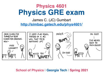
What is the ratio of the frequency of vertical oscillationsto the frequency of horizontal oscillations ?
Example of an analog oscilloscope Lissajous figure, showing a harmonic relationship of 1horizontal oscillation cycle to 3 vertical oscillation cycles.
The Capacitor
Current flows according to Ohm's lawRIV IRV -Wire has a break, so no current flowsRV -There is no conductor between the twoplates of a capacitorCRSo how does any current flow?V -
I -The battery pushes electronsout from its negative terminal.In effect this creates a flow ofpositive charge out of the positiveterminal----But after a very short time electronspile up near the end of the wire.They repel each other, pushingback against the pressure from thebattery
Can we do anything to make the current flow go on longer ?Suppose we expand the end of the wire so that it has a large area .Then we can flow out more charge before the 'pushback' stops the current flow ----------- --
Can we do even better ?If we could place some positive charges near the negative plate, that would attractthe electrons, and reduce the tendency of the electrons to push back .- But where would we get such charges from ?---- -------- --
The capacitorLarge area AStore a lotof charge ! - Small distance d-
Defining capacitanceQ- Q2QCCV - 2Q2V --Voltage is like a 'pressure'More Voltage allows storage of more chargeUnits:Q / VQ CV1 CoulombQC V1 Farad1 Volt
At the start capacitor plates acceptcharges with no pushbackCRRSo C can be replaced with a wireVI RV Q0Q0CR0QV0 CWith some charge, the capacitor actslike a 'reverse battery'So C can be replaced with a wire I -QQCVV0V RQV CThe charge on the capacitorapproaches Q C VRThen there is no net voltage in thecircuit, so I 0V RVRV-V -
If you quickly vary the voltage, then the capacitor never charges very muchThere is hardly any 'pushback voltage'CRRVVSo in this situation C can be replaced with a wire-
GR9677
GR9677V
GR9677
GR9677Q CV VU- CQ CV V- CQ CV U- CU
Energy stored in a capacitorStart wth no charge on plates; the energy is zeroThe battery moves charge from the negative plate to the positive plate0Suppose the charges on the plates have reached Q andQ0Then the potential difference is V CQ0Q0Q0Move an additional charge dQ00QThis needs an energy dE V dQ0 dQ0CThus the total stored energy isE Note thatZQQ0 02Q0QdQ0 C2CQ2112E CV QV2C22dQ0
Charging/discharging a capacitor
ChargingI(t) Q(t)Q(t)CRdQ(t) I(t)dtV -The capacitor acts like a 'reverse battery'Q(t)V (t) CI(t)RV --VSolutionV (t) I(t)RQ(t)V I(t)RC1 dQ(t)dI(t) RC dtdtdI(t) dt1I(t)RCI(t) I0 eVI0 RtRC
DischargingI(t) Q(t)RQ(t)CV (t) I(t)RQ(t) I(t)RC1 dQ(t)dI(t) RC dtdtdI(t)1 I(t)dtRCI(t)Q(t)V (t) CRSolutionI(t) I0 etRCV0Q0I0 RRCQ(T ) Q0 etRC
GR9277
GR9277
GR9277
GR9277
Inductors
An inductor is just a coilThere is no resistanceSo if a steady current is passing, there is no effect of the inductor . it is just apiece of ordinary wire with no resistanceBut if we try to change the current, the inductor does not want to allow that tohappen, and it resists the change .
When current passes through the coil, there is a magnetic field generated(a)(b)I 0I 0But a magnetic field costs energy, so we cannot immediately go from (a) to (b)What can stop the current from increasing? The coil develops a reversevoltage, which opposes the increase of current .
-dI 0dtHow much is this reverse voltage ?dIV /dtdIV LdtCurrent through an inductor cannot change quickly: the inductor will oppose thechangeIf we make a slow change in the current, the inductor has no effect: it can beignored
(D) 40 mF(E) 400 mF39. Which two of the following circuits are high-passfilters?(A)(B)(C)(D)(E)I and III and IIII and IVII and IIIII and IV(GRO177)
(C) 4 mF(D) 40 mF(E) 400 mF39. Which two of the following circuits are high-passfilters?n(A)(B)(C)(D)(E)I and III and IIII and IVII and IIIII and IV(GRO177)
GR9677
High frequencyLow frequencyGR9677
Charging/discharging an inductor
ChargingdI(t)V (t) LdtLRRVVI(t) -I(t) -The inductor acts like a 'reverse battery'VVV (t) I(t)RdI(t)L I(t)RdtdI(t)V dtLRI(t)LSolutionI(t) I0 (1VI0 ReRLt)
DischargingCurrent cannot suddenly stop, since the energy in the magnetic field cannot vanishsuddenly .So now the inductor has to act like a 'forward battery'LLRRI(t)I(t)V (t) I(t)RdI(t)L dtdI(t)dI(t)V (t) L()dt I(t)RRI(t)SolutionI(t) I0 eRLt
GR017740. In the circuit shown above, the switch S is closed at t 0.Which of the following best represents the voltage across theinductor, as seen on an oscilloscope?(A)(B)(C)(D)(E)
GR017740. In the circuit shown above, the switch S is closed at t 0.Which of the following best represents the voltage across theinductor, as seen on an oscilloscope?(A)(B)(C)(D)(E)
Oscillating currents
An oscillating current or voltage sourceI I0 cos(!t)V V0 cos(!t)I0Average current is zeroI01Squaring gives positive function, average is I 202Root mean square current (RMS current)Irms1 p I02
2VHeat dissipated I 2 R VIRNo heatdissipatedLRHeat dissipated2hI 2 iR IrmsRC
A series AC circuit with impedance Z consistsof resistor R, inductor L, 40.andAcapacitorseries ACC,circuit with impedance Z consistsas shown above. The ideal emf sourcehas R, inductor L, and capacitor C,of resistora sinusoidal output given byand the current is given bye as shownemax sinabove.wt , The ideal emf source hasI aI sinusoidalf ). given by e emax sin wt ,max sin( wt outputWhat is the average power dissipatedtheand theincurrentis given by II max sin( wtf ).What iscurrent.)the average power dissipated in thecircuit? ( I rms is the root-mean-square(A)(B)(C)(D)(E)2IrmsR1 2I R2 rms1 2Irms Z21 2I R cos f2 rms1 2I Z cos f2 rmscircuit? ( I rms is the root-mean-square current.)2R(A) Irms(B)1 2Irms R2(C)1 2I Z2 rms(D)1 2I R cos f2 rms(E)1 2Irms Z cos f2
A series AC circuit with impedance Z consistsof resistor R, inductor L, 40.andAcapacitorseries ACC,circuit with impedance Z consistsas shown above. The ideal emf sourcehas R, inductor L, and capacitor C,of resistora sinusoidal output given byand the current is given bye as shownemax sinabove.wt , The ideal emf source hasI aI sinusoidalf ). given by e emax sin wt ,max sin( wt outputWhat is the average power dissipatedtheand theincurrentis given by II max sin( wtf ).What iscurrent.)the average power dissipated in thecircuit? ( I rms is the root-mean-square(A)(B)(C)(D)(E)2IrmsR1 2I R2 rms1 2Irms Z21 2I R cos f2 rms1 2I Z cos f2 rmscircuit? ( I rms is the root-mean-square current.)2R(A) Irms(B)1 2Irms R2(C)1 2I Z2 rms(D)1 2I R cos f2 rms(E)1 2Irms Z cos f2
RLC circuits
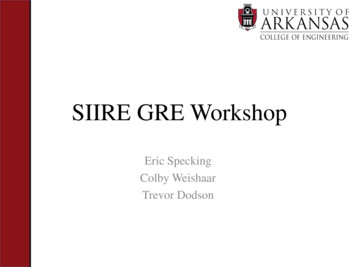
(GRO177)38. An AC circuit consists of the elements shownabove, with R 10,000 ohms, L 25 millihenries,and C an adjustable capacitance. The AC voltagegenerator supplies a signal with an amplitude of40 volts and angular frequency of 1,000 radiansper second. For what value of C is the amplitudeof the current maximized?(A) 4 nF(B) 40 nF(C) 4 mF(D) 40 mF(E) 400 mF
dIV LdtWe writeI Re [ I0 ei ! t ]and just write the complex current from now on.I I0 ei!tdI i!IdtV (iL!)ICompare toV IRReactanceiL!
QQCurrent I means that I coulombsflow into the plate each secondIdQ IdtQ CVV V0 ei!tdVC IdtC(i!V ) I1V I()iC!Compare toV IR1ReactanceiC!
iL!1iC!LCRV V0 ei!tRef f1 R iL!iC!VI Ref f
The current is maximal when the effective resistance is minimal . V I Ref f Ref f1 R i( L!)C!12 Ref f R ( L!)C!2If2R, C, L are fixed, and we can only vary ! , then Ref f is minimal when1! pLCAt this frequency we say that the circuit is in RESONANCE
GR9277
GR9277
(GRO177)38. An AC circuit consists of the elements shownabove, with R 10,000 ohms, L 25 millihenries,and C an adjustable capacitance. The AC voltagegenerator supplies a signal with an amplitude of40 volts and angular frequency of 1,000 radiansper second. For what value of C is the amplitudeof the current maximized?(A) 4 nF(B) 40 nF(C) 4 mF(D) 40 mF(E) 400 mF
(GRO177)38. An AC circuit consists of the elements shownabove, with R 10,000 ohms, L 25 millihenries,and C an adjustable capacitance. The AC voltagegenerator supplies a signal with an amplitude of40 volts and angular frequency of 1,000 radiansper second. For what value of C is the amplitudeof the current maximized?(A) 4 nF(B) 40 nF(C) 4 mF(D) 40 mF(E) 400 mF
Challenge question
GR8677
Sample test put out by ETS OSU physics website has lots of tips, and 4 additional tests Solutions to these tests are avai