Transcription
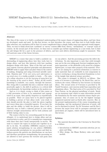
MSE307 Engineering Alloys 2014-15 L1: Introduction, Alloy Selection and LifingD. Dyeaa RmG03b, Department of Materials, Imperial College London, London SW7 2AZ, UK. david.dye@imperial.ac.ukAbstractThe Aim of the course is to build a synthesised understanding of the major classes of engineering alloys, and how theseare developed, made and used. In this first lecture, we first introduce the course, and then turn to look briefly aboutalloy selection; our conclusion will be that it is more complicated than a simple Ashby-map type approach would suggest.Then, we turn to think about how ‘synthesis’ or ‘survey’ courses differ from ‘theory,’ ‘mechanisms,’ or ’concept’ types ofcourses. In the second part of the lecture, we then turn to consider gas turbine engineering as a case study, how to findthe safe fatigue life for a part in the presence of defects, and how such defects distributions might be measured. Thiswill motivate some of the future lectures.MSE307 is a course that aims to build a synthetic understanding of engineering alloys; how they work, how todesign alloys, and how this interacts with how machinedesigners design with them. Most of the first and secondyear content concerns physical principles and phenomena;MSE307 seeks to apply these and place them in the contextof making, designing and using structural metallic materials. Einstein said “[I do not] carry such information inmy mind since it is readily available in books. .The valueof a college education is not the learning of many facts butthe training of the mind to think.” Today, all the world’sknowledge is available, very nearly, through the internet.But, being able to assemble this into a coherent whole andpractically apply it, the skill of synthesis, is a critical skillfor professionals, for knowledge workers in the modern era.And so, it is clearly wrong to think of this course asa dull procession of facts to be memorised and regurgitated in an exam, then quickly forgotten as expeditiouslyas possible. There are many facts to be placed togetherin building a picture of ‘how alloys work;’ your study todate should provide the glue to hold the pieces togetherand weave them into a beautiful tapestry. If you have theglue and the ability to build the picture, then it will berelatively easy to hold a coherent picture in your mind,whereas straight memorisation will be both arduous andof little lasting value to you.The course is led by two overarching goals for the metallurgist; (i) to understand how to design alloys and microstructures to order, and (ii) to manufacture componentswith these that don’t break unexpectedly in service. Wewant to connect the topics in second year together in order to do this. So solubility (MSE204) connects to howmuch solution strengthening we can achieve (MSE203);the intermetallic precipitates we can produce and their interfaces govern the particle size distributions we can haveand therefore precipitate strengthening; the processing weare allowed to have governs the textures and grain sizesLecture Notes for MSE307we can achieve. And the processing governs the defect distributions. Its also important to note that yield strengthmay not be the over-riding goal; fracture toughness may bemore important, or the allowable cyclic stress for a fatiguelimited part, or some other property of the material. Overall, we are aiming for a practical orientation (a concern tomake materials that are realisable in real components inservice) overlaying a strong theoretical foundation (a loveof the insight that physical science provides).The course is arranged, in 2014-15, as follows. Oneseries of 8 lectures is provided by Dr David Dye, and introduces the course, followed by four lectures on titaniumalloys. The second series of 8 lectures is provided by DrVassili Vorontsov, and concerns nickel base superalloys andaluminium alloys. The final series of 8 is provided by ProfTony Paxton, on the physical metallurgy of steels. Steelsare an enormous topic which in some universities providethe foundation for the entire materials science degree programme; they of course are by far the highest tonnageengineered material used on Earth after concrete. But, inthe present implementation of the course ironmaking andsteelmaking, and the mechanical behaviour of steels, willnot be discussed in detail. For Dr Vorontsov and Dr Dye’slectures the major focus will be aerospace materials andparticularly jet engines, which will be introduced later inthis lecture.SyllabusThe material discussed in the 8 lectures by David Dyeis as follows1 Introduction to MSE307; materials selection; jet engines and lifing2 Alloy design, the Hume Rothery rules and elasticmoduli.January 16, 2015
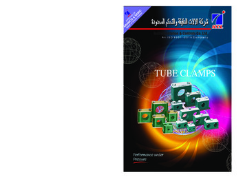
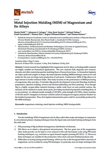
3 Casting and forging of wrought nickel and titaniumin the books above and in the lecture notes for first andalloys, and speciality steels; VIM, VAR, ESR, EBCHR second year.and open and closed die forging.4 The Sioux City air accident.Delivery Mode5 Phase metallurgy of titanium alloys.6 Titanium alloy microstructure engineering.David Dye’s lectures will be delivered by peer instruc7 Micromechanics of titanium alloys I.tion, as for MSE104 and MSE203. That is, students will8 Micromechanics of titanium alloys II; near-α, metastable first read the notes, watch videos of the exposition of theβ and CP Ti.material online, and read around the subject. Then, in theclass session we will discuss the topics raised by looking atsimple conceptual problems. Evidence suggests that thisresults in greater understanding of the material when thetime comes for revision and then better exam performance.Prof Paxton and Dr Vorontsov will lecture their parts ofthe course in a conventional fashion.Prerequisites and ReadingThe graduate, having completed their formal education, must be able to extend their knowledge from textbooks; indeed, the ability to self-educate based on thefoundations provided by a degree is the primary distinguishing feature of the graduate compared to the schoolleaver. And, in a course of this nature, the lectures canonly be the beginnings of the study. Indeed, for a fulltime degree over 32 weeks with each lecture courses comprising 1/8th of the year and 24 lectures, each lecture canfairly claim 32 40/(8 24) 6.7 h of a student’s time.Therefore even after accounting for revision and examination practice, and the lecture itself, significant out-of-classstudy should be the norm.For the titanium lectures the primary reference is GerdLütjering and Jim Williams excellent book, Titanium. Inaddition, the standard metallurgy references from first andsecond year remain of great utility. For the Ni, Al andsteels lectures then those lecturers will provide their ownguidance.Course Support and AssessmentThis section of the course is composed of 8 lectures. Itis examined in the summer exam (approx. one third ofthe exam). The materials provided consist of the lecturesand accompanying notes. Reading of the literature andtextbooks is encouraged.1. Introduction1.1. Materials SelectionFirst, lets consider how a designer chooses the optimalmaterial to use for their application; understanding thethought process will help the metallurgist to advise them,and to design more appealing alloys for future use. Wewill consider first airframe materials, before turning to gasturbines.Aeroplanes have, in one sense, remained very similarsince the dawn of the jet age in 1958; long pressurisedtubes with wings, onto which external podded gas turbineare mounted. But, over the last 20 years, there has beena slow revolution in aircraft manufacture as aluminium alloys have been replaced, at least in part, by composites andtitanium. Aircraft being introduced in the 2010s consumearound 25% less fuel (and hence produce 25% less CO2 )per passenger mile than the 1980s aircraft they replace;e.g. the B767 by the B787. Around half of this improvement is due to the airframe and half to improvements inthe engines, and in each of those cases around half of thoseimprovements are due to the materials. Thus, materialscontribute more than improved aerodynamics to the emissions reductions, and so materials understanding is a corecompetence for a successful aircraft or jet engine manufacturer.A new class of aircraft has also emerged over the last 20years, principally in the military sphere, of the unmannedaerial vehicle or UAV. Lacking pilots, it might be possible that such vehicles might be able to tolerate a greateraccident rate and hence, use less extensively qualified materials. In practice, the cost of avionics and design limit1 A Cottrell. An Introduction to Metallurgy, 2nd Ed.,Institute of Materials, London, UK, 1995.2 RE Smallman. Modern Physical Metallurgy, 4thEd., Butterworths, 1985.3 DA Porter and KE Easterling. Phase Transitionsin Metals and Alloys, 2nd Ed., Chapman and Hall,1992.4 GE Dieter. Mechanical Metallurgy, 3rd Ed., McGraw Hill, 1988.5 D Hull and DJ Bacon. Introduction to Dislocations,4th Ed., Butterworth-Heinemann, 2001.6 G Lütjering and JC Williams. Titanium, Springer,2003.Towards the end of the degree, students should also bestarting to prepare for postgraduate study, where readingand critically assessing research articles becomes normative. So in addition to the notes and lectures above, formany of the lectures I will also set a journal article to beread beforehand.The course is primarily designed for students who havealready done the first and second year of the Imperial materials degrees; therefore that background knowledge is assumed. Erasmus students and MSc students lacking thisbackground from their previous studies can find assistance2
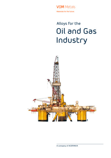
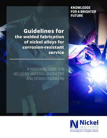
Figure 2: Schematic cutaway of the Rolls-Royce TrentXWB, theengine for the A350, which entered service in Dec 2014.Then, the air is mixed with fuel and burnt in the combustor. This comprises an inner chamber or flame tube,which is insulated by compressor air from the pressure casings on the inside and outside. There are also fuel injectors, etc. Burning of the fuel results in a temperature andpressure increase, taking the gas stream temperatures toabove 1600 C at entry to the turbine. The turbine thengradually increases in diameter as the gas cools and increases in volume, and power is extracted. Finally a hightemperature supersonic jet of air exits the rear of the engine. Mixing of this air with the bypass air helps reducethe jet noise.Thus, for different sorts of components different properties or degradation mechanisms end up being the limiting factor. For the wings or aeroplanes, often stiffness isthe limiting factor - the total deflection that can be tolerated. Landing gear are strength limited. Jet engine turbine blades are limited by creep - continuous extension atconstant load that would, left unchecked, result in contactwith the casing. Fan blades, on the other hand, are fatiguelimited. This can be either low cycle fatigue (i.e. flightcycles) or high cycle fatigue (‘flutter’ or vibrational modesat transient conditions on run-up or run-down). Nuclearpower station reactor pressure vessels are, absent irradiation embrittlement, LCF limited (the number of fuel poweroperational cycles).Turning back to a table from MSE104, recall that thevery best steels, aluminium alloys and conventional titanium alloys all have the same density-corrected (specific)Young’s modulus and strength. Therefore, at least to asimplistic analysis, its not strength or stiffness that leadsto the selection of one material over the other. It might bethe specific properties achievable at an acceptable cost so in the automotive industry there has been a continuousinnovation tussle between the steel and aluminium industries over the major structural components. Commonly,it might be the fatigue or other degradation mechanism-Figure 1: The Boeing 787 and X-45A (a demonstrator unmannedaerial vehicle) in flight.the utility of scrimping on material quality, but it shouldstill be understood that cost is a prime consideration formaterial insertion right across the aerospace industry, eventhough jet engines cost about as much, per unit weight, assilver.Turning to jet engines, the thermal efficiency of a turbine increases quite dramatically with temperature andfollows the form of T /Tmax , where Tmax is the turbine entry temperature and the base temperature must be greaterthan the environmental temperature of the heat sink, soapprox. 300K. Therefore the efficiency increases withTmax . However, the maximum temperature is very oftenlimited by the materials capability that can be providedin the operating environment. And, we want to use thelowest mass material we can, to avoid having to move allof that unnecessary weight. Therefore, we use differentmaterials in different parts of the engine that experiencedifferent temperatures.At the front of the engine, we suck in cold air fromthe air stream impinging on the engine. In a modern highbypass turbofan, 80% of this air is accelerated by the firstfew rows of blades - called stages - and is then ejectedaround the rest of the engine. Over time, fan diametershave tended to increase and the bypass ratio has increased,which improves the engine efficiency. The remaining air isthen compressed, in the succeeding stages, increasing itspressure and temperature. At some point, in the compressor, the temperature becomes so high that nickel superalloys must be used, for both the blades and the discs thatconnect the blades to the shaft that drives them.3
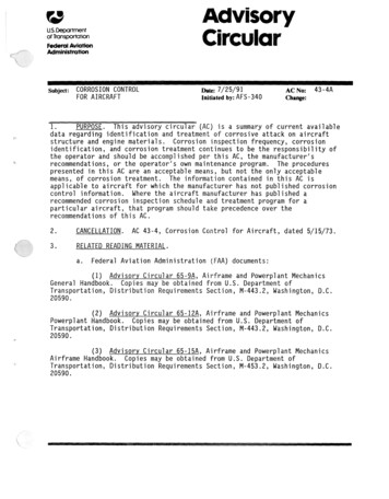
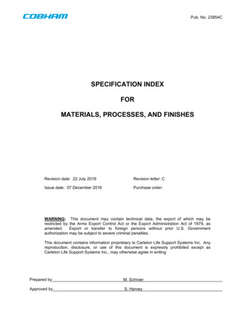
and fittings, problems can occur. Mostly this is resolvedby making such fittings out of titanium, which is corrosionresistant and modulus matches the composites.The other thing to remember about metals is that,more than strength or stiffness, their amazing propertyis their damage tolerance - their ability to resist catastrophic crack growth and instead to fail gradually, allowing time for inspection to discover growing crack and retirecomponents. Most ceramics (including carbon fibres them selves) have a fracture toughness K1c of around 1 MPa m,whereas even an ordinary steel has a K1c of 90 MPa m.We can also, to an extent, often optimise the materialprocessing to, at minimum, trade strength for toughness,allowing optimisation relatively late in the developmentphase. So, we see that the plane strain fracture toughness of both Al alloys and β-Ti alloys shows this relationship. We also see that, for aluminium alloys, controllingthe tramp Fe and Si contents that result in crack-initiating inclusions allows an increase of around 10 MPa m, whichis very significant for the strongest alloys used in aircraft.All of these discussions lead to the main point of thissection: there is more to materials selection than AshbyTable 1: Specific properties for some typcial aerospace materials.MaterialCFRPTi-5553Ti-647075-T6 (Al)A300M steelYoung’sModulusE GPa12011010570210YieldStregnthσy MPa120014009005502050Densityρkg.m 316004500450027007830E/ρMJ.kg 17524232627σy /ρkJ.kg 1750310200200262limited performance that can be achieved, with an affordable manufacturing route and using existing equipment.After all, for existing equipment the marginal cost of production os nearly zero, and this factor inhibits the adoption of new production technology.But, two stand-out factors from this table are apparent; high strength titanium alloys do have a higher specificstrength than any other metallic material, and are corrosion resistant. The other is that carbon fibre reinforcedpolymer composites can have triple the specific strengthand stiffness of conventional metallic materials.But, the march of composites hasn’t proceeded withoutupset. The F22 was supposed to be a mostly polymeric airplane, but it turned out that over the development phasemuch of the composite had to be replaced with titanium,with the same modulus and hence the potential for replacement without redesign. And so the F22 ended upbeing an astounding 42% titanium (by mass), mostly comprised of forged and machined components. Similarly, inthe B787 development, Boeing had problems with the wingspar root fixturing, which reveals the main design problemwith composites. Even if long fibre carbon composites canreliable be manufactured in such large pieces, they onlyshow their outstanding performance in tension along thefibre direction. Their shear and transverse properties arequite poor and so in triaxial stress situations, such as jointsFigure 3: The F22 fighter aircraft, the airframe of which is 42%Ti, 24% polymer matrix composite (PMC), 24% aluminium alloyand 10% steels. At the beginning of manufacturing development amajority PMC share was planned.Figure 4: Variation in fracture toughness with strength achievableby processing for (top) aluminium alloys and (bottom) β-Ti alloys.4
diagrams. In reality, for the highest performance, mostsafety-critical materials we use in society today, alloy design, manufacturing, component design and in-service support are tightly interlinked. These four, quite distinct areas of expertise must both be individually excellent andrelate well together for a world-leading engineering organisation to develop market-leading products. In addition, often a balance of properties must be maximised- including poorly-understood phenomena such as corrosion, erosion, oxidation and sulphidation performance, orweldability and manufacturability, or fatigue behaviour, orthe manufacturing value chain, together with the ‘simple’properties of strength and stiffness.whether the US will ever develop a new high temperature‘core’ of a fighter aircraft engine again, for example. For anew entrant to the market, the cost to develop an entirelynew engine architecture would undoubtedly be in the billions of pounds, and then the manufacturer would needto tolerate a poor safety record and uncompetitive fuelefficiency for 5 years of fleet operations to gain enough experience to make an iterative modification. On the thirdattempt, after an almost unimaginable outlay, a competitive engine might be developed. So this is a market withvery high barriers to entry.Turning to the engine architecture, as we said earlier,essentially the gas flow proceeds first through a fan, thenthe non-bypass air goes through the compressor, into thecombustor and then out through the turbine. The turbineextracts the energy to drive the fan and compressor. Twoor three concentric shafts are used, with the widest diameter, shortest shaft connecting the hottest, fastest spinning,highest pressure part of the turbine to the similarly hot,high pressure inner compressor. There are then the Intermediate (IP) compressor and turbine, and the low pressure(LP) fan/compressor and turbine. Having three shafts instead of two adds weight but allows for better thermofluidoptimisation of the stages.As the gas heats up, there is a transition from a titanium construction to nickel superalloys, at around 550 C,while the shafts are made of steel. The fan casing is also1.2. Jet enginesIn the titanium and nickel parts of the course, muchof the discussion will be around jet engine materials, forwhich is it helpful to have both some technical and industrial background. Rolls-Royce is a large UK corporate,with a market capitalisation of 14.3bn (Jan ‘11 figures),placing it in the middle of the FTSE 100. In 2010, itsearnings were 10.9bn (0.5% of UK GDP), approximately2/3rds of which were from civil aerospace, with a 10.2%operating margin and a 4.9% net profit margin. It holdsaround 40% of the market for large civil jet engines serving the twin aisle market, in a near-duopoly with GE, theworld’s largest industrial conglomerate and a major US defence contractor. In 2011, it had 40,300 employees, around22,000 of whom were in the UK, with a revenue of around 260k per employee per year; 50% of this revenue was inservices. It is the largest UK exporter on any measure,with a 900m annual R&D spend. It delivers around 900engines per year, with over half its installed base beingunder 10 years old, guaranteeing a service revenue streamfor decades to come; the order book backlog also stretchesnearly out of sight (e.g. 10 years). And it has nearlyzero net debt. And that’s before we start considering thesupply chain. If there is going to be a UK manufacturingrenaissance, we need Rolls-Royce to grow, and we needmore firms like it.It is particularly important to the materials R&D community because its products have that combination of strongdrivers to improve efficiency and low tolerance for failurethat can sustain high enough margins to drive research.So, a 0.5% improvement in operating efficiency is makeor-break for an engine order, costing an airline m in fuelper year. In contrast as a society we tolerate productionfailures in the automotive sector that kill thousands eachyear, and many will deliberately set out to purchase heavy,inefficient and slow vehicles for fashion (SUVs in Kensington, anyone?) And so in the steel and aluminium industry,there is relatively little investment in R&D, despite theirhigh production volumes, because there is so little profitmargin to pay for innovation.It is also important to realise that bringing a jet engineto market that is a close evolution of an existing enginecosts on the order of 0.5bn. There is serious doubt as toFigure 5: (top) Schematic showing the different parts of a jet engine,(bottom) numbers of stages and rotation speeds for the three shaftsin the Trent XWB.5
Figure 6: Evolution of pressure, temperature and gas velocitythrough the core of a jet engine. From Rolls Royce, ‘The Jet Engine.’Figure 8: B52 on takeoff. For a modern aircraft, no smoke is visible.important, as it must contain the fan blades in bird strike/ blade off scenarios. As important as the blades, the rotor discs that attach them to the shafts are so heavy thattheir fragments cannot be contained in the event of failureand therefore they cannot be allowed to fail and hazard theairframe. A disc failure due to a generic materials problemwould be very serious for the credibility of a gas turbinemanufacturer. Some approximate operating temperatures,stresses and lives are given in the Table.In a turbine blade, the temperature varies very significantly from the core of the blade, which is cooled, to thehot skin. The blade is also coated with a ceramic thermalbarrier; together the cooling air and thermal barrier coating bring the temperature down anywhere up to 500 C.As the blade creeps, the applied stresses redistribute suchthat the strong, cool core supports the majority of theload.One problem in aviation is that as we make planesmore efficient (at maybe 2% p.a.), and as the world economy grows, demand increases by about 5% p.a. (triplingin 20 years). Therefore, if we successfully complete anenergy transition to non-emitting sources in land-basedtransport, electricity production and space heating, aviation could grow from 12% of UK emissions today to be amajor contributor. And the problem is that kerosene hassuch a high energy density that its almost impossible toforeseen substitution (e.g. with hydrogen or batteries) onthe grounds of physics. Using crop-derived biofuel may bethe best we can do. In any case, as well as on industrialand economic grounds, there is a strong moral imperativeto improve jet engine operating efficiency.And to date, there has been continuous improvement.Since 1950, fuel burn per passenger km has decreased by70% and takeoff noise by a factor of 4 - an in addition wedon’t see trails of black soot any more. Seriously, checkout video of a B52 or a croaky old 747 and compare to anew airplane. So there is hope.1.3. LifingWe turn now to lifing, the process of establishing thesafe life of a component subject to fatigue loading. Recallthe form of a fatigue crack growth curve, with a threshold cyclic stress intensity factor Kth below which crackgrowth will not occur, where K σ πa, σ is theapplied cyclic stress and a0 is the initial flaw size. Oncethe crack begins to grow, a Paris Law type relationshipdawith dN C K m is found, and the crack grows until thefast fracture stress intensity K1,c is approached.Deterministically Safe Lifing.Now, say that we know the the probability distributionfunction of defects in the material will be. In most materials there will be some population of gas pores from castingand ceramic inclusions from the moods used for the liquidmetal. We could then estimate, for (i) a given desired failure rate, say 1 per 10 million takeoffs, (ii) a given materialreplacement rate (say 60,000 h or 8,000 flight cycles), (iii)a volume of material in the engine (say 2 tonnes), what thelargest inclusion would be that would have a 50% chanceof appearing at that frequency. Given that inclusion sizeFigure 7: Simplified section through a jet engine, showing the materials used in different locations.Table 2: Some approximate maximum operating temperatures andstresses for different components in a large civil jet engine.ComponentT CFan bladeIP compressor bladeHP compressor disc rimHP compressor disc boreHP turbine blade coreHP turbine blade skin404507506007001100Peak Stress Replacement MaterialMPaInterval550N 10,000 Ti-6Al-4V45020,000 hTi-624640020,000 hRR100060020,000 hRR100070010,000 hCMSX-420010,000 hCMSX-46
Figure 9: Schematic of a fatigue crack growth curve for an alloyshowing Paris Law behaviour.( 1 mm), we could then calculate the maximum stressthat could be applied without driving that flaw into fatigue crack growth at Kth . The problem would be thatno airplane could be made that could fly under such aconservative regime. Notice that, despite the term, thisapproach still requires knowledge of the (necessarily rare)occurrence of small defects in material produced by thetonne, including all the possible manufacturing variances.The historic, empirical approach that is actually usedis based on spin testing. Here, it is assumed that the distribution of component lives is log-normal. Then, a seriesof spin tests are performed to grow cracks, with periodicinspections to stop the test once a 0.75 mm crack is foundby non-destructive inspection. The mean and standard deviation of these lives is then found, and then mean decremented by 3σ to get a 1/750 life. For 3-8 components inthe test series, this is around 1/3rd of the expected meandisc life. Further safety factors are supplied by the timefor the 0.75 mm crack to grow to failure, and by periodicinspections mandated at overhaul intervals. Therefore, for20,000 cycle lives, and 6 critical assemblies in the engine, this approach gives a probability of loss of around0.4 per million flights.The problem with this approach is that first that it hasno mechanistic basis - a statistical assumption is made,and then empirical testing is used to establish a life. Theother problem is that the 2/3 of components are discardedlong before their actual service life. This is handy for thejet engine manufacturers, as it guarantees a nice servicebusiness, but otherwise just makes flying more expensivethat it needs to be (jet engine sales are a bit like razorblades - there isn’t much money in the engine, peoplemake money on the parts and service contract). Seocndly, its disheartening - implicitly, an acceptable level ofrisk is tolerated. Since the Vietnam war, the notion of corporations and governments taking risks with people’s liveshas become intolerable, particularly when the failures are‘newsworthy’ - intermittent and spectacular, rather thanFigure 10: Typical inclusion size distributions in a super clean, powder metallurgy nickel-base superalloy such as Rene 95, on (a) linearand (b) log-linear axes. Note that, for the volumes in a typical jetengine, the probability of a 0.5 mm size inclusion is actually quitehigh. From Reed, The Superalloys, p.265.everyday and mundane. This is true even if those risks aretiny compared to everyday hazards we willingly accept,like having our children killed by careless drivers (see C.Perrow, Normal Accidents).So, with the advent of fracture mechanics in the 1970s,it is worth asking if something better cannot be done. Fora given flaw size and stress, we can integrate the Paris Lawto obtain the life mda C K m C1 σ πadNWe then separate and integrate:Z NfZ aK1cdadN m/2m0a0C1 σ (πa)(1)(2)So the life Nf is given byNf 7hiaK1c1(1 m2 )aC2 σ ma0(3)
The first approach we consider is called damage tolerantlifing or retirement for cause. He, there initial flaw size isset to the limit detectable by non-destructive inspection,aNDI . Then, the toughness and applied stress are used todefine the critical flaw size at failure, acrit . The Paris Lawis then used to find out how long a crack would take togrow from aNDI to acrit , and inspection is then mandatedmore frequently than this interval. If, on inspection, acrack is found, then the part is retired, otherwise it is returned to service. Thus, discs are only retired when the iscause to do so.Figure 12: Variation in the expected cyclic life for different stressedvolumes, using a probabilistic approach to lifing for Rene 95. FromReed, The Superalloys, p.268.Figure 11: Illustration of the retirement for cause approach. TheNDI inspection limit and fracture mechanics are used to establishthe inspection interval; if no crack is detected at inspection thenthe assumed maximum crack size is re-set to the NDI limit and thematerial allowed to continue in service.This procedure subtly shifts the emphasis in designingan alloy towards increasing its fatigue crack growth resistance (the Paris Law coefficients), as for a given inspectioninterval determined by operational requirements this willbe the determinant of the operating stress than can betolerated, and hence the part weight and engine efficiency.It is argued that improving this so-called ‘damage tolerance’ is preferable to a futile effort to eliminate defectsand hence stay below Kth , which will tend to result inan unaffordable spiral of increasing costs.The problem, which we shall return to later in thecourse, if that it requires the inspection procedure to be execu
addition, the standard metallurgy references from rst and second year remain of great utility. For the Ni, Al and steels lectures then those lecturers will provide their own guidance. 1 A Cottrell. An Introduction to Metallurgy, 2nd Ed., Institute of Materials, London, UK, 1995. 2 RE Smallman. Modern Physic