Transcription
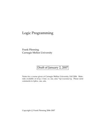
Session 3220A Course in Programming and Computer GraphicsUsing Visual C R.W. MayneProfessorDepartment of Mechanical and Aerospace EngineeringUniversity at BuffaloState University of New YorkBuffalo, NY 14260Phone: 716-645-2593 ext. 2254Fax: 716-645-3875Email: mayne@eng.buffalo.eduAbstractThis paper describes a course in computer graphics for seniors and graduate students inmechanical and aerospace engineering at the University at Buffalo. The course involves 3Dgraphics theory but also focuses on programming for computer graphics. It is taught in a PCWindows environment with Microsoft’s Visual C .The paper provides a brief history of the course and its relationship to our other computeraided design offerings. We discuss our strategy for introducing students to programming withVC including initial object-oriented exercises without graphics and then programmingapproaches for basic 2D graphics operations in windows. This is followed by an implementationof 3D graphics programming using an object-oriented format and, lastly, our approach tointroducing OpenGL for the PC.IntroductionFor many years, we have taught a computer graphics course for seniors and graduatestudents in mechanical and aerospace engineering at the University at Buffalo. This course is onein our series of courses in computer aided design and computer graphics. Other courses in theseries include a mechanical design course using AutoCad and ProEngineer for design (recentlymade a requirement for BSME students), a second ProEngineer course considering finiteelements, mechanisms and manufacturing, and a virtual reality graphics programming coursebased on workstation programming and including World Tool Kit. The course we are discussinghere is normally a prerequisite for the virtual reality course.Our computer graphics coursework originated in the days of Fortran programming andTektronix “green screen” computer terminals well before the popularity of CAD packages. Thisintroductory course to computer graphics programming has evolved through variousPage 7.37.1Proceedings of the 2002 American Society for Engineering Education Annual Conference & ExpositionCopyright 2002, American Society for Engineering Education
instructors, and hardware and software environments including UNIX and DOS. In recent yearswe have made a commitment to windows programming on personal computers using Microsoft’sVisual C .The VC programming environment has proven to be very satisfactory. Students whohave very little computer science background are able to adapt to C object-orientedprogramming and to the Application Wizard of VC . They are able to do their programming inour department PC laboratories, they can take their work home easily using their own computers,and the programs that they produce look very much like the commercial programs they useroutinely. At many points in the course there is the common reaction: “so this is the way it’sdone”. The course develops specific programming and theoretical skills in computer graphicswhich transfer to any computing environment. But, by exposing students to PC windowsprogramming, it also considerably broadens their computing skills.This paper summarizes the nature of our computer graphics course and the various topicsthat we cover. It also is intended to provide some insight into Visual C programming and theway that it can be integrated into a computer graphics course.Assumptions and BasicsThis course is a cross-listed course offered at the undergraduate level (MAE 473) and atthe graduate level (MAE 573) under the title Computer Graphics for CAD. Except for anoccasional special case, the programming backgrounds of the undergraduates and graduates aremuch the same. Typically they will have had an exposure to C programming (probably asfreshmen or sophomores) but have not done much programming recently. So we begin byreviewing C programming at the same time as the Visual C environment is introduced. TheApplications Wizard of VC is used for windows programming in the course to facilitateprogramming without requiring students to become involved in the complete nitty-gritty ofwindows details. However, we initially use the VC “Console Application” format. In this form,when a compiled and linked program is executed, it produces a DOS-like window with analphanumeric display without graphics capability. The programming, however, is quite simple. Itcan be done in a single file within the Integrated Development Environment of VC . Code canbe conveniently edited, compiled and linked. And program execution can be easily performedduring program development without leaving the environment.The Console Application format is very much appropriate for starting out in Visual C .It provides the place to revisit arrays and pointers (where students usually need work) and todiscuss object-oriented programming (which students only vaguely understand). This is the wayHorton’s¹ popular Visual C book begins. Other approaches, for example Gurewich andGurewich², that move quickly into windows programming without first developing these conceptstend to be less suitable for engineering applications. Two of our example programs using objectsare shown in Figures 1 and 2. These are the DOS windows of the Console Application format.The first of the programs in Figure 1 shows outputs from a “rectangles class” and a “circles class”by using appropriate member functions. In the program of Figure 2, the rectangles and circlesclasses are derived from a “TwoDobjects class”. Virtual functions are used here so that an arrayof TwoDobjects containing both the rectangle and circle objects can be manipulated easily.Member functions designed for rectangles or circles are automatically called as needed forspecific objects.Page 7.37.2Proceedings of the 2002 American Society for Engineering Education Annual Conference & ExpositionCopyright 2002, American Society for Engineering Education
Windows Programming ConceptsThe windows programming world is, of course, highly dependent on object-orientedmethodology not only for programming but for basic organization it self. Writing programs forwindows involves an incredible amount of detail, most of which is provided by functions andorganization built into the compiler and the operating system. Like many Microsoft products,nearly everything is available in VC but in such abundance that it can be hard to find the mostdirectly useful and interesting tools for an application. In this course we have tried to focus onthose things which are most basic for engineering graphics and calculations. As students learnthese basic tools and understand the VC environment they can move rather easily into otherVC capabilities.We have used the VC AppWizard executable form for our windows programsincluding the Document/View architecture. In this format, VC creates a program/projectstructure which serves as a template for the programmer’s application. If the six step AppWizardstart up process is followed, accepting all defaults for creating an AppWizard project, twenty fivefiles of C code are created by the AppWizard alone. Without any added code, the resultingproject can be compiled and linked producing additional files including an executable file. Whenexecuted, it will create a normal looking but blank window on the screen where nothing happens.Basically all of the VC prewritten code is used to put the blank window on the screen andprovide the resources so that application programming can begin. In many ways, this makesprogramming for windows much more like writing a part of someone else’s program rather thanwriting your own. Of course, plenty of work must still be done, but it requires an understanding ofthe environment and how to work within it.The Document/View architecture of the AppWizard provides a program organizationwhere data is considered to be part of a “document”. Most programming takes place in two C classes. One class is a Document class for storing and manipulating the data in the document.The other class is a View class for visually displaying the document data and for handlinginteractions with a program user. The Document and View classes are both derived from higherlevel classes and have access to many convenient functions, classes and resources through theVisual C libraries and the Microsoft Foundation Classes (MFC). These include the graphicscapabilities of OpenGL and Microsoft’s DirectX which both facilitate software/hardwareinteraction through advanced graphics cards.Beginning Windows ProgrammingProceedings of the 2002 American Society for Engineering Education Annual Conference & ExpositionCopyright 2002, American Society for Engineering EducationPage 7.37.3The View class of a project contains the functions designed to place information on thescreen and to interact with the user. The “OnDraw” function of the View class is called by thewindows operating system as a program begins execution and also every time that it needs toupdate or redraw the program window. Figure 3 shows the window for our first windowsprogram called “FirstWin”. It contains both graphics and text drawn by the OnDraw functionlisted below. OnDraw is a member function of the View class. In the FirstWin program, theView class was automatically given the specific name CFirstWinView by the VC AppWizardas shown in line 01 (the prefix “C” simply means “class”). The OnDraw function was alsoprepared automatically in template form by the AppWizard and originally consisted of lines 01 –05 and line 17 below. Line 05 provides the cue for the programmer to add his/her own code. Wehave added lines 06 – 16 and these are the only lines of code that have been added anywhere in
the FirstWin program. In the code, line 01 indicates that the pointer pDC is passed into theOnDraw function as it is called by the windows operating system. This pointer identifies thedevice context (i.e., the current window) where OnDraw should be drawing. Line 08 uses thepDC pointer to activate the TextOut function, placing "This is a Box and a Dot!" in the windowbeginning 25 pixels from the top of the window and 50 pixels from the left edge. Line 07declares a CString object called “Buffer” and line 09 formats Buffer to contain some text and thetwo integer variables that define the box center. Line 10 again uses the pointer pDC to identifythe window and then writes Buffer just below the box and dot phrase. Line 11 sets the pixel atthe box center and lines 12 – 16 actually draw the box.0102030405060708091011121314151617void CFirstWinView::OnDraw(CDC* pDC){CFirstWinDoc* pDoc GetDocument();ASSERT VALID(pDoc);// TODO: add draw code for native data hereint CenterX 300, CenterY 50;CString Buffer;pDC- TextOut(50,25,"This is a Box and a Dot!");Buffer.Format("The Dot is at %d, %d",CenterX, CenterY);pDC- TextOut(50,50,Buffer);pDC- SetPixel(CenterX,CenterY,0);pDC- MoveTo(CenterX - 25, CenterY - 25);pDC- LineTo (CenterX 25, CenterY - 25);pDC- LineTo (CenterX 25, CenterY 25);pDC- LineTo (CenterX - 25, CenterY 25);pDC- LineTo (CenterX - 25, CenterY - 25);}The OnDraw function above draws the window shown in Figure 3 very nicely but doesnot do anything else. In order to interact with a user, windows messages (which result, forexample, when a key is pressed or a mouse is clicked) must be processed or command functionsmust be developed to respond to clicks on the menu or tool bars. The appropriate functions can becreated through the VC ClassWizard and can be automatically introduced into the View classor Document class as desired. The function below is shown as an example of a mouse messagehandler in a simple drawing program called SimpleDraw. The View class in this case is calledCSimpleDrawView and this particular function (called OnLButtonDown) will be executedwhenever a left mouse click is received in the SimpleDraw window. Lines 01 – 03 and line 14were furnished by VC as the function was created. Lines 04 – 13 contain the code which hasbeen added.void CSimpleDrawView::OnLButtonDown(UINT nFlags, CPoint point){// TODO: Add your message handler code here and/or call defaultCSimpleDrawDoc* pDoc GetDocument();CClientDC aDC(this);aDC.SelectObject(&m BluePen);Proceedings of the 2002 American Society for Engineering Education Annual Conference & ExpositionCopyright 2002, American Society for Engineering EducationPage 7.37.4010203040506
0708091011121314int i pDoc- NumLines;aDC.MoveTo(pDoc- FPoint[i]);aDC.LineTo(point);pDoc- LPoint[i] point;pDoc- FPoint[i 1] point;pDoc- NumLines ;CView::OnLButtonDown(nFlags, point);}Line 04 obtains a pointer pDoc to the “document” that is being used to store data for the drawingbeing made. Line 05 associates the “client device context” aDC with the current window. Line 06gets a blue pen ready for drawing. Line 07 uses the document pointer to find the current numberof lines in the drawing. Line 08 moves to the first point on the current line (already stored in thedocument). Line 09 draws a line to the point just clicked. The variable “point” takes on themouse cursor position when the mouse is clicked as shown in the argument list of line 01. Then,lines 10 and 11 store the new point in the document both as the last point on the current line andalso as the first point on the next line. Finally, line 12 increments the line counter in thedocument. In this arrangement, the OnDraw function of the SimpleDraw program is coded so thatit redraws the whole set of lines from first to last when it is called by Windows as a resizing,minimizing or adjustment of the program window takes place.Figure 4 is an example of a mouse drawing program that has been extended todemonstrate the development of specialized menu bar and tool bar items. The VC resourcepackage makes each of these items readily definable and allows them to be associated withfunctions that will be activated by clicking on them. In this program, mouse clicks on menu itemsand drop down menu items activate functions which can change parameter values to adjust linecolor, line thickness, etc. The tool bar items are normally defined to act as shortcuts to the dropdown menu items.Further into WindowsProceedings of the 2002 American Society for Engineering Education Annual Conference & ExpositionCopyright 2002, American Society for Engineering EducationPage 7.37.5While the programming above becomes rapidly intricate, students are able to understandthe concepts very well. Although it’s not practical to have them program completely fromscratch, student assignments have been typically defined to begin with an example program fromthe wide set of examples that we have been developing. For 2D graphics, we have often askedstudents to develop a mini CAD system including circles, arcs, rubber banding, and evenincluding snap-to-grid operations for accurate drawings. Saving data to file is also included usingthe Serialize function from the Document class which provides access to the normal windowsfiling process. Programs similar to Figure 5 might often result from student projects. Thiscontains adjustable snap-to-grid, a multidocument format and a customized file extension Asshown in Figure 5, there are two open documents (2Sq.snp is the active one) and the file windowis Open ready to give access to another file.It is also possible to expand student horizons by including functions available for theiruse in programming. In the 2D graphics world, a possibility that we will explore in the nextoffering of MAE 473/573 will be the inclusion of classes and functions for drawing graphs aspart of the example program files available to students. We currently have a basic 2D curveplotting function as well as a color contour plotter to use, for example, in plotting temperature or
stress distributions. Figure 6 contains representative graphs for an end-loaded beam. The beamsketch was created with a version of the mouse drawing program. The plot of beam tensile stressand the stress contour plot were drawn in the View class OnDraw function using the graphplotting tools and based on data generated by program code in the OnNewDocument function ofthe Document class. This function executes as the program starts.Graphics in 3DOne difficulty in teaching computer graphics is to decide how much canned software tomake available to students and how much individual programming is required by students. Ifstudents are required to program everything from scratch, too much effort is required even formodestly interesting programs. On the other hand, if too many “black box” functions are used, itis possible for students to create impressive programs while avoiding important programmingissues and theoretical details of computer graphics such as those in Foley and van Dam³.In dealing with 3D graphics we have made a successful compromise by making basic 3Dclasses and functions available to students. The complete coding for these classes and functionsis contained in example programs and is used for in-class discussion of theory and programming.Students are also asked, as part of their programming projects, to modify and extend the code inthe existing examples. These modifications have included the removal of hidden lines in aprojection algorithm, the improvement of 3D rotation functions, and the creation of 3D solidrepresentations for extrusions and bodies of revolution. The object-oriented programmingstructure of C used in the examples makes it quite easy to focus on particular parts of theprogram and consider the applicable theory.To generate 3D solid objects, we have used a series of derived classes to represent theobject. The first class is the BasePoint class which contains the global coordinates of the objectin three dimensions. The second class is the Points class which contains all of the verticesrepresenting the object in local coordinates (relative to the BasePoint). The third class is thePolygons class which defines each of the polygons forming the solid in terms of the vertices.Finally, the Shapes class is used to describe any specific shape by defining its base point, verticesand polygons. A shape can be easily translated by changing its base point, it can be rotated byrotating its vertices and it can be displayed by projecting and drawing its polygons. The codefragment below is taken from the declaration of the Shapes class to provide an indication of theorganization. In line 01 you can see that Shapes is derived from Polygons (which is derived fromPoints and BasePoint). Line 03 is the empty Shapes constructor function and lines 04, 05 and 06show the argument list for the function which actually defines an object shape. The base pointcoordinates are included in the argument list, the number of vertices (NPts), pointers to thevertex coordinates, number of polygons, number of points per polygon, etc. Coding is not shownclass Shapes : Polygons {public:Shapes(){};void Shapes::AdjustShape (double Xbp, double Ybp, double Zbp, int NPts,double* ptX, double* ptY, double* ptZ, int NPolys, int* ptNPPts,int* ptMPPts){ .}void Shapes::RotateX(double thetaX){Points::PRotateX(thetaX);}Proceedings of the 2002 American Society for Engineering Education Annual Conference & ExpositionCopyright 2002, American Society for Engineering EducationPage 7.37.60102030405060708
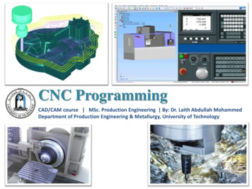
09101112131415161718void Shapes::RotateY(double thetaY){Points::PRotateY(thetaY);}void Shapes::RotateZ(double thetaZ){Points::PRotateZ(thetaZ);}void Shapes::Move(double nx, double ny, double nz){Basepoint::MoveBP(dx,dy,dz);}void Shapes::Dmove(double dx, double dy, double dz){Basepoint::DmoveBP(nx,ny,nz);}void Shapes::Show(CDC* aDC){Polygons::Trace(aDC);}for this function. However, lines 07 – 18 do show complete functions for the rest of the Shapesclass. For example, lines 07 and 08 will rotate a shape about an X axis through its base point bysimply calling the Points function which rotates all of its vertices. Lines 13 and 14 can move ashape in three dimensions by calling the BasePoint function which changes the base pointcoordinates. The Show function of lines 17 and 18 displays the shape on the screen by calling thePolygons function which carries out the drawing of each polygon.This program structure has proven to be very robust and useful. Projection algorithms canbe studied by focusing on the Polygons function “Trace”. This has been done for hidden lineremoval and for stereo projection. Higher level shape constructors have been easily written forcylinders and bodies of revolution. And a Bezier curve class has been written which makes useof the BasePoint and Points classes. Students can explore the coding in particular functions andassignments can be conveniently made to modify or improve the code. Figure 7 shows somesimple 3D projections made from the basic programs. Figure 8 shows a display from a versionwith hidden line removal and Bezier curve capability.OpenGLProceedings of the 2002 American Society for Engineering Education Annual Conference & ExpositionCopyright 2002, American Society for Engineering EducationPage 7.37.7For advanced level graphics on a personal computer, it is ultimately necessary to useOpenGL (Silicon Graphics) or DirectX (Microsoft). These software packages operate inconjunction with compatible graphics cards which allow hardware implementation of graphicsfunctions. The software will let the hardware function at its limit and fill in with softwareimplementation where necessary. We have been successful in incorporating OpenGL capabilityinto this course and into our set of program examples for the course. We have found the officialOpenGL guide 4 to be useful for OpenGL programming issues. The SuperBible 5 and the tutorialby Oursland 6 are especially useful for working with OpenGL in a PC environment. These laterreferences offer strategies for inserting OpenGL graphics into the AppWizard. Interestingly ithas been possible to adapt our object-oriented 3D graphics discussed above almost directly intoOpenGL graphics and achieve impressively quick rendering. We will not attempt to discuss theimplementation detail here. But, with modest modification of our Polygon “Trace” function,OpenGL commands can be used directly. The overall result is that 3D shapes can be easilygenerated, moved, rotated and displayed with our object-oriented programming tools. The higherlevel OpenGL programming tends to control viewing position and angle, lighting, backgroundcolor, etc.Figure 9 shows a first OpenGL program with the cylinder and box of Figure 7. In Figure9, the OpenGL shading quality and ability to remove hidden surfaces by depth buffering is very
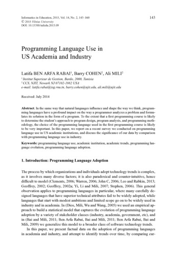
clear. With this capability it is reasonably easy to produce quality graphics and animations. Thedriving simulator of Figure 10 is an example discussed in class and which students can modifyfor their own projects. The number on the car hood in Figure 10 is an example of a studentmodification where the texture mapping necessary to place the number on the hood wasintroduced as part of a final project for the course. The roller coaster animation of Figure 11 isanother example of a student course project. In this animation, a six car roller coaster follows thetrack and can be viewed from adjustable positions including the front seat. The robot of Figure12 is a further example. It can be moved in steps or animated and can pick up the small objectshown near its gripper.ConclusionsThis paper has presented an approach to teaching computer graphics in a PC Windowsenvironment. The course has been quite successful and of interest to both seniors and graduatestudents. It provides an exposure to the process of windows programming in general and into theoperation of both CAD and computer animation programs. In addition, the course serves thepurpose of preparing students for further study and research in computer graphics.The paper is also intended to provide some insights into the process of Visual C programming and an indication of programming approaches for basic two-D graphics operations.A strategy for using object-oriented 3D graphics in instruction has also been described. Thisprocess is attractive for being able to allow students to inspect and modify functions whichservice different aspects of creation, manipulation and display of 3D representations. Thestrategy extends directly into the higher-level graphics capabilities of OpenGL where significantanimations and simulations can be conveniently developed.In terms of scheduling - students typically complete the 2D graphics project about halfway through the course. Lecturing on 3D graphics begins at about the 40 percent point. Two 3Dgraphics projects are also required. One is a specifically defined project performed withoutOpenGL and one is a student selected project using OpenGL.Bibliography1. Horton, I., Beginning Visual C 6, Wrox Press Ltd, Birmingham, UK, 1998.2. Gurewich, O. and Gurewich, N., Teach Yourself Visual C in 21 Days, Fourth Edition,Sams Publishing, 1997.3. Foley, J.D., et al., Computer Graphics Principles and Practice, Second Edition, AddisonWesley, 1990.4. Wright, R.S. and Sweet, M., OpenGL SuperBible, Second Edition, Waite Group Press, 2000.5. Woo, M., et al., OpenGL Programming Guide, Third Edition, Addison Wesley, 1999.6. Oursland, N.A., Using OpenGL in Visual C , www.DevCentral.Iftech.com.Page 7.37.8Proceedings of the 2002 American Society for Engineering Education Annual Conference & ExpositionCopyright 2002, American Society for Engineering Education
Figure 1. Object-Oriented ConceptsFigure 2. Object-Oriented with Pointers and Virtual FunctionsPage 7.37.9Proceedings of the 2002 American Society for Engineering Education Annual Conference & ExpositionCopyright 2002, American Society for Engineering Education
Figure 3. First Graphics in a WindowFigure 4. Drawing with the Mouse andCreating Menu and Toolbar ItemsPage 7.37.10Proceedings of the 2002 American Society for Engineering Education Annual Conference & ExpositionCopyright 2002, American Society for Engineering Education
Figure 5. Drawing in a MultiWindow EnvironmentProceedings of the 2002 American Society for Engineering Education Annual Conference & ExpositionCopyright 2002, American Society for Engineering EducationPage 7.37.11Figure 6. Mouse Drawn Sketch with Program Drawn Graphs
Figure 7. Simple 3D ProjectionsFigure 8. A Bezier Curve and Removed Hidden LinesPage 7.37.12Proceedings of the 2002 American Society for Engineering Education Annual Conference & ExpositionCopyright 2002, American Society for Engineering Education
Figure 9. Starting with OpenGLFigure 10. Basics of Driving SimulationPage 7.37.13Proceedings of the 2002 American Society for Engineering Education Annual Conference & ExpositionCopyright 2002, American Society for Engineering Education
Figure 11. Student Roller Coaster ProjectFigure 12. Student Robot ProjectPage 7.37.14Proceedings of the 2002 American Society for Engineering Education Annual Conference & ExpositionCopyright 2002, American Society for Engineering Education
programming, it also considerably broadens their computing skills. This paper summarizes the nature of our computer graphics course and the various topics that we cover. It also is intended to provide some insight into Visual C programming and the way that it can be integrated into a c