Transcription
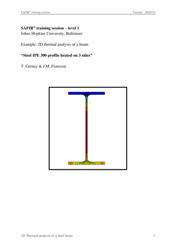
SAFIR training sessionTutorial – 06/2018SAFIR training session – level 1Johns Hopkins University, BaltimoreExample: 2D thermal analysis of a beam“Steel IPE 300 profile heated on 3 sides”T. Gernay & J.M. Franssen2D Thermal analysis of a steel beam1
SAFIR training sessionTutorial – 06/20181. General descriptionThis example deals with a 2D thermal analysis of a steel beam profile.General data:- Section IPE 300- Material model from Eurocode 3 part 1-2- Exposed to ISO fire on 3 sides- In contact with atmosphere at 20 C on the upper sideThe section file will be used for a subsequent 3D structural analysis. Therefore, it will alsoinclude a torsional analysis.2. Create a project in 2D for Thermal AnalysisFrom the pull down menu select:Data - Problem type - SAFIR2016 - Safir Thermal 2dTo save the project select (or use icons on the left):Files- Save or or [Ctrl s]Enter a file name, e.g.: IPE300GiD creates a directory with the name IPE300.gidGiD creates a number of system files in this directory.When you start the SAFIR calculation the Safir . IN, .OUT and .TEM files will be createdin this directory.Note: the project’s name cannot contain spaces or special characters. Regarding the namesof the files, SAFIR is not case sensitive.2D Thermal analysis of a steel beam2
SAFIR training sessionTutorial – 06/20183. Create the geometry in the xy-planeFrom the pull down menu select:Cross-Section- I-ProfileSelect IPE as type, IPE 300 as Profile, tick exact shape.Click on ApplyNote: GiD-Safir will create an IPE300 profile. The center of this profile will beautomatically centered on the 0,0 point of the xy-plan.GiD displays this profile.The blue lines represent the contour of the section, while the pink lines represent thesurfaces delimited by the blue lines. For instance, blue lines are used to assign thermalboundary conditions to the contour of a cross-section, while the pink surfaces are used toassign thermal properties to an area of the cross-section.2D Thermal analysis of a steel beam3
SAFIR training sessionTutorial – 06/20184. Assign the thermal boundary conditionsIn GiD, from the pull down menu select:Data- ConditionsThis window appears in GiD:2D Thermal analysis of a steel beam4
SAFIR training sessionSelect theTutorial – 06/2018button (“Line”). On the first pull down list, select: Frontier constraintsDifferent time-temperature curves are predefined. Select FISO for the ISO 834 fire curve.Click on the Assign button and assign it to profile lines as shown below.Press [Esc] or click on Finish to confirmSelect DRAW- Colors in the Conditions dialog box to display the frontier constraintsPress [Esc] or click on Finish to leave this view mode2D Thermal analysis of a steel beam5
SAFIR training sessionTutorial – 06/2018Then select F20 as temperature curveAnd assign it to the upper line of the profile, as shown below:2D Thermal analysis of a steel beam6
SAFIR training sessionTutorial – 06/20185. Assign a torsion constraint (for the torsional analysis)In GiD, from the pull down menu select:Data- ConditionsSelect thebuttonOn the pull down list: Torsion constraintsTick the box Constraint (only in GiD problem types versions prior to 1.4)Select the node on the vertical axis of symmetry of the steel profile. Validate with Finish.2D Thermal analysis of a steel beam7
SAFIR training sessionTutorial – 06/20186. Assign the materialsFrom the pull down menu select:Data- MaterialsSelect STEEL from the dialog box pull down listThe Thermal tab is active.Then select:STEELEC3EN as Material TypeA Convection Coeff hot of 25A Convection Coeff cold of 4A Relative Emission of 0.7Then select the Mechanical tab. Input:A Young modulus of 210 000 MPaA Poison ratio of 0.3A Yield strength of 355 MPaClick on Assign- Surfaces and assign it to the IPE300 surfacePress [Esc] or Finish to confirm.2D Thermal analysis of a steel beam8
SAFIR training sessionTutorial – 06/2018Select DRAW- all materials in the Material dialog box to display MaterialsPress [Esc] or Finish to leave2D Thermal analysis of a steel beam9
SAFIR training sessionTutorial – 06/20187. Assign the general dataFrom the pull down menu select:Data- Problem DataIn the Problem Data dialog mask enter:TIMESTEP, UPTIME, TIMEPRINT as neededDo not forget to tick the box Autorun Torsion AnalysisAlso tick the box Consider reduction of torsional stiffness and leave the value as 0.1Click on the Accept data buttonNote: The global center of coordinates (0,0) is by default positioned at the center of the steelprofile. This position can be adjusted here to consider the relative position of the steel profilewith respect to the rest of the structure in the structural model.2D Thermal analysis of a steel beam10
SAFIR training sessionTutorial – 06/20188. Create the meshSelect Mesh- Generate mesh or use [Ctrl g]Enter 0.0075 as size of elements to be generatedValidate with OKClick on View mesh to visualize the mesh9. Start the calculationFrom the pull down menu select:Calculate- Calculate windowClick the Start buttonClick the Output View buttonGiD creates a .IN file in the project directory and starts the calculation.In the output window you can see the calculation progress from SAFIR and the GiDinterface program which generates GiD postprocessor files from the .OUT file.2D Thermal analysis of a steel beam11
SAFIR training sessionTutorial – 06/2018Click on “Ok”, save, and open the postprocessor Diamond to visualize the results.2D Thermal analysis of a steel beam12
- Exposed to ISO fire on 3 sides - In contact with atmosphere at 20 C on the upper side The section file will be used for a subsequent 3D structural analysis. Therefore, it will also include a torsional analysis. 2. Create a project in 2D for Thermal Analysis From the pull down menu select: Data