Transcription
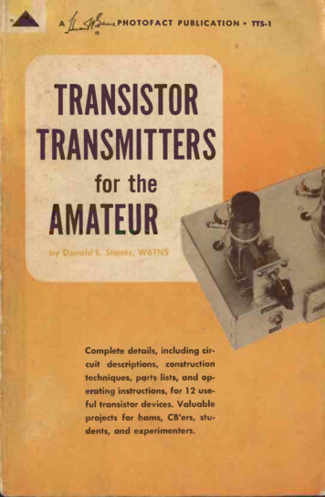
4,.2PHOTOFACT PUBLICATION TTS-1TRANSISTORTRANSMITTERSfor theAMATEURComplete details, including circuit descriptions, constructiontechniques, parts lists, and operating instructions, for 12 useful transistor devices. Valuableprojects for hams, CB'ers, students, and experimenters.
k
TRANSISTORTRANSMITTERSfor theAMATEURby Donald L. Stoner, W6TNSHOWARD W. SAMS & CO., INC.THE BOBBS-MERRILL COMPANY, INC.IndianapolisNew York
PrefaceFIRST EDITION1964FIRST PRINTING - FEBRUARY,NOVEMBER,1966SECOND PRINTING Co., Inc., IndianCopyright 1964 by Howard W. Sams &Statesof America.apolis, Indiana. Printed in the UnitedReproduction or use, without expressAll rights reserved.any manner,pictorial content, in withpermission, of editorial orliabilityrespectis assumedis prohibited. No patentherein.information containedto the use of theNumber : 63-23372Library of Congress Catalog CardAmateur radio has served to introduce thousands of enthusiasts to the field of electronics. For many, amateur radio is thestart of a rewarding profession; for others, it is a helpful supplement to their formal education in engineering.Constructing your own equipment is a satisfying and educational segment of the hobby. Also, you can keep abreast of thelatest developments in circuits and components at littleexpense.Construction projects for the beginner, as well as for theexperienced ham, are described in this book. Included areprojects for novice, technician, general -class, and Citizens -bandlicensees.For example, the "Novice Powerhouse" in Chapter 5 is anideal rig for the beginner or the QRP general -class operator.The modulator described in Chapter 6 can be added to the"Novice Powerhouse" for phone operation. The 10 -meter rigin Chapter 8 can be used to communicate over distances ofthousands of miles under proper conditions.The latest design and construction techniques are incorporated throughout, including transistor circuitry and circuit board layouts.Every piece of equipment has been built and thoroughlytested on the air. I hope that you will enjoy building andoperating these projects as much as I did preparing them forthis book.DONALD L. STONER, W6TNS
ContentsCHAPTER 1TRANSISTOR TRANSMITTERS ARE DIFFERENT7History of transistor development, power and heat dissipation,transistor packaging, high -frequency operation, transistor parameters, circuit configurations, power supplies, bias, and testing and alignment.CHAPTER 229OSCILLATORSTickler -coil oscillators, Hartley oscillator, Colpitts oscillator,Clapp oscillator, oscillator stability, crystal -controlled oscillators, and overtone oscillators.CHAPTER 349BUILDING OSCILLATORSBuilding and testing a crystal checker and calibrator, an 80/40 -meter "Peanut Whistle," the CB Cyclone, and recommendedtransistor types.CHAPTER 4POWER AMPLIFIERS61Flywheel action, frequency multiplication, interstage coupling,collector matching, the "Peanut Whistle II," and the "CBCyclone II."CHAPTER 5THE NOVICE POWERHOUSEHow it works, construction, adjustment, and operation.77
CHAPTER 689modulation, collector moduFrequency modulation, amplitude build a half -watt modulalation, build a low -power modulator,construction, and testing.MODULATION1tor, build a 5 -watt modulator,CHAPTER 7111TUNNEL -DIODE TRANSMITTERSHow it works, the tunnel diode,construction, and adjustment.build a 60 -second transmitter,CHAPTER 8121HIGH POWER FOR CB OR 10 METERS and obtaining componentsHow it works, construction, testing,TransistorTransmittersAre Different127INDEXThere is always an element of glamor and just a little extrathrill when operating a short-wave transmitter that employsno vacuum tubes. This is particularly true when you are usingit to communicate with someone several.hundred or even athousand miles away.Before plunging into the construction and operation of thesesolid-state "peanut whistles," let's review a bit of theory toobtain a clearer understanding of how they work. Even if youare an "old pro" in building rock -crushing tube rigs, transistortransmitters are different. Let's see why.THE HISTORY OF COMMUNICATIONS TRANSISTORSAlthough it may not be immediately obvious, much creditshould be given to the computer industry for the great progresswhich has been made in the field of communications transistors.In the mid -1950's there were few manufacturers who had theforesight to see the vast potential of the transistor for eliminating vacuum tubes in communications equipment. Theyseemed content to fabricate noisy, delicate devices suitable foruse in raspy -sounding portable radios.7
be a poor second comparedtoEarly transistor devices provedcommunicationstransmitters.to the vacuum tubes used inhigh -power, high -frequencyFor several years it appeared thatto fabricate. Fortutransistors were theoretically impossible this has not provednately for the communications industryto be the case.was enthusiastic about thisThe computer industry, however,immediately visualized the possinew electronics infant. Theythousandsof heat-generating andbility of eliminating thecomputer. Some of theinefficient tubes used in a typicaltable -top computers"dreamers" went so far as to predictsecretary orwhich could be operated by an average( Fig. 1-1)The designers could not tolerate such sluggish performancein equipment which had to make hundreds of thousands of"decisions" every second. Transistor manufacturers were askedto make faster and faster switching devices in order to raisethe IQ of the next model computer. Devices were also neededONTDOFFDELAY TIMETR RISE TIME FALL TIMETFTR- TDTDONbookkeeper.OFFFig. 1-2. Rise, fall, and delay time characteristics.which would deliver watts of power, rather than milliwatts ormicrowattg, in order to drive memory cores in the complexelectronic cerebral cortex of the computer.This constant pressure on transistor manufacturers forFig. 1-1. Transistor IBM 1620 computer.of the tubes in theThe transistor was able to replace many but the designersslower and less "intelligent" computers,shortcomings. Whenhad manysoon found that the transistorwas accomplished ratheron,"theprocessinstructed to "turninstructions was overcome,slowly. Once the delay in followingand continuedthe "turn-off" signalit was reluctant to obeymicroseconds.timecharacteristicsTheto plod along for severalare illustrated in Fig. 1-2.faster and more powerful devices brought about a revolutionin the semiconductor industry. Vast sums were invested inresearch program.13to perfect new ways of making better transistors for less money. The infant industry progressed from thehumble junction transistor, through the drift field, the diffused,and the mesa, to the present-day planar transistor, a miracleof semiconductor technology.Modern transistors are able to operate at the speed of light.A planar computer transistor is capable of switching from theoff state to the on state in less time than it takes the lightreflected from this page to reach your eyes (remember thatlight travels at the speed of 186,000 miles per second). Todayit is possible to purchase devices which deliver 20 watts or moreof radio -frequency energy while switching on and off 50 milliontimes (50 megacycles) each second. Although these transistorsare very expensive, they are available. Further pressures onthe semiconductor industry, and the ever increasing com98
reduced prices of comit, will result in greatly rate of progress conpetition withintransistors. If the presentmunicationsto buy a device which willtinues, it will soon be possibletube for less than 10.perform the same as a 6146POWER AND HEAT DISSIPATIONwishes to make a more powerful vacuumIf a manufacturerand encloses them in a largertube, he employs larger elements capacitance may increase,bottle. Although the interelectrode will be the same as thatgenerally speaking, the performance that the larger tube willof a physically smaller tube, exceptwithout damage. Unfortunatelybe able to handle more powerthis is not the case with transistors.lossless device, it will alwaysSince the transistor is not ais passed through it. Its design,produce heat when a currentimproved manufacturingwhich minimizes these losses throughridofthe heat once generated,techniques, and its ability to getof the transistor.determine the power-handling abilitymaterialand the junction largerMaking the amount of activebutitalso impairs its high decreases losses in the transistor,techniques must be employedSpecialjunction tofrequency performance.low while maintaining a largerather weirdto keep capacitancesresults in someand thedissipate heat. Often this conflictsuch as the "comb," the "star,"internal structures,"snowflake."power transistor (Fig.If you have ever torn apart a largepiece of semisurprised to see the tiny1-3) you may have beenmetal slug which cominside.Thelargeconductor materialis designed to draw heat fromwhich theprises the case (usually copper)through the heat sink on tend tothe junction and radiate ittemperature will always out oftransistor is mounted. Theheatwill tend to be drawnequalize and, in effect, the metal to which it is attached.the junction into the coolerare concerned, the junctionWhere operating life and reliabilityis the single most importantofthetransistortransistor transmitters,temperaturetemconsideration. When building or usingshould be placed on the operatingAsa"ruleparticular importanceit as low as possible.perature of the device to keepshouldbe mounted on at least 10of thumb," the transistor10Fig. 1-3. Construction of a typical transistor.square inches of copper or aluminum for every watt of powerinput. It is preferable to use commercial heat sinks (Fig. 1-4)which compress 100 square inches into a space of approxi-mately 2" x 3" x 4". Never run the transmitter at its maximum power level in an effort to get the last possible watt intothe antenna. Remember, if the power output is reduced byhalf, it only causes a loss of one "S" unit on a distant receiver.Experimental evidence indicates that for every 10 C. that thejunction temperature is reduced, the expected life span of thedevice will be doubled.How hot can a transistor get? That depends entirely on themanufacturer's rating, which is determined by the package the11
ADIAinre --.1DIA.185MAX009 .002-.001125TI 5 MINDIAcil DIAHu {fr-.230100EMITTER.242-BASE.278.200.0419045heat sink.Fig. 1-4. Commercially built-6.209200the type of material ittransistor chip is mounted in, and on should not feel heatspeaking, one-18 case (Fig.is composed of. Generallydevice in either the TO -5 or TOin a germanium devices in the diamond or round case (TO -31-5). Germaniumshould never be painful to touch,and TO -36, respectively)safely around 130 F., whicharealthough they are often operatedof pain. Silicon transistorsthethresholdthanareis just belowmuch higher temperaturesTO -5 andoperationatcapable oftransistors in thetransistors. Siliconat 130 F. or higher.germaniumTO -18 package can safely be operatedwhichcanbe mounted on ainpackagesSilicon transistorsbeyond the temperature pointheat sink often are operatedto touch.where they are painfultheir maximum tempertransistorsWhenever you use remembernearthat it is excessive junctionature rating, alwaysthe transistor, and the junctionthan the case.temperature that destroystemperatureitself will always be at a highertemperature can rise suddenlyMore important, the junction the increased temperatureand destructively long beforereaches the outside of the package.500- M- IN.017COLLECTOR.100(B) TO -18 outline.(A) TO -5 outline.100 .01TYPE NoDATE CODEMAX DIA250,.- 005.36 tMAX30M,12MN MU 77-4-312MAX.500375.C". DIA.052us, - -010EMITTER4,0.010.710.610.140 MAX DIA'INSULATEDLOCATOR PIN.072 MIN--I.410.32.140MAXNF -2A THREADBASEt- .010Y .005215.156RASEHIGH -FREQUENCY OPERATIONof high -frequencyVacuum tubes are excellent amplifiers is capable of veryfor example,radio energy. The Nuvistor,low cost. The primary limitingperformanceatin vacuum tubes areimpressivefactors of high -frequency performanceand transit time; that is, thethe interelectrode capacitancesreach the anode after leaving thetime it takes the electron tocathode.12302, 07r15 -0.2EMITTER.340920 1.1 . 1(C) TO -3 outline.(D) TO -36 outline.Fig. 1-5. Typical transistor cases.13
transistors, although it is comA similar condition exists inthe junctions are in intipounded many times. For example,attached, and they generallymate contact, being physically(Ce on the data sheets) . To makeexhibit a high capacitanceinto the transistor mustmatters worse, the signal injected (called Rb) to reach theelectrode resistancepass through theC forms a tiny low-passjunction. The presence of both R andof high -frequency signalsfilter which inhibits the amplificationThe fact that the electrons must negotiate through( Fig. 1-6) .a much lower frequency of, say, 1,000 cycles. The term expresses the loss of gain in the common -base configuration andis not valid for the more useful common -emitter circuit. Further, unless input and output impedances are known, it is notpossible to determine power gain. The alpha -cutoff frequencycurve for a typical transistor is shown in Fig. 1-7. It should be6 db PER3 dbOCTAVEzTRANSISTORSIGNALSIGNAL INFREQUENCY---labFig. 1-7. Alpha -cutoff frequency curve.INRbSIGNAL SIGNALfilter.Fig. 1-6. Rb and Ce form low-passconfines of a vacuumrelatively effortlessa solid rather than theall the carriers reach the collec-tends to slow them down. Nottravel different paths and tend totor at the same time; they accounts for the inability of thedisperse. This storage effectinstantaneously. As the fretransistor to follow instructions reached where the transistorita point isquency is increased,whetherto turn on or off, and as a resultdoes not knowdoes nothing.generally becomes quite conThe transistor experimenterhave arisen in an effort to definefused with all the terms thatAt one time itperformance of a transistor.the high -frequencythe alpha -cutoff frequency (fab)was necessary to know only possible to predict roughly howBy knowing this figure, it wasfrequency, and one transistora transistor would work at a givensimply definedAlpha cutoff isdowncould be compared with another.current3 db fromgain isas the frequency at which the14pointed out that frequency is shown on a log scale which makesthe high -frequency gain appear to fall off quite rapidly.Another term which expresses the high -frequency operationof a transistor is ft, the gain -bandwidth product frequency. Itis a convenient figure, for, as a "rule of thumb," it reveals thegain of the transistor at any particular frequency. For example,a transistor with an ft of 60 would have a power gain of 2 at 30mc, 4 at 15 mc, 8 at 7.5 mc, etc. Thus, by knowing the frequencyand the desired power output it is possible to approximate thedriving power required.A third term, Lt.) will probably become the industry standard; this term is defined as the theoretical or computed maximum frequency at which the transistor is capable of oscillation.Therefore at fn,a, the power gain is equal to unity and the deviceis not capable of amplification.The high -frequency characteristics of a typical transistor,such as the Philco Micro Alloy Diffused (MADT), is shown inFig. 1-8. Note that it has a flat portion where gain is relativelyconstant. However, as the frequency is increased, a point isreached where the internal workings of the transistor combineto oppose the amplification of high frequencies. Above thispoint the power falls off at a rate equal to 6 db/octave. Eachtime the applied frequency is doubled, the power gain dropsby 6 db. The point where the rolloff curve intersects the unity gain line is known as Lit,.15
leads can be heated, as in dip -soldering of printed -circuitboards, for as long as 10 seconds without internal damage. All70- 60"fi50z 40c.66 db PER OCTAVE20 db PER DECADEFREQUENCY302 e 100maxmax100characteristics ofFig. 1-8. High -frequencytypical transistor.or f,,, it would seemIf one works back from unity gain at some low frequency.possible to achieve infinitely high gaina modern high -frequencyAs Fig. 1-8 shows, this is not the case;than50 db of gain. Maxicapableofmoretransistor is easilyin Fig. 1-8) is a function of themum available gain (MAGimpedances. However,device current gain and the operatingin so small a space50 db of radio -frequency gain concentrated impossible to tamevirtuallytends to be highly unstable andneutralizationand shieldingcomplexwithout extremelyusually held down to 40schemes. For this reason gains aremismatching in the input or outputdb/stage by impedanceis usually consideredcircuit, or in both. Thus the 40-db figure Although some powerto be the maximum useful gain (MUG) . reduced circuit comgain is lost, the increased stability andplexity make it a small price to pay.assumed and La. (which isOnce a 40-db, flat -gain line is sheet) is known, it is possiblegiven on the manufacturer's datafor the transistor at anyto predict the maximum power gainThe rolloff is more or less constant at 6 db/ octavefrequency.40-db maximum usable gain, oror 20 db/decade. Assuming the rolloff knee can be calculatedtwo decades, the frequency of100. If the device Li issimply by dividing the fn. figure byfrequency above this100 mc, the knee occurs at 1 mc. At anypoint the power gain will diminish.silicon transistors can be soldered into a circuit withoutdamage.The electrical ruggedness of the transistor is not quite soimpressive, however. For years the author used an 807 tubewhich had a hole about the size of a lead pencil in the plate.At one time or another the tube had flashed over internallybecause of excessive voltage and vaporized some of the metal.The tube, even with its "lung" punctured, is probably workingtoday.In contrast to this, the author currently has a collection oftransistors which were subjected to excessive voltage. Unlikethe durable 807, these transistors are no longer of any electricalvalue.Excessive voltage across either of the junctions in a transistor can result in instantaneous destruction due to localizedheating. The carriers, propelled at enormous speeds and ingreat quantities, tend to "gang up" in one area while takingthe avenue of least resistance. This causes a sudden temperature rise which virtually melts the transistor and almost instantaneously shorts the junction. The destructive avalancheis much faster than the finest fuse or circuit breaker can copewith.If a resistance were inserted in series with the device to limitcurrent flow below the destructive heating point, no damagewould occur, even if the junction voltage (VrE ) were increasedfar beyond the maximum rating. For example, if a 1-meg resistor were inserted in series with a general-purpose PNP audiotransistor and connected to a 500 -volt supply, no damage wouldoccur to the junction because the current would be limited toa few microamperes.Unfortunately, we cannot do this in a transistor transmitter;the same resistor which limits destructive currents also limitsthe power output below the useful level. Thus the maximumRUGGEDNESSvoltage ratings must be closely observed. It should also bestressed that the maximum voltage supplied by the DC sourcetemperatures.Newer transistors can withstand high externalsoldered into atransistorsmaybeMost modern germaniumthe case itself. Thecircuit without heat -sinking the leads ormust always be much less than the maximum transistor rating.For example, in a class -C RF power amplifier, the back emf andflywheel action of the coil can generate peak voltages twice1716
high-level1-9A and B). If the stage is fourtimesthe supply value (Figs.reachatleastpeaks willmodulated,theRForcollector1-9C). If the antenna loadingvoltage(Fig.levels,the supplyreach even highermatching is improper, the voltage cancan cause this junction to break down. Drive -limiting resistorsor peak -voltage limiting devices are often used to prevent thisform of destruction. These techniques are shown in Figs.1-10A and B.CIRCUIT CONFIGURATIONS48V12VDC24VoV(C) Increase due to(B) Increase due tohigh-level collectorflywheel effect andmodulation.back emf.back emf, flywheelFig. 1-9. Voltage increase due tomodulation.effect and high-level(A) Power -supplyvoltage of 12 voltson collector.tocan have sufficient durationofthesepeaksand any onedestruction of the transistor.cause instantaneoustransmitters, always selectThus, as a rule of thumb for AMat least four times the supplya transistor with a Vcc rating until it is one-fourth the maxibe morevoltage, or reduce the supplywith a six -times rating wouldinthepresmum rating. A transistorsafety marginconservative and result in a greater In CW, FM, and SSBsurges.beence of transients or voltagetwo-times supply rating shoulddevicewithaequipment atimes the rating is preferable.selected, and one with threenotablythe mesa types, the base In certain transistors,Excessive drivevoltage is also important.emitter breakdownDRIVE IDRIVE I(B) Peak -voltage limiter.(A) Drive-limiting resistor.protective circuits.Fig. 1-10. Base -emitter breakdownWith the exception of grounded -grid amplifiers, mostvacuum tubes are employed in a circuit where the cathode iscommon to the grid -input and plate -output circuit. Likewise,this is the customary arrangement found in transistor circuits.However, there are several other interesting and unusual transistor configurations employed to achieve impedance matching,improved high -frequency performance, and better heat dissipation.The three basic methods of connecting a transistor into thecircuit are common -emitter, common -base and common collector configurations ( Fig. 1-11). The common -emitter configuration (Fig. 1-10A) is generally used in radio-frequencycircuits, since it provides the highest power gain of the threeconfigurations. For example, in a transmitter the common emitter configuration would require approximately one -fifthas much driving power as the same transistor when connectedin a common -base configuration. The common -emitter configuration almost approximates the comparable tube circuit,which appears to make the operation of common -emitter circuitry more easily understood.A third advantage is not quite so obvious. Of the three configurations, the common emitter is the only circuit capable ofphase inversion. Thus, in radio -frequency amplifier circuitsthe output is degenerative (opposite phase) with respect tothe input. Inherently the stage becomes more stable, particularly on the flat portion of the transistor response curve, whenconnected common emitter. Neutralization will result in anincrease in power gain of as much as 3 db. Because of increasedstability in the common -emitter mode, circuits tend to becomemore reproduceable: that is, the gain and bandwidth variationsfrom transistor to transistor are greatly reduced.There is considerable confusion regarding the relative meritsof common emitter versus common base intransmitter circuits.1918
common -base configuration (Fig. 1-11B) would be used on the6 db/octave slope frequencies. This is because the common base configuration becomes somewhat regenerative due to thein -phase feedback energy. This regeneration increases thepower gain of the stage noticeably and tends to produce moreoutput power for a given amount of driving power. This becomes particularly true and much more pronounced when theand only a few db of gain aretransistor is operated nearavailable. It is quite usual to find common -base circuitry employed in equipment operating on VHF and UHF bands. Likethe grounded -grid, vacuum -tube amplifier, some of the drivingpower appears in the output tank. This makes the stage appearto have a higher power gain than is actually the case.The common -collector configuration (Fig. 1-11C) is animpedance -matching scheme and is seldom found in transmitter circuits. Its vacuum -tube equivalent is the cathodefollower, and like this circuit, the emitter follower is capableof matching a high impedance to a low impedance. It is notcapable of voltage amplification but does have current gain.The emitter follower may occasionally be used for impedance.matching into high -power stages when link or capacitive(A) Common emitter.coupling is undesirable. The input impedance of this configura-tion is determined primarily by the input impedance of thedriven stage multiplied by the current gain of the transistorin the driving stage.In transistor transmitters (particularly those where thetransistors operate at elevated temperatures) a variation ofINPUTOUTPUTINPUT TANKINPUT TANK(B) Common base.Fig. 1-11. Basic configurationsDRIVE(C) Common collector.and vacuum tube equivalents.and thefor all configurationsisthesamefn,of choice. HowActually theused would seem to be a matteractual circuitwhich are not immediatelysubtledifferencesarethat the tran-ever, thereof operation is suchthefrequencyof the frequencyobvious. Ifflat -gain portionsistor is operating on the -emitter configuration should becommontheresponse curve, thejust described. However,themanyreasonsemployed for20DRIVEOUTPUTOUTPUT TANKOUTPUTOUTPUT TANKB 1(A) Common emitter, groundedcollector.(B) Common base, groundedcollector.Fig. 1-12. Variations of basic circuits.21
shown in Fig. 1-12. This isthese circuits may be employed, asof the collector to the heatdone to permit direct groundinginsulating mica washer. Elimtheuseofantransistorinatingsink withouttransfer greatly reduces thetoheatthatcommonthis resistanceIt should be stressedifthe trantemperature.junctionstill common emitter evenemitter, for example, isThis is why the term groundedsistor collector is grounded. emitter can be quite misleading.lamp, and aemitter instead of commonconsider a batterY, a pilotcould bethepoint,To illustrateAny part in the ed to aandcouldbecalled commonis true in transistor circuits,affecting the circuit. The samecomplex than the simpleconsiderablymorearbialthough they areor common is strictly an reladescribed.Groundlong as thecircuit justpoint sobe placed at anytrary term and cancomponentsthiscommonpoint is f aithtotionship of otherfully observed.Fig. 1-13. Inexpensive bench voltage source. . 12V AUTO BATTERYPOWER SUPPLIESrequire anytransmitter circuit maytransistoroperationas conA particularvolts for proper1.5and24involved in vacuum where betweenpotentialstrasted to the dangerously high two sides, however, because forThis coin hasflowtube equipment.considerably more current mustheavieramountofpowera givencircuit. This requiresin the transistor transmitter and greatly increased bypasswiring, larger meter ranges,capacitor values.the transistor transmitteravoltageIt is recommended thatin thisseem rather unglamorousAlthoughthismaysolution to the power source.practicalitisthemostobtained for less thanday and age,A used battery can bedrug storesupply problem.from the supermarket or 5 and even a new one than 10 to 12. Aan electronicseldom runs much moremuch.Ifthe lead tietimes asfivetotenfor connecpower supply costingbe drilled and tappedshown in thelugs are exposed, they mayvoltage source, asThe casetions to make an adjustable(Figs. 1-13 or 1-14A and B) .accompanying photosthan, TTCOPPER WIRESHUNTSFUSE - RATINGAS REQUIRED(A) Schematic diagram.0SW ITCH80* VOLTAGESELECTORFUSE 0PANEL MOUNTEDWITH SHEETMETAL SCREWS(B) Construction details.Fig. 1-14. Details of bench voltage source.2322
is usually thick enough to permit drilling and tapping for theinstallation of a control panel containing a current meter or1-13B).meter jack, a voltage switch, a fuse holder, etc. (The adjustable -voltage feature is a useful addition since itpermits testing and tuning of transmitters at reduced voltagesbefore applying full power.In an effort to standardize voltages to aid constructors, allcircuits in this book are optimized for use at 12 volts DC.Further, all circuits are designed with the common bus connected to negative so that they may be used in an automobile,if desired.Although the theory of operation for tubes and transistors isquite different, they are both amplifiers and the classes of operation are usually considered to be approximately the same.The bias schemes for transistors and tubes are often quitedifferent, however. For example, in a simple 6V6-807 transmitter, the RF driving signal may bias the final tube. Thepositive half cycles cause the 807 to draw grid current, and thesubsequent current flow through the grid -leak resistor causesthe grid to become negative with respect to the cathode. Shouldthe drive signal fail, the bias voltage also ceases and the tubewill very likely draw excessive current ( Fig. 1-15A).(B) Signal -induced bias.Fig. 1-15. Signal -bias systems for tube and transistor.In most transistor transmitter circuits the signal also supplies some or all of the bias ( Fig. 1-15B). However, it will beremembered that a transistor, unlike a tube, does not conductuntil a forward bias is applied. In a transistor transmitter theforward bias is also supplied by the drive signal. However, inthe absence of signal the forward bias and the collector current24as the 6V6-807 transmitter would be if a screen -clamp tube(controlled by grid bias) were employed.Class -A transistor operation is almost identical to tube operation; that is, the device is biased near the center of the linearcurve, and the output is considered to be a true replica of theinput waveform.Class -B transistor operation is similar to zero -bias, class -Btube circuitry. A small amount of forward bias may be appliedto the stage. Half of the signal cycle pulses the stage into oper-ation, while the other half cycle drives the stage well intocutoff.BIAS AND CLASSES OF OPERATION(A) Tube signal bias.cease. In effect the transistor is self -protecting, much the sameClass -C transistor circuits seldom use the large cutoff biasfound in vacuum -tube circuits. The transistor will have neithera forward nor a reverse bias applied. To achieve class C, a re-sistor is usually inserted in series with the drive signal (Fig.1-15B). Base current,
experienced ham, are described in this book. Included are projects for novice, technician, general -class, and Citizens -band licensees. For example, the "Novice Powerhouse" in Chapter 5 is an ideal rig for the beginner or the QRP general -class operator. The modulator described in Chapte