Transcription
Study ManualforAmateur Station Operator’s Licence ExaminationNational Institute of Amateur Radio, Raj Bhavan Road, Hyderabad -500082, IndiaTelefax – 040-23310287 email: info@niar.org url:www.niar.org1
2
FORWORDThe development in the field of wireless communication have reached great heights over thelast century and continue to forge ahead into 21st century making it an era of InformationTechnology .The Radio Amateurs since the beginning have pioneered communication techniquesand protocols, working endlessly in diverse ways: Morse code, Voice, Radio teletype, Television,Moon bounce, Packet Radio (i.e. Computer to Computer communication over Amateur Radio) andsatellite communication. Amateur Radio has managed to keep its enthusiasts interested and abreastof communication technology, lured first by the novelty of talking across town across the nation,across the world and ultimately with hams orbiting the earth in spacecraft,Amateur Radio works as a catalyst to enhance the standards of quality productivity,workmanship amongst the people that will lay a foundation for faster economic growth in thecountry. Understanding the abilities and prospects f Amateur Radio, the developed countries havetaken the lead and as a result are enjoying the benefits of technological advances and fastereconomic growth.The National Institute of Amateur Radio (NIAR) established in the year 1983.(Formerlyknown as A.P. Amateur Radio society since 1975) ever since the institute has been working forpromotion of Amateur Radio in the country .The institute has made commendable progress inpropagating the ideals of Amateur Radio to create a multifold development in Science &Technology, education and empowering people with knowledge and information .The institute hasreceived several awards, appreciations from national international agencies for its role in promotingAmateur Radio in the country .Today, Amateur Radio is recognized as a major national resource in India and abroad.Service to the society in times of natural / manmade calamities by providing much neededcomplication has brought this activity much closer to the people and in a way producing moreresponsible citizens of the society.Society at large will widely benefit from the scientific culture developed through AmateurRadio which enables individuals to achieve their full potential and efficient functioning byencouraging self–learning, intercommunication and conducting technical investigation .In short ,wewill achieve standards for high quality of life in the new millennium.S.Suri, VU2MYFounderNational Institute of Amateur Radio3
PREFACEThe Study Manual deals with syllabus prescribed for general course in Amateur StationOperator Certificate (ASOC) examination .The contents of this book are specifically compiled forthe advantage of students appearing for ASOC Restricted / General Grade examination.We would like to format remind the reader that this is not a formal textbook. It is written forthe advantage of beginners who are willing to pursue Amateur Radio activity .We have taken goodcare to present the topics in simplest possible manner, limited to the requirements of the course .Our sincere thanks to Mr.S.Suri, VU2MY, Founder, National Institute of Amateur Radio forgiving all encouragement and resources for compiling the book.We would like to specially thank Mr. S.Ram Mohan, VU2MYH, Executive Vice Chairman& Director, National Institute of Amateur Radio for guiding and advising us for bringing the bookin the present.K. Ravi Shastry, VU2RATJose Jacob,VU2JOS4
ContentsPage No.1. Syllabus62. Radio Theory & Practice (Restricted Grade)11Addl. Topics for General Grade873. Radio Regulations1154. Introduction to Morse Code1355. Exam Application Form1406. List of Wireless Monitoring Stations1477. Model Question Paper1495
SYLLABUS AND THE DETAILS OF EXAMINATIONS FOR THE AWARD OFAMATEUR STATION OPERATOR’S LICENCE (Restricted) and (General)1. The examination shall consist of the following two parts:PART 1 - Written TestIt shall comprise of one paper containing two sections as under:Section A: Radio Theory and PracticeNote - Applicants holding degree in Engineering/Science or Diploma in Engineering and havingstudied electronics or telecommunications shall be exempted from appearing in Section A of Part-Iof the test.Section B: National and international Telecommunication Union (ITU) Radio Regulationsapplicable to the operation of amateur station and those relating to the working of station generally.PART II - Morse (Only for General Certificate)Morse reception and sending (8 wpm)2. Detailed syllabus:2.1 Amateur Station Operator’s Licence (Restricted) ExaminationPart I - Written TestSection A: Radio Theory and Practice(i) Elementary Electricity and Magnetism:1. Elementary theory of electricity- Passive Devices (Resistors; Inductors, Transformers,Capacitors) and Active Devices (Diodes; Transistors).2. Kirchoff’s current and voltage laws- Simple applications of the law.3. Conductors and Insulators — Properties; units of circuit elements, Ohm’s Law.4. Conductance — Definition of self and mutual inductance;5. Power and energy- Definition, Units and simple applications.6. Permanent magnets and electromagnets — Definition, properties and their use.(ii) Elementary Theory of Alternating Currents:1. Sinusoidal alternating quantities - Definition of peak, instantaneous, R.M.S., average values andits simple application.2. Phase, reactance, impedance, power factor- Definition, units and simple applications.3. Parallel and Series Circuits series and parallel circuits containing resistance, inductance,capacitance; resonance in series and parallel circuits, coupled circuits.4. Rectifiers, voltage regulation and smoothing circuits - Their basic knowledge and simpleapplication.(iii) Elementary theory of Semiconductor Devices:Diodes and transistors- Properties use of these devices for construction of amplifiers, oscillators,detectors and frequency changers.6
(iv) Radio Receivers:1. Principles and operation of T.R.F. and super heterodyne receivers.2. CW reception.3. Receiver characteristics-sensitivity, selectivity, fidelity, adjacent channel and image interference,A.V.C. and squelch/circuits signal to noise ratio.(v) Transmitter:1. Principles and operation of low power transmitter, crystal oscillators, stability of oscillators.2. Basic knowledge about construction of Semiconductor based transmitters.(vi) Radio Wave Propagation:1. Basic knowledge of Electromagnetic Spectrum.2. Wave length, frequency, frequency bands.3. Nature and propagations of radio waves, ground and sky waves, space waves, skip distance, skipzone and fading.(vii) Aerials: Common types of transmitting and receiving aerials.(viii) Frequency Measurement: Measurement of frequency and use of simple frequency meters.Section B: Radio Regulations(a) Knowledge of :- (i) the Indian Wireless Telegraphs Rules, 1973.(ii) The Indian Wireless Telegraphs (Amateur Service) Rules, 1978 and amendments.(b) Knowledge of ITU Radio Regulations as relating to the operation of amateur stations withparticular emphasis on the following:ItemProvision of Radio Regulation (2008 edition)Designation of EmissionAppendix IPhonetic alphabets and figure codeAppendix 14Nomenclature of the Frequency & WavelengthArticle 2Frequency allocation for Amateur ServicesArticle 5Interference, measures against interference & testsArticle 15Identification of StationsArticle 19Distress Signal, Call and Message. TransmissionsArticle 30, 31, 32 & 33.Urgency Signal, Call and Message TransmissionsArticle 30, 31, 32 & 33.Amateur StationArticle 25Call Sign series allocated to IndiaAppendix 42(c) Standard Frequency and Time Signals Services in the World.d) The following ‘Q’ codes and abbreviations shall have the same meaning as assigned to them inthe Convention.QRA, QRG, QRH, QRI, QRK, QRL, QRM, QRN, QRO, QRS, QRT, QRU, QRV, QRW, QRX,QRZ, QSA, QSB, QSL,QSO, QSU, QSV, QSW, QSX, QSY, QSZ, QTC, QTH, QTR, and QUM.Abbreviations: AA, AB, AR, AS, C, CFM, CL, CQ, DE, K, NIL, OK, R, TU, VA, WA, WB.7
Note:1. The written test will be of one hour duration. The maximum marks will be 100 and candidatemust secure at least 40 % in each section and 50% in aggregate for a pass.2. There will be no Morse test for Restricted Grade.2.2. Amateur Station Operators’ License (General) ExaminationPart I - Written TestSection A: Radio Theory and PracticeIn addition to the syllabus prescribed for Amateur Station Operator’s License (Restricted)examination, following items shall be included in the syllabus of Amateur Station Operators’license (General) examinations:(i) Principles of Communications:1. Elementary idea of analog and digital communication.2. Need for modulation; Modulation- amplitude, frequency and pulse modulation.3. Elementary idea about demodulation.(ii) Alternating current:1. Basic concepts on construction of transformers.2. Definition of Transformer losses.3. Transformer as a matching device(iii) Semi Conductor devices and Transistors:1. Elementary principles of conduction and construction;2. Symbols and biasing methods.(iv) Power Supplies:1. Basic knowledge of half wave and full wave rectifiers.2. Definition and application of Bridge rectifier, smoothing and regulating circuits.(v) Transmitters and Receivers:1. Elementary principles of transmission and reception of Facsimile and Television signals,(vi) Propagation:1. Characteristics of ionosphere and troposphere.2. Properties of ionosphere layers.3. Critical frequency and day / night frequencies.(vii) Aerials:1. Principles of radiation.2. Aerials for different frequency bands including aerials for microwave,(viii) Space Communications1. Elementary principles of communication via satellites.8
Section B: Radio RegulationsSame syllabus as prescribed for Amateur Station Operators’ License (Restricted) examination.The above written test will be of two hour duration. The maximum marks will be 100. A candidatemust secure at least 50 % in each section and 60% in aggregate for a pass.Part Il-Morse CodeMorse receiving: (Speed: 8 words per minute)The test piece will consist of a plain language passage of 200 characters which may comprise ofletters, figures. Test piece may also contain the following punctuations i.e. full stop; comma; semicolon; break-sign; hyphen and question mark. The average words shall contain five characters andeach figure and punctuation will be counted as two characters. The test will be for five consecutiveminutes at a speed of 8 words per minute. A short practice piece of one minute shall be sent at theprescribed speed before the start of the actual test. Candidates will not be allowed more than oneattempt in Morse reception and sending test; the test may be written in ink or pencil but must belegible. Over-writing will be treated as error. If any correction is required the candidate may struckthe wrong character and write the correct above the character. More than 5 errors will disqualify acandidate. However ii a candidate receives without any error in any part of the passagecontinuously for one minute duration will be declared successful in the Morse reception test.Morse Sending : (Speed: 8 words per minute)The test piece will be similar to Morse Receiving test for Amateur Station Operators’ License(General) examination. Candidates are required to send for five consecutive minutes at a speed notless than 8 words per minute. Other conditions are the same as applicable to Amateur StationOperators’ License (General) examination.Note- A candidate shall have to pass both receiving and sending simultaneously.9
10
Part 1Section A: Radio Theory and Practice(For Restricted Grade & General Grade)11
12
1. ATOMIC STRUCTUREEverything in the world you can see or touch, and even the many things invisible to the naked eyebut known to exist, make up the matter of the universe. Matter exists in solid, liquid or gaseousstates, and can be further divided into molecules and atoms.The atom consists of positively charged nucleus surrounded by a group of negatively chargedmoving electrons in definite orbits. The nucleus consists of positively charged protons and neutronswhich have no charge. The atomic weight is determined by the total number of protons andneutrons in the nucleus. The number of negative electrons is assumed equal to atomic number.A normal atom is considered to be electrically neutral. The negative charge of the electrons isbalanced by a positive charge in the nucleus attributed to the presence of an appropriate number ofprotons. The electrons are arranged in the ever expanding orbits around the nucleus. The electronsin the outermost orbit are called as ‘Valance electrons’. These valance electrons determine thechemical properties of the element.In the atom of a conductor the outer most shell is partially filled. Outer most electrons are likely tobecome free and move about in the substance and when a voltage is applied across the substance anelectron current results. In an Insulator, the outer most shell is completely filled with electrons andhence electrons cannot break free.CONDUCTORConductor is the name assigned to a broad category of materials through which a practical amountof electric current can flow under normal conditions. Most conductors are metallic in nature.Conductors are materials through which electric current flows under normal conditions.Ex: Silver, copper, aluminum, iron, tin, nichrome etc., are examples of good conductors.The usefulness of metal to conduct electric current stores from the abundance of free electrons inthe material, the free electrons being available to be moved through the metal when the material ispart of a complete electrical system.INSULATORS prevent the flow of electric current. Ex: Glass, Ceramic, Plastic, Paper etc.SEMICONDUCTORS are neither good conductors nor good insulators. Ex: Silicon, Germanium.CONDUCTANCEThis can be stated as the ability of a conductor to allow free flow of electrons with minimum orleast resistance. Conductance is the mathematical reciprocal of resistance. The unit of conductanceis the mho (ohm spelled backwards). Mathematically, if R is the resistance in ohms, then theconductance, G is in mho ( )G 1/RCURRENTIt is the flow of free electric charge carriers from one point to another. The charge carriers can beelectrons, holes, or ions.Electric current is measured in units called Amperes. A current of one ampere consists of thetransfer of one coulomb of charge per second.Current can be either alternate or direct. Current is symbolized by the letter 'I’ in most equationsinvolving electrical quantities.13
ELECTROMOTIVE FORCEElectromotive force is the force that causes movement of electrons in a conductor. The greater theelectromotive force, the greater the tendency of electrons to move. Other charge carriers can also bemoved by electromotive force. A source of electromotive force can be described as a device inwhich electrons are forcibly separated from atoms and causes free movement of electrons.POTENTIAL DIFFERENCETwo points in a circuit are said to have a difference of potential when the electric charge at onepoint is not the same as the electric charge at the other point. Potential difference is measured in‘Volts’.OHMS LAWOhm’s law is a simple relation between the Current, Voltage and Resistance in a circuit. Thecurrent, voltage and resistance in a direct-current situation are interdependent. If two of thequantities are known the third can be found by a simple equation.The amplitude or size of the current that flows in a circuit is directly proportional to the amplitudeof the applied EMF and is inversely proportional to the resistance of the circuit. This relationship,known as ohms law is expressed symbolically asI V/Rwhere I is the current in amperes, V is the EMF in volts, R is the resistance in ohms. In practicalunits, I is measured in amperes, V in volts and R in ohms. The formula can be restated asV IR and R V/IEx: - A heater with a resistance of 10 is connected across 250 V power line. Find the current.Ans. The amount of current flowing in the circuit can be obtained by using ohms lawI V/Rwhere V 250 VR 10 I V/R 250/10 25A14
2. RESISTORA resistor is an electronic component that is deliberately designed to have a specific amount ofresistance. Resistors are available in many different forms. An often used type of resistor inelectronic devices is the carbon variety, values range from less than 1 ohm to millions of ohms.Resistor is a package of resistance made up into a single unit. The unit is Ohms and measured byOhm meter.RESISTANCEThe opposition that a substance offers to the free flow of electric current in a circuit is calledresistance. It is often introduced into a circuit deliberately to limit the current and I or to providevarious levels of voltage. This is done with components called Resistors.The standard unit of resistance is ohms ( ), Resistance is mathematical reciprocal of conductance.SPECIFIC RESISTANCEThis is the resistance of a body of unit length and cross section. If (roe) is the specific resistanceof material of the body then the resistance of the body is given byR *L/AWhereL Length of the body in cms.A Area of cross section in cm2 Specific Resistance in Ohm - cmTYPES OF RESISTORSMost of the resistors used today are carbon resistors, composition type: film resistors, carbon andmetal film, resistors and wire wound resistors.STANDARD COLOUR CODEThe usefulness of a resistor is measured by its electrical rating. There are three factors used todetermine this rating. The ohmic value, the heat dissipating capability, and the resistance tolerance.The tolerance of a resistor is the variation from the expected value. The ohmic value cannot berecognized merely by looking at the resistor, hence the resistor is labeled. The resistors usuallyhave there values stamped on them. In the case of carbon film resistor, a color code indicates theohmic value and tolerance. To read the value of a resistor the resistor must be held such that thecolored bands appear on the left and the value read from left to right. If no tolerance indication isgiven, a tolerance of 20% can be assumed. In the resistance color code, the first two bandsrepresent the figure of resistance value and the third band represents the multiplying factor. Thefourth band represents the tolerance.15
RESISTANCE COLOUR CODE CHARTColourFirst band Second band Third HITE99GOLD0.1SILVER0.01NO COLOUR -Fourth band(Tolerance) 1% 2% 3% 4% 5% 5% 10% 20%Ex: - A resistor is color coded Yellow, Violet. Orange and Silver.It would read FOUR, SEVEN, THREE ZEROS AND 10% tolerance meaning 47000 ohms 10%Yellow Violet Orange SilverFirst Second Third FourthColour Colour Colour Colour 47000 10%RESISTORS IN SERIESIn series resistance circuit the total applied voltage is divided across each resistor and the currentflowing in each resistor remains same.The total resistance of a series resistance circuit is given byRt R1 R2 R3 . . . . . RnEx:- Three resistors of 5, 5 and 10 respectively are connected in series, with 80V applied voltage.Find the current in each resistor.DC Source 80 VRt R1 R2 R3 . . . . RnRt 5 5 1O 2O I V/R 80/20 4ampsAs current remains same in series circuit, 4 amps. Current flows through each resistor.RESISTORS IN PARALLELIn parallel circuit the applied voltage remains same across each branch but the current is dividedamong the branches.Total resistance of a circuit, when resistors are connected in parallel is given by1/RT 1/R1 1/R2 1/R3 . 1/RnEx: - Three resistances of 5 ohms, 10 ohms, 30 ohms respectively are connected in parallel, when30V is the applied volts what is the total resistance and total current?16
1/RT 1/5 1/10 1/30 RT 3 Total Resistance of the circuit is 3 RT 3 V 30VUsing Ohm’s Law IT V/RT 30 / 3 10 ATotal current flowing in the Circuit is 1OAKIRCHOFF’S CURRENT LAWIt deals with the distribution of current in a circuit. It states that the sum of all currents flowing intoa point or junction in a circuit is equal to the sum of all the currents flowing away from that point orjunction.I1 I2 I6 I7 I3 I4 I5KIRCHOFF’S VOLTAGE LAWIt deals with the distribution of voltage in a closed circuit. It states that sum of all the individualvoltage drops in a closed circuit is equal to the applied voltage.V1 V2 IR1 IR2 IR3 IR4POWER & ENERGYPOWER is the time rate at which work is done or energy is transferred. In calculus terms, power isthe derivative of work with respect to time.The SI unit of power is the watt (W) or joule per second (J/s). Horsepower is a unit of power in theBritish system of measurement.In a DC circuit, the power is the product of voltage and the current. A source of V volts, deliveringI ampere to a circuit produces P watts as follows P VI17
Using ohms law we can find the power in terms of current and resistance, R in ohms. Similarly interms of P I2xR voltage and the resistance: P V2 /RENERGYIt is the capacity of a physical system to perform work. Energy exists in several forms such as heat,kinetic or mechanical energy, light, potential energy, electrical, or other forms.According to the law of conservation of energy, the total energy of a system remains constant,though energy may transform into another form. Two billiard balls colliding, for example, maycome to rest, with the resulting energy becoming sound and perhaps a bit of heat at the point ofcollision.The SI unit of energy is the Joule (J) or Newton-meter (N x m). The joule is also the SI unit.JOULES LAWJoule is the standard unit of energy or work. When a current flows through a resistance heat isproduced. This heat is called Joule heat or Joule effect. The amount of heat produced isproportional to the power dissipated.Joule’s law recognizes this, by stating that the amount of heat generated in a constant - resistance isproportional to the square of the current.Joules Law: The amount of heat produced in a current carrying conductor is proportional to:The square of the current i.e. I2The resistance of the conductor i.e. RThe time of flow of current i.e. Tif H is the heat produced, then, H I2 RT/JWhere ‘J’ is Joule’s mechanical equivalent of heat.CALORIEThe quantity of heat that will raise the temperature of 1gm. of water through 1 C. 1000 calories is akilocalorie.QUANTITY OF ELECTRICITYThe rate of flow of electricity gives current strength. The quantity of electricity is the product ofcurrent flowing and time it flows. Q ITCOULOMBIt is that quantity of electricity which flows in one second past any point in a conductor when acurrent of 1 Amp flows through it.18
3. CAPACITORSWhen two conducting plates are separated by dielectric and connected to a Potential Differencethen one of the plates becomes negatively charged with respect to the other plate. This means aPotential Difference is created by dielectric.Capacitance is the ability to store electric charge. The unit is FARAD.Symbol of capacitorThe charging of the capacitor continues until the Potential Difference across the capacitor is equalto the applied voltage.THE CHARGED CAPACITORWhile one plate has excess of positive charges(electricity)the other plate has excess of negative charges(electricity)CAPACITANCEIt is the ability of a component by which the amount of electrical charge is stored.The capacitance of a condenser is directly proportional to the plate area and inversely proportionalto the distance between the plates and also depends on the dielectric constant of the dielectric.C K*A/DWhere C is the capacitance.A is the area of the plates.K is the dielectric Constant.D is the distance between the platesNATURAL CAPACITORA capacitance formed when two conductors are placed near each other but separated by aninsulator.ARTIFICIAL CAPACITORIn almost all radio circuit’s capacitance is required for various purposes. The capacitance isintroduced in the circuit by means of built in capacitors of different types are artificial.Capacitors can be mainly divided into two categories.Fixed Type and Variable TypeFIXED CAPACITORS: The fixed capacitors are further classified according to the material usedfor the dielectric. The types of fixed capacitors are:1. Paper Dielectric Capacitors2. Mica Capacitors3. Ceramic Capacitors4. Glass Dielectric Capacitors5. Vacuum and Gas Dielectric Capacitors6. Oil Dielectric Capacitors19
7. Electrolytic CapacitorsMETALLIZED TYPE(Sealed in metal tube)PAPER TUBULARSILVER MICACERAMICDISCVARIABLE CAPACITORS: The capacitance can be varied either by altering the distancebetween the plates or by altering the area of the plates.Gang CapacitorTrimmerTYPES OF VARIABLE CAPACITORS1. Air Dielectric Variable capacitors.2. Straight Line Capacity Variation Capacitors.3. Straight Line wave length Capacitors. 4. Straight Line frequency Capacitors.5. Multiple or Gang Capacitors.6. Midget and Micro Capacitors.7. Differential Capacitors.8. Split Stator Capacitors.The charging of the capacitor continues until the Potential Difference across the capacitor is equalto the applied voltage.SERIES CAPACITANCECapacitors connected in series is equivalent to increasing the thickness of dielectric, which meanscombined capacitance is less than the smallest individual value. It can be written asTo calculate capacitance in series use the formula: 1/CT 1/C1 1/C2 1/C3 . 1/CnPARALLEL CAPACITANCECapacitors connected in parallel is equivalent to adding the plate area, which means the totalcapacitance is the sum of the individual capacitance. It can be written asTo calculate capacitancesin parallel use theformula: CT C1 C2 C3 . Cn20
4. MAGNETISMA piece of iron, nickel, cobalt, steel, alloy (e.g. alloy made from non-magnetic copper, manganeseand aluminum) etc. usually in the form of a bar having properties of attracting or repelling iron iscalled a magnet.In a magnetic bar, there are two poles: North and South. They are marked as ‘North’ and ‘South’poles because, when the magnetic bar is suspended horizontally, one of the ends will always pointtowards the Earth’s geographical north and the other pole towards the Earth’s geographical south.This is because of the fact that the Earth itself behaves like a huge magnet. In a magnet, the likepoles repel and the unlike poles attract-a reason for the specific alignment of the magnetic bar.The magnetic bar is surrounded by the invisible lines of forces which originate from the ‘North’pole and terminate in the ‘South’ pole.MAGNETIC FLUX: The entire group of magnetic field lines which flow outward from the NorthPole to the south pole of a magnetic is called flux. It’s C.G.S. unit is MAXWELL (MX) and it’sM.K.S. unit is WEBER (WB).1 Weber 10 MaxwellFLUX DENSITY (B): It is the number of magnetic field lines per unit area of a sectionperpendicular to the direction of flux.B /A or Flux density total Flux/areaIn CGS system the unit is GAUSS (g) and in MKS system it is TESLA (T).PERMANENT MAGNETSPermanent magnets are those we are most familiar with, such as the magnets hanging onto ourrefrigerator doors. They are permanent in the sense that once they are magnetized, they retain alevel of magnetism. As we will see, different types of permanent magnets have differentcharacteristics or properties concerning how easily they can be demagnetized, how strong they canbe, how their strength varies with temperature, and so on.Use of Permanent magnets in Electronics:Permanent magnets are used in electronics to make electric meters, headphones, loudspeakers,radar transmitting tubes etc.ELECTROMAGNETSAn electromagnet is a tightly wound helical coil of wire, usually with an iron core, which acts like apermanent magnet when current is flowing in the wire. The strength and polarity of the magneticfield created by the electromagnet are adjustable by changing the magnitude of the current flowingthrough the wire and by changing the direction of the current flow.21
MATERIALS USED FOR PERMANENT MAGNETSThere are four classes of permanent magnets:Neodymium Iron Boron (NdFeB or NIB)Samarium Cobalt (SmCo)AlnicoCeramic or FerriteMAGNETO-MOTIVE FORCE (MMF): This is called magnetizing force or magnetic potential.The current (I) and number of turns (N) together produces flux.MMF NIIn MKS System the unit is Ampere turn/meterRELUCTANCEOpposition to the production of flux is called reluctance.PROPERTIES OF MAGNETS(a) A magnet attracts pieces of iron.(b) The magnetism appears to be concentrated at two points on the magnet known as the poles ofthe magnet.(c) The line joining the poles is known as the magnetic axis and the distance between the poles asthe magnetic length.(d) When freely suspended so as to swing horizontally the magnet comes to rest with its poles in anapproximately North-South direction. The pole pointing to the north is called the North Pole andthat pointing to the south is called the South Pole.(e) When two magnets are brought together it is found that like poles repel each other and unlikepoles, attract each other.22
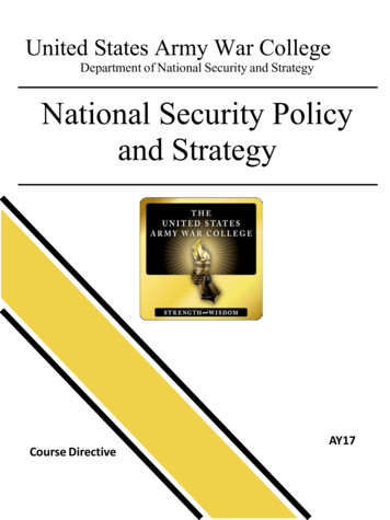
5. INDUCTORA coil or loop, which has the property to oppose any change in alternating current is called aninductor.LINDUCTANCEIt is the property of a circuit or a component that opposes a change in current. Represented by Land the unit is Henry (H).Inductance of a coil depends on1. The number of turns; more the number of turns, greater is the inductance of the coil.2. PermeabilityConductor Contains InductanceFlux between coils3. Cross section larger the cross section of the core, higher is the inductance,4. Spacing of the turns: the smaller the spacing between turns of the coil, the higher is theinductance.INDUCTANCE IS OF TWO TYPES1. SELF INDUCTACNE2. MUTUAL INDUCATANCESELF-INDUCTANCEThe ability of a conductor to induce voltage in itself when the current changes. When current flowsth
Study Manual for Amateur Station Operator’s Licence Examination National Institute of Amateur Radio, Raj Bhavan Road, Hyderabad -500082, India . Amateur Station Operators’ License (G eneral) Ex amination Part I - Written Test Section A: Radio Theory and Practice