Transcription
Embedded Control SystemsLecture: MW 130-3PM 1311 EECSLabs: 4342 EECSJeff Cookjeffcook@eecs.umich.eduOffice: 4238 EECSZhaori Cong (Thursday 9:30)zcong@umich.eduJeff Roder (Tuesday, Thursday 1:30)roderjef@umich.eduJohn Schmotzer (Monday 3:30,Wednesday 10:00)jwschmo@umich.edu
Embedded Control Systems Background:– University of Michigan and Ford MotorCompany, 2004– Control theorists and computer scientists: whydo we have to hire one of each to developembedded controls?– Teach a little computer engineering to controltheorists, and a little signal processing andcontrol to computer engineers– Also taught at ETH (2008)
Important Points No textbook– www.eecs.umich.edu/courses/eecs461– Lecture notes, microprocessor reference material, laboratoryexercises, homework problems and lots of other importantinformation will be posted– Syllabus lists some useful (but not required) books on embeddedsystems programming– I’ll mention during lecture what you should be reading Homework will be Matlab, Simulink, Stateflow– Problem sets will be posted on the website– Typically have one week per problem set. Homework is due at thebeginning of class. Late homework will not be accepted. TheHomework Policy is posted on the course website, and included inthe syllabus.
Important Points Laboratory exercises– 8 laboratory exercises plus a project using theFreescale MPC5553 microprocessor Most labs are “1-day” (1 lab per week) First lab will be two weeks beginning Monday, 12January – BUT MLK day on 19 January meansMonday section has only one scheduled lab Lab instructors will have “open hours” on Friday, 16January and/or Friday 23 January for Mondaystudents. Check with your lab instructor for times– 6 lab stations with 2 students (“self organize”)
Important Points Special lecture on embedded systemprogramming– Important information for lab #1– When to do this lecture? Monday? but lab starts at 3:30 Special lecture on Friday?– Same time and place, if I can get the room
Important Points Laboratory exercises have 3 parts:– Pre-lab: questions that require you to read themicroprocessor reference material and gatherthe information required to complete the labexercise– In-lab: the experiment– Post-lab: questions that should reinforce whatyou learned in the lab exercise– Read the “lab policy” in the syllabus
Other Useful Information Grading:– Homework: 25%– Laboratory Assignments: 25%– Quizzes (tentatively scheduled for February 18th andApril 1st): 30%– Project: 20% Office Hours: 10:00 - Noon, Monday andWednesday, but feel free to stop by or email me toset up an appointment Email alias: eecs461@eecs.umich.edu– See syllabus for instructions
Outline Embedded systems and embedded control systems Laboratory description– Freescale MPC5553 microcontroller– Software development environment– Haptic interface Lecture Topics Laboratory Exercises
What is an Embedded System? Technology containing a microprocessor as acomponent– cell phone– PDA– digital camera Constraints not found in desktop applications––––costpowermemoryinterface Embedded processor is often the performance andcost limiting component!
What is an Embedded Control System? Technology containing a microprocessor as acomponent used for control:––––––AutomobileAircraft and UAVActive control of civil structuresManufacturing toolsHousehold appliancesMany others
Characteristics of Embedded ControlSystems Interface with external environment– sensors and actuators “Real time” critical– performance and safety– embedded software must execute in synchronywith physical system Distributed control– networks of embedded microprocessors
Skills Required for Embedded Controls Algorithms (control, signal processing,communications) Computer software (real time, multitasking) Computer hardware (interfacing, memoryconstraints) Digital electronics Sensors and actuators Mechanical design Multi-disciplinary!
Industry Trends Increasing complexity of embedded control systems andsoftware– Actuators, sensors, processors, networks– Typical small car contains 70 microprocessors Model based embedded control software e generationRapid prototypingHardware in the loop (HIL) testing “Separation between control design and controllerimplementation is not sustainable in embedded market”** Industry Needs for Embedded Control Education, Tutorial Session 2005 ACCJ. Freudenberg (UM), B. Krogh (CMU), J. Cook (Ford), K. Butts (Toyota), J. Ward (Eaton)
An Embedded Design Team May consist of:– Applications engineers Model the systems to be controlled, design controlalgorithms– Hardware specialists Low-lever drivers and other hardware specific design– Software engineers Write C code from specifications given to them byapplications engineers Applications engineers, hardware engineersand software engineers have to communicate!
Languages Some assembly language– device drivers, highly optimized code Most coding done in C– interest in C and Java, but too much overhead forhighly constrained applications Automatic code generation– automatically generate C code from a Matlab/Simulinkmodel used to design and test control algorithm– currently useful for rapid prototyping on non-productionprocessor– also used for high end applications (NASA)
MPC5553/5554 Examples: AutomotiveApplications Powertrain– Fuel and ignition control– Aftertreatment control for diesels– Valve control, turbocharger control, transmission controlincluding CVT– Control of hybrid-electric powertrains Safety– ABS, traction control, electronic stability control, rollovercontrol Lots of I/O: sensors & actuators– Real time critical: performance & safety– Harsh environment (EMI, noise, vibration, temperature)
Automotive Distributed Systems:Mobile Networking High-speed CAN Low-speed CAN Local Interconnect Network(LIN) Media Oriented SystemsTransport (MOST) Bluetooth Intelligent TransportationSystem Data Bus (IDB 1394) FlexRay, Time-triggeredCAN
Application of the MPC555 (predecessor ofthe MPC5553) SeaScan transoceanic pilotless aircraft ScanEagle Intelligence, surveillance and reconnaissance support;USS Oscar Austin (DDG 79) Guided Missle Destroyer The Insitu Group: www.insitu.com
Laboratory Overview MPC5553 Microcontroller (Freescale)– Originally automotive control, now used in manyapplications Development Environment– Debugger (P&E Micro)– Codewarrior C compiler (Freescale) Haptic Interface– Force feedback system for human/computer interaction Rapid Prototyping Tools– Matlab/Simulink/Stateflow, Real Time Workshop (TheMathworks)– RAppID Toolbox (Freescale) Real Time Operating System– OSEKturbo RTOS (Freescale)
Freescale MPC5553 Microcontroller 32 bit PPC core– floating point– 132 MHz– -40 to 125 HC temperature range Programmable Time Processing Unit (eTPU)– Additional, special purpose processor handles I/O that would otherwiserequire CPU interrupt service (or separate chip)– Quadrature decoding– Pulse Width Modulation Control Area Networking (CAN) modules 2nd member of the MPC55xx family– real time control requiring computationally complex algorithms– MPC5554 replaces MPC555 for powertrain control– MPC5553 has on-chip Ethernet for manufacturing applications
MPC5553 EVB Evaluation board (Freescale)-32 bit PPC core-floating point-128 MHz Interface board (UofM)– buffering– dipswitches– LEDs– sliding potentiometer
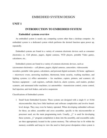
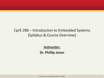
Nexus Compliant Debugger (P&E Micro)
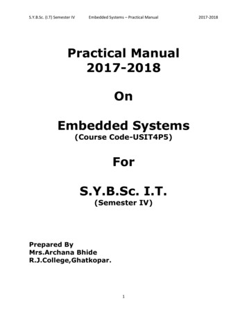
Haptic Interface Enables human/computer interaction throughsense of touch–––––force feedback joystickvirtual reality simulators (flight, driving)training (surgery*, assembly)teleoperation (manufacturing, surgery**)X-by-wire cars Human visual sensor: 30 Hz Human haptic sensor: 500Hz-1kH* D. Sordid and S. K. Moore, “The Virtual Surgeon”, IEEE Spectrum, July 2000.** J. Rosen and B. Hannaford, “Doc at a Distance”, IEEE Spectrum, October 2006.
Force Feedback
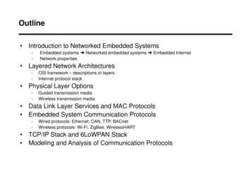
Haptic Wheel Prof. Brent Gillespie, Mech Eng Dept, UofM––––DC motorPWM amplifier w/ current controlleroptical encoder128/18 gear ratio
Haptic Wheel(New and Improved for 2009)
Virtual Environments§Virtual wall§Virtual spring-mass
Steer-by-wire AutomobilesR. Iserman, R. Schwarz, S. Stolzl, “Fault Tolerant Steer-by-Wire Systems”IEEE Control Systems Magazine, October 2002.
Lab Station
Lectures (I) QuantizationSamplingLinear filteringQuadrature decodingDC motorsPulse Width Modulation (PWM) amplifiersMotor control: current (torque) vs. speedMPC5553 architecture. Peripherals: eTPUs, eMIOS, eDMA, Haptic interfaces.– virtual wall– virtual spring/mass/damper Simulink/Stateflow modeling of hybrid dynamical systems Numerical integration.
Lectures (II) Networking:– Control Area Network (CAN) protocol.– Distributed control Interrupt routines: timing and shared data Software architecture–––– Round robinRound robin with interruptsReal time operating systems (RTOS)MultitaskingShared data: semaphores, priority inheritance, priority ceilingReal time computation. Rate monotonic scheduling.Rapid prototyping. Autocode generation.Model based embedded control software developmentPID control design
Laboratory Exercises Each teaches– a peripheral on the MPC5553– a signals and systems concept Each uses concepts (and code!) from the previous labs Lab 1: Familiarization and digital I/OLab 2: Quadrature decoding using the eTPULab 3: Queued A-D conversionLab 4: Pulse Width Modulation and virtual worlds without timeLab 5: Interrupt timing and frequency analysis of PWM signalsLab 6: Virtual worlds with time.Lab 7: Controller Area Network (CAN)Lab 8: Rapid Prototyping
Lab 1: Familiarization and Digital I/O Use General Purpose Input/Output (GPIO) on MPC5553 Read two 4-bit numbers set by dipswitches, add thevalues and display the results on LEDS
Lab 2: Fast Quadrature Decoding Position measurement using an optical encoder Optical encoder attached to motor generates two 90H outof phase square waves: QD function on MPC5553 eTPU:decodes quadrature signal into counter CPU must read counter before overflowIssue: How fast can wheel turn before counter overflows?
Lab 4: Virtual Wall Software loop– read position from encoder– compute force F 0 or F kx– set PWM duty cycle Rotary motion– degrees encoder count– torque PWM duty cycle– 1 degree into wall 400 N-mmtorque Wall chatter– large k required to make stiffwall– limit cycle due to* sampling* computation delay* quantization* synchronization
Lab 6: Virtual Spring-Mass System Virtual spring-mass system: reaction force F k(w-z) Measure z, must obtain w by numerical integration Use interrupt timer to generate a time step&& mk w wθzθwkwJwhaptic wheelθ&&w Jk θ z virtual wheelkmzkJwθz
Lab 6: Design Specifications Choose k and Jw so that– virtual wheel oscillates at 1Hz– maximum torque in response to 45 degree step in wheelposition is 800Nmm Verify design in Simulink before testing on hardware
Lab 7: Controller Area Networking (CAN) Networking protocol used in time-critical applications– automotive– manufacturing Messages have unique identifiers: priorities Allows computation of worst case response time Lab exercises:– a wall that is chatter free when wall implemented locally canchatter due to delay when implemented remotely– connect each wheel to its virtual neighbors with virtualsprings to create a virtual chain of 6 labstations.– estimate network utilization.
Rapid Prototyping (I) Lab 8 involves automatic code generation fromSimulink models:––––––Derive a mathematical model of system to be controlledDevelop a Simulink/Stateflow model of the system.Design and test a control algorithm using this model.Use Real Time Workshop (RTW) to generate C-code.Eliminates coding errors.Speeds product development: generated code can be testedin many design cycles– Hand coding still required for production
Model Based Embedded Control Software Development
Rapid Prototyping (II) Need Simulink blocks:– device drivers– processor and peripheral initialization Issues:– efficiency of generated code– structure of code Multitasking– with RTOS, task states– without RTOS, nested interrupts
OSEKturbo RTOS (Freescale) OSEK/VDX compliantScalableTask schedulerPriority ceiling protocolEliminates– deadlock– priority inversion
RAppID Toolbox (Freescale) Processor and peripheral initialization blocks Device driver blocks Enables multitasking with OSEKturbo RTOSor nested interruptsRAppID MPC5554 Target SetupSystem Clock : 128 MHzTarget : MPC5554Compiler : metrowerksTarget Type : IntRAMOperating System : simpletargetRAppID-EC
Lab 8: Two virtual wheels Two subsystems:– High priority fast subsystem– Low priority slow subsystem Model the multi-rate system in Simulink Demonstrate real-time operating system(RTOS)
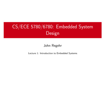
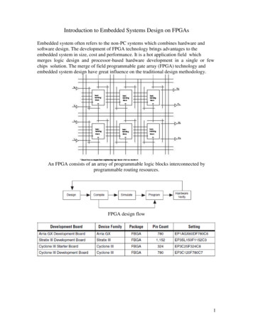
Project (at UM):Adaptive CruiseControl Distance Control– Follows target at timedheadway in ACC mode by useof throttle and brakes Speed Control– Automatically returns to cruiseset speed when target ive CruiseControl Algorithm
Project: Adaptive Cruise Control Driving simulator Bicycle model of vehicle 6 vehicles interactingover CAN network ACC algorithm: 3 states– manual (sliding pot)– constant speed– constant distance Takes 3 weeks, all donewith Simulink, Stateflow, andautocode generation
Embedded Control Systems Jeff Cook jeffcook@eecs.umich.edu Lecture: MW 130-3PM 1311 EECS Labs